TABLE OF CONTENTS
USER WARNINGS...................................................................................................................1
RECOMMENDATIONS FOR CORRECT INSTALLATION OF WEIGHING INSTRUMENTS.1
MAIN CHARACTERISTICS OF THE INSTRUMENTS............................................................2
BUFFER BATTERY....................................................................................................................2
TECHNICAL SPECIFICATIONS..............................................................................................3
W100, W200...............................................................................................................................3
WDESK-LIGHT...........................................................................................................................3
WDESK-L/R, WINOX-L/R/2L, WTAB-L/R .................................................................................3
ELECTRICAL CONNECTIONS................................................................................................4
BASIC INFORMATION...............................................................................................................4
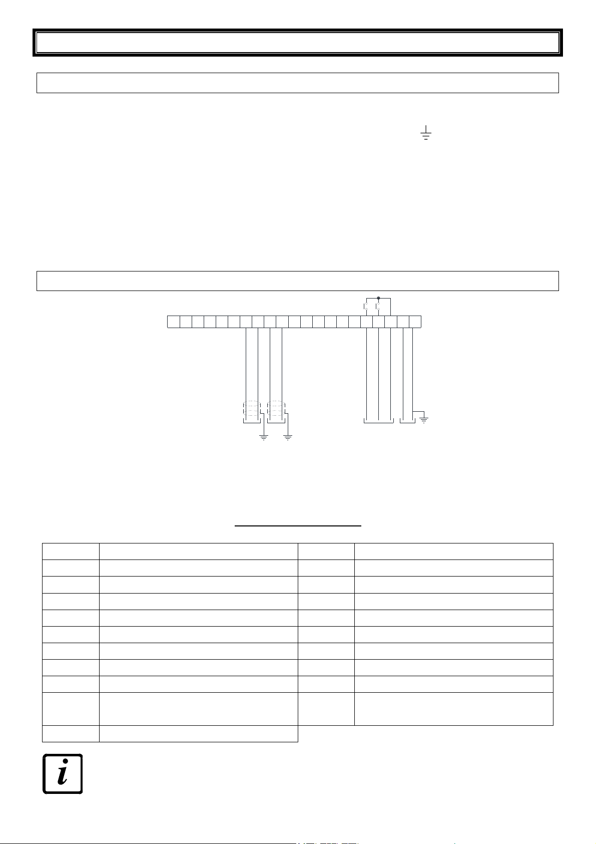
WDESK-LIGHT...........................................................................................................................4
TERMINALS LEGEND........................................................................................................................4
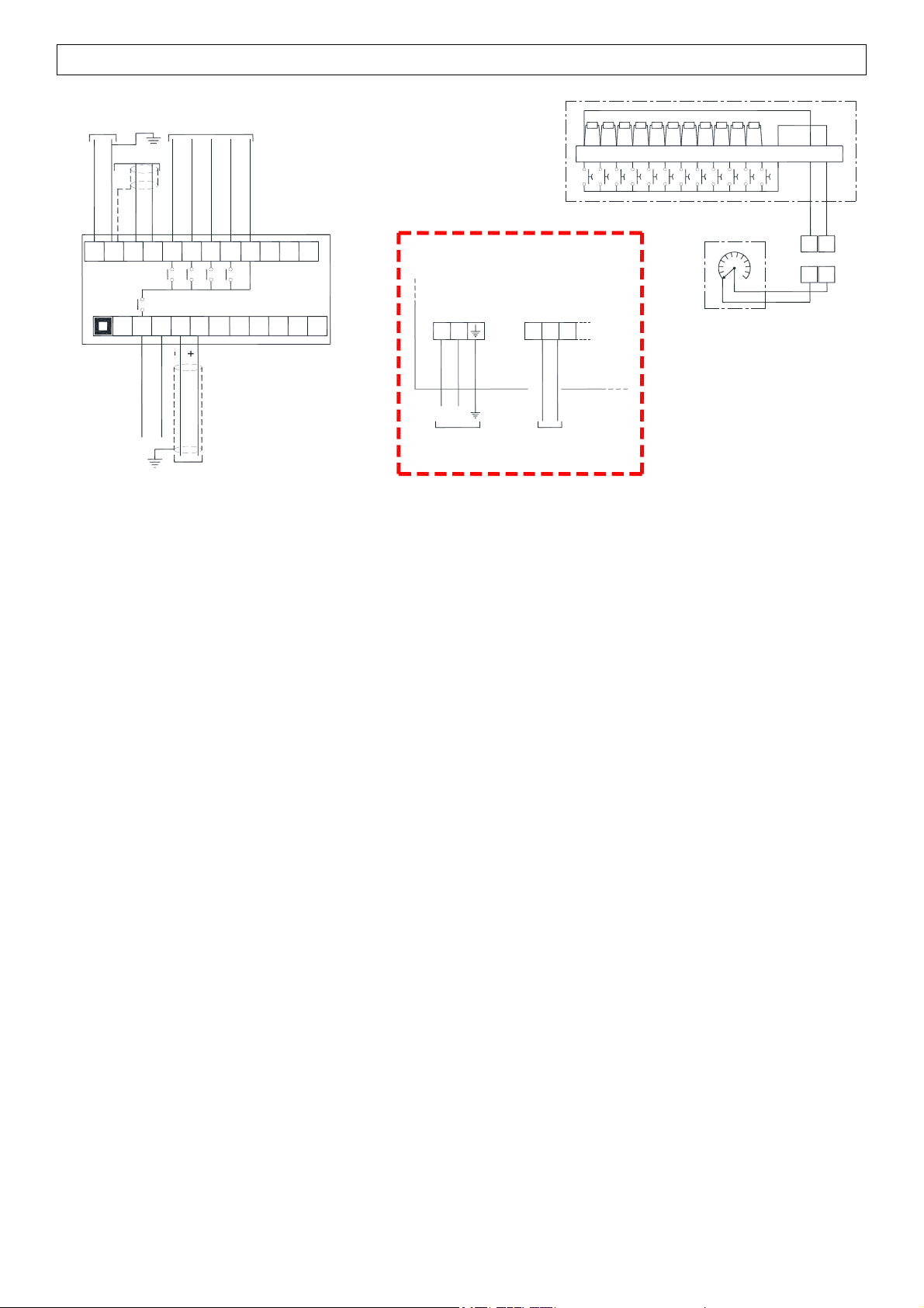
W100 – W200.............................................................................................................................5
CHANGING VOLTAGE 115 VAC/230 VAC (W200)...........................................................................6
TERMINALS LEGEND........................................................................................................................6
WDESK-L/R – WINOX-L/R/2L – WTAB-L/R .............................................................................7
CHANGING VOLTAGE 115 VAC/230 VAC (WDESK-L/R) ...............................................................7
INSTRUMENTS BACK TYPES...........................................................................................................8
KEY TO P, Q, X TYPE CONNECTORS..............................................................................................8
KEY TO D TYPE CONNECTORS.......................................................................................................9
RS485 SERIAL COMMUNICATION ........................................................................................10
RS232 SERIAL COMMUNICATION ........................................................................................10
LED, SYMBOLS AND KEY FUNCTIONS..............................................................................11
MENU MAP ............................................................................................................................12
SETPOINT................................................................................................................................12
SYSTEM PARAMETERS.........................................................................................................12
PROGRAMMING OF SYSTEM PARAMETERS....................................................................13
SERIAL COMMUNICATION SETTINGS .................................................................................13
SETTING THE NUMBER OF DECIMALS................................................................................13
SETTING UNIT OF MEASURE................................................................................................13
SELECTION OF THE WEIGHT TYPE TO DISPLAY...............................................................14
OUTPUTS AND INPUTS CONFIGURATION ..........................................................................14
TEST.........................................................................................................................................14
DATE AND TIME SETTING.....................................................................................................14
SETPOINT PROGRAMMING.................................................................................................15
ALARMS.................................................................................................................................15
RECEIVING PROTOCOL.......................................................................................................16
RESERVED FOR THE INSTALLER......................................................................................17
MENU LOCKING......................................................................................................................17
MENU UNLOCKING.................................................................................................................17