Lawn Genie L60204 Operating instructions
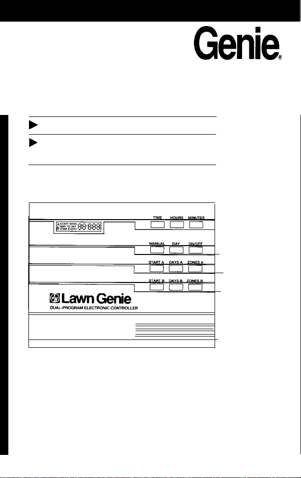
Lawn
Genie@
Dual-Program Electronic Controller
Installation and Operation Guide
b
For Models
L60204,
L60206P,
L60208P
b
Please read instructions completely before
attempting to install or operate
controller.

This manual explains
how to install your
Lawn Genie sprinkler
controller and program
it for the watering
schedule that's right
for you. The following
sections are arranged
to match the most
efficient installation
sequence. Refer to
them in the order pre-
sented for best results.
Introductionn
...............................................................
3
Features
......................................................................
5
Installation
Installing the controller..
................................................
6
Connecting the valves..
.................................................
7
Connecting the transformer and battery
......................
8
Programming
Setting the current time................................................
9
Selecting theright Program
........................................
10
Setting thestart times................................................
11
Setting the run time and Program for each Zone.........
12
Setting the day schedules
...........................................
14
Typical program for lawn &garden
.............................
16
Additional information
Installing
a
pump-startrelay
.......................................
17
Special
functions........................................................
19
Trouble-shooting
.........................................................
20
Wateringconsiderations............................................
21
Warranty.....................................................................
22
Zone Legend
...............................................................
24
Your Lawn Genie sprinkler
controller is the heart of
your automated watering
system. It lets you supply
different parts of your lawn
and garden with precisely
the water they require,
exactly when they require
it. All without any effort on
your part once you’ve pro-
grammed your system.
This Lawn Genie controller
gives you four waysto con-
trol how you distribute
water
to various parts of your yard.
Here’s how they work:
Zone
control
Lawns, shrubs, flower beds
and other foliage all need
different amounts of water.
You can tailor the water
delivered to different parts
of your yard by assigning
a different run time to one
or more sprinkler valves.
Each valve and the sprinklers
it controls are called a Zone.
The
L60204
lets you divide
your yard into as many as four
Zones; the
L60206P
allows
up to six; and the
L60208P
permits a maximum of 8 Zones.
Programming options
Certain parts of your yard may
need water every day. Other
parts may need water only
twice a week. Dual program-
ming lets you divide your
Zones into two different
groups, and assign each
group a different interval
between days or different
specific days of the week to
water. For example, Program
A may water Zones
1,3,4
and 5 every third day, and
Program B may water Zones
2 and 6 only on Monday
and Friday. For details, see
“Selecting the right
Program” on page 10.
Start times
This controller lets you
specify up to six different
times to start watering
the Zones it controls. Start
times may be shared
between Program A and
Program B in any combi-
nation, for example, two
start times in Program A;
4 in Program
B.
and so on.
Watering run time
To deliver the correct
amount of water to each
Zone, you can program
each Zone to shut off after
a specified period of
time-
from 1 to 99 minutes.
Here’s how the controller connects to your system
Plug-in
Controller unit
Automatic
Automatic
transformer anti-siphon
in-line valve
;$kler
valve
(some installations)
DUAL-PROGRAM ELECTRONIC CONTROLLER
I
I I I
II
q
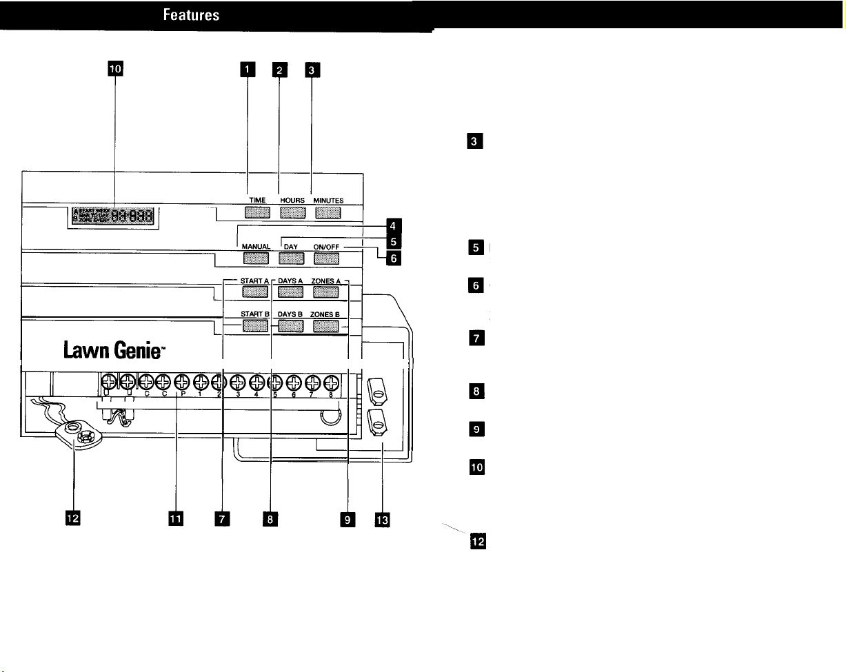
(1) Time key
For
setting time of day.
q
(2) Hours key
For setting current hour, start-time hour, and advancing run time in
1-minute increments.
m
Minutes key
For setting current minute, start-time minutes, and advancing run time in
l-minute increments.
q
(4) Manual key
For
temporarily
interrupting a watering cycle in progress, or manually start
ing a watering cycle at other than the programmed time.
q
em
(5) Day key
For setting current day.
On/Off key (Rain Switch)
For preventing watering during wet weather or winter, and de-activating
Zones using the Zones and Days keys.
Start keys
For setting up to six start times per day shared between Program A and
B
in any combination.
Days keys
For setting watering days for each Program.
Zones keys
For programming run times for each Zone.
Display
Shows current time of day, Zone being watered and watering run time.
(11) Terminal screws
For connecting valve wires to controller.
Battery connector
For installing 9-volt battery for backup power in case of power failure.
q
(13) Plug-in transformer
For converting
120-volt
household current into safe, low-voltage power.
(250-volt
source on 50 Hz units.)
Select the location
_
A. Choose an indoor location near a standard
120-volt
dual electrical outlet.
(250-volt
outlet for 50 Hz
international units.)
!
CAUTION: Don’t place the controller where
temperatures may exceed
130”
Fahrenheit
(55” Centigrade), on a circuit controlled by a
switch, or on the same circuit as a high power
user (refrigerator air conditioner garage door
opener. etc.). Ma/functions may result.
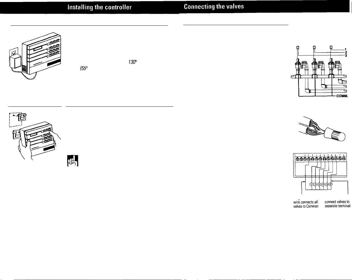
A. Run valve wiring underground wherever possible.
For line runs less than 800 feet long, use 18-gauge,
plastic jacketed thermostat control wire; over 800 feet,
use 14-gaugewire. Your dealer can provide this wire in
2.3.4.5.6.7and 8-wire color-coded strands.
8. Connect a single common wire to one of the wires
from each valve.
C. Solder or join all splices with wire nuts; then seal
with vinyl or waterproof cement to assure a water-
resistant connection.
Mount the controller
A. Install the controller mounting bracket at eye level
using two screws.
B. Position controller over mounting bracket engaging
tabs into recessed slats in back of controller housing.
To lock in place, pull down on controller until tabs reach
built-in stops,
IMPORTANT
The power transformer is protected
by an electronic circuit breaker Do not connect a
combination of valves requiring an inrush current
of more than
1
amp at 24 VAC. (One valve only for
regular models. Two valves for P-Series models.)
Connect the valve wires to controller
NOTE: To install controller on a plaster or masonry A. Run all valve wires up through hole in bottom of
wall, use plastic or lead shields to secure screws. controller.
Wire the
valves
B. Connect the wire from valve number
1
to the terminal
screw marked 1 on the controller; the wire from valve
number 2, to the terminal 2, and so on. This allows your
controller to selectively water the Zone controlled by a
valve.
Wires to
individual
controller terminals
Common
wire
to single controller
terminal
One wire from each valve connects to
a single common wire running to
controller.
Single common
lndividual wires
C. Connect the common wire to the terminal marked C.
~$e,“$$$~~
r$$$r~$~r$
D. If using a water pump or master valve, refer to (C)terminal
page 17 for installation details (P-Series controllers only).
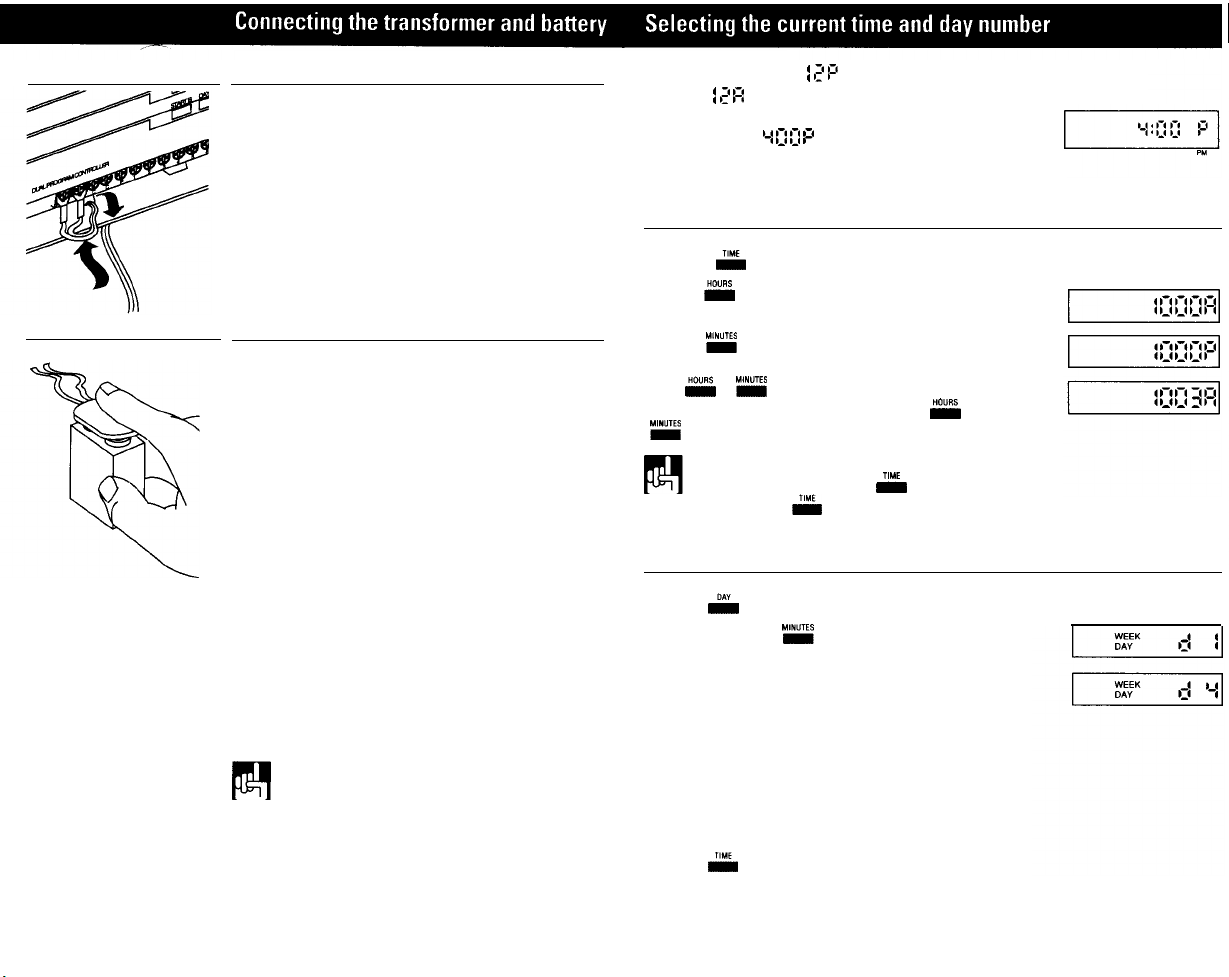
Connect the transformer
A. Run the power cable from the transformer up through
the smaller of the two openings in the bottom of the
controller,
B. Connect one lead to each terminal screw marked 24V
Make sure terminals at the end of the cable do not touch.
C. Plug in the transformer.
ACAUTION: Use with supplied transformer ONLY!
Connect the battery
A battery back-up system is built into your Lawn Genie
controller to maintain your programmed watering
schedule in memory in case of temporary power failure.
A. Connect a 9-volt alkaline battery (not supplied) to
the battery connector in the wiring compartment
of the controller case.
B. Place the battery in the wiring compartment by
pushing the connector end, in and under the transformer
power cable terminals.
C. Replace the wiring compartment cover,
D. Replace the battery once a year. More often if frequent
power failures occur.
ACAUTION: Do not allow the battery connector to
touch the transformer power cable, or the terminal
wiring to the right. D0 not connect or disconnect
valve wires while any Zones are in operation,
NOTE. Check local codes to ensure that wiring
and installation meet all requirements.
In the controllers display,
i
,z
P
represents 12PM, or
noon, and
]
,z
R
represents 12 AM, or midnight. When
the power is first turned on, the controller always
displays a time of
‘-I
0
0
P(4:00 PM). Setting the current
time is easy.
Set the current time:
A. Press
&
B. Press
E
and hold key down until display shows
current hour and A (AM) or P(PM).
C. Press
w
and hold key down until display
shows current minute. To advance time quickly, hold
down
E
or
ME
until desired time approaches.
To advance time slowly, digit by digit, press
E
or
MG
once for each hour or minute of advance.
NOTE: You must begin setting time within
30
seconds after pressing
&
Otherwise,
you must press
&
once again.
Set the current day number
A. Press
D*y
6. Repeatedly press
MG
until the current day
number is displayed. Days are represented by the
following numbers.
Sunday = 1
Monday = 2
Tuesday = 3
Wednesday = 4
Thursday = 5
Friday = 6
Saturday = 7
C. Press
flM(
to return to the clock mode
This manual suits for next models
2
Table of contents
Other Lawn Genie Lawn And Garden Equipment manuals


Popular Lawn And Garden Equipment manuals by other brands

Sunforce
Sunforce SOLAR user manual

GARDEN OF EDEN
GARDEN OF EDEN 55627 user manual

Goizper Group
Goizper Group MATABI POLMINOR instruction manual

Rain Bird
Rain Bird 11000 Series Operation & maintenance manual

Cub Cadet
Cub Cadet BB 230 brochure

EXTOL PREMIUM
EXTOL PREMIUM 8891590 Translation of the original user manual


Vertex
Vertex 1/3 HP Maintenance instructions

GHE
GHE AeroFlo 80 manual

Land Pride
Land Pride Post Hole Diggers HD25 Operator's manual

Yazoo/Kees
Yazoo/Kees Z9 Commercial Collection System Z9A Operator's & parts manual

Premier designs
Premier designs WindGarden 26829 Assembly instructions

Snapper
Snapper 1691351 installation instructions