Lawn Genie LD6 - CO M/R IRRIGATION 6 Zone Controller... User manual

/
I,
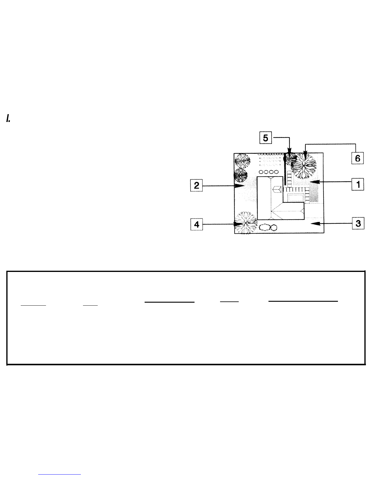
Introduction: What is a Watering Cycle?
Each watering cycle opens and closes all the valves assigned to a
program, in sequence, starting with the lowest valve number. For
example, in the sample watering plan shown, program
A
has two
start times which initiate two watering cycles. All four valves in the
program water in sequence, two times each day, once at
7:OOam
and once at
5:OOpm.
The LD4 is designed to operate up to four
valves. The LD6 is designed to operate up to six valves. Each
can be set to start two watering cycles per program. Each of the
two programs are completely independent of each other giving
you the freedom to include any combination of valves in each
program and the ability to select different watering days and start
times for each program. After programming, write your watering
plan in pencil on the back of the programming reference card,
located in the controller pull-out pocket. For the days you have
selected in programs
A
and
B.
each programmed start time turns
on each selected valve in sequence, from the lowest valve
number to the highest valve number.
Sample Watering Plan
Proqram Days
Water Start Times Valves Valve Run Time Duration
A
Su, M
O
, Tu, We, Th,
Fri,
Sa
(1)
7:OOam
1,2,3,4
10 minutes
(1,3,4)
15 minutes (2)
(2)
5:OOpm
Same as above
B
Odd Days (1)
5:OOam
4,5,6
30 minutes each (4,5,6)

II. Guided Programming
(Optional)
In guided programming, the controller
display
prompts you to
enter data for items by flashing the appropriate A. It automatically
prompts you to supply information about the current time and
date, program start time(s), valve run time(s) and watering days
for program A and program B. After all items are entered
,
an
“OK”
will be flashed five times to verify programming is complete.
If you have not entered the required data during the guided
programming session, the controller will flash the message “-
-
-
-
“,
and prompt you for the missing data. The purpose of guided
programming is to allow you to enter a program without this
manual.
To begin, set dial to GUlDED PROGRAM. This will lead you
through five easy steps. Use the + and
-
buttons to increase or
decrease times. Use the
4
button to enter your selection and to
advance to the next step. After setting the time and date,
program A (or B) A will flash. You will be prompted to complete
program A. If required, you may continue with program B by
pressing the A/B button. After the final programming step, the
controller will flash
“OK”. You
will then be prompted to set-up the
other program,
B
(or
A),
if desired. After all desired programming
is done, set dial to RUN position to begin automatic operation.
Hint: Plug in 9 volt alkaline battery to
allow
programming at
your kitchen table.
install
controller after programming by
battery.
Guided
Programming Steps
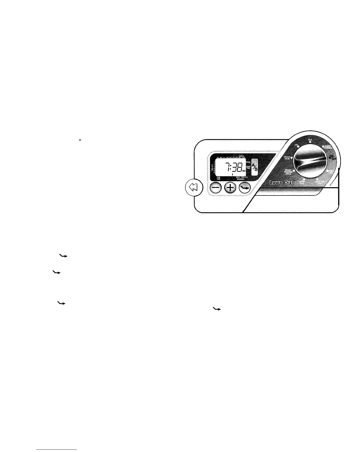
1. T/ME/DATE -Enter the year, the month, the date and the
time. This will set the controller’s internal timing. Use + and -
buttons to increase or decrease values and the
4
button to
go to the next step.
2.
PROGRAM A or
B
-
Select either program
A
or
B.
Press the
3.
4.
5.
A/B
button to select. Press
4
button to go to the next step.
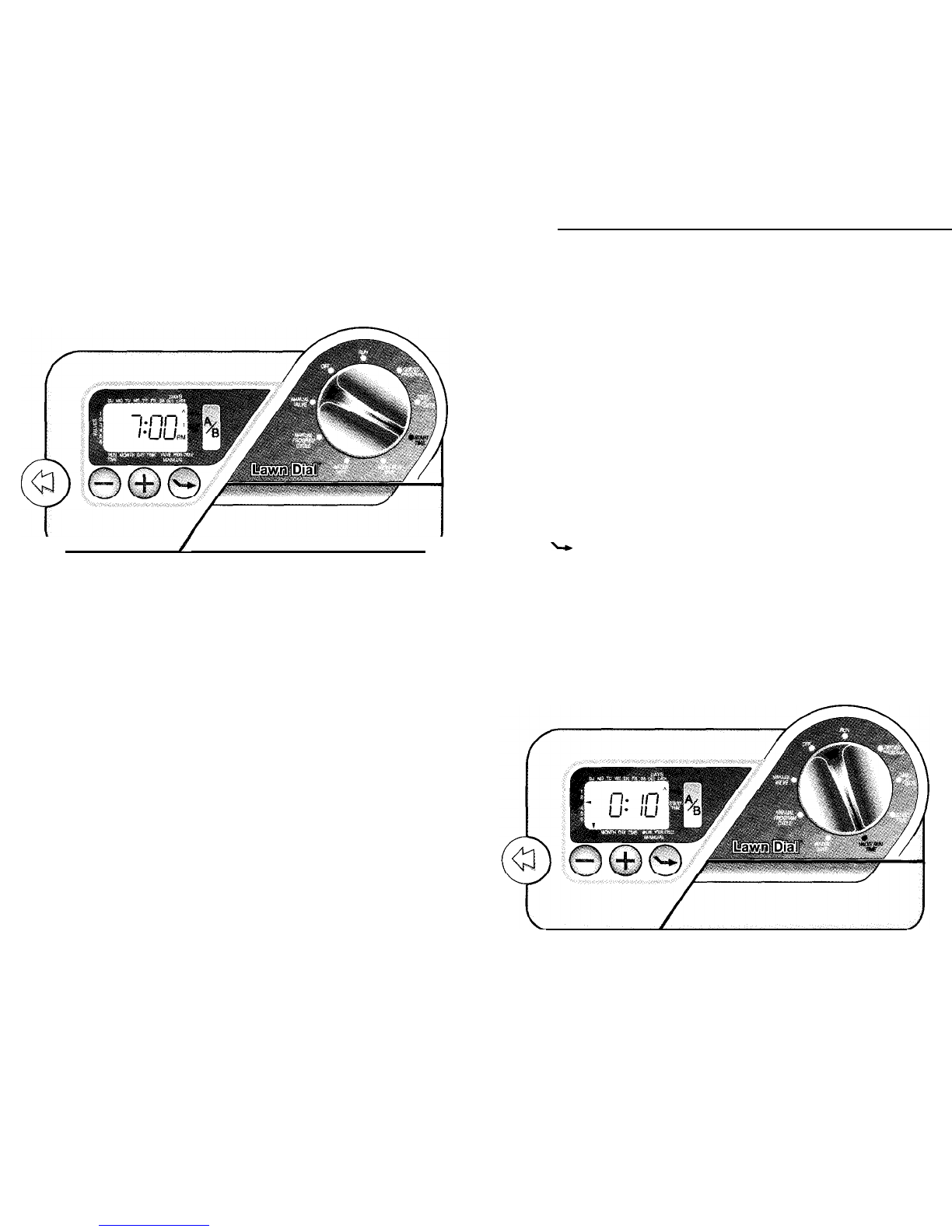
START T/ME
-
Enter the program watering start time(s). Each
program can have up to two start times. (Two start times allow
watering twice a day.)
‘VALVE
RUN T/ME
-
Enter the length of time that each valve is
to run. You may select a few minutes for a light sprinkling, or
you may set the valve to
remain
open for up to four hours for
applications such as drip. (The valve is off when the run time is
set to zero minutes and the display shows “OFF”). Press + or
-
buttons to increase or decrease the minutes of run time per
valve. Press
4
button to go to the next valve or to the next step.
WATER DAYS -Enter which days should be watering days.
You may select particular days of the week, all odd days or all
even days. Press the + button to turn days on and the
-
button
to turn days off. Press the
4
button to go to the next day or
to the next step.
Return the dial to the Run position after you have completed
programming.
Note: Programs A and B III Each program is simply a set of
instructions that direct which valve to run for how long and
on which days. If you need four start times or extra long
watering times, you will need to use both programs.
However, in most cases one program will be sufficient.
III.
Dial Programming
Use dial programming to set all elements of your program without
the help of guided programming or to simply review and update
existing program information.
Setting Time and Date
1.
Set the dial to the TIME/DATE position.
2.
Year:
Use the + and
-
buttons to change the year.
3.
Month:
Press the
4
button to set the month. Use the + and
-
buttons to change the month.
4.
Day:
Press the
4
button to set the day of the month. Use the
+ and
-
buttons to change the day of the month. The day of
the week, (e.g. Sunday, Tuesday, etc.), is automatically
indicated by the A pointing to the correct day.
5. Time: Press the
4
button to set the time. The hour, minute
and AM or PM will flash. Use the + and -buttons to change
the hour and minute time shown on the display. (Continuous
pressure on the button longer than 3 seconds causes rapid
change.)
Selecting
Program
Stati
Times
Each program has two start times available. You may use the
second start time to water more than once per day.
1.
Set the dial to the
START TIME
position.
2.
Select program
A
or
B
by pressing the
A/B
button.
3. Use the + and -buttons to change the start time. (Continuous
pressure on the button, longer than 3 seconds, causes rapid
change.)
4. Press the
4
button to select the next start time.
/
Canceling a
Program
Start
Time
1. With the dial set to the START TIME position, use the + and
-
buttons to set the start time to
Off,
(which is between the times
of
1159pm..
.OFF..
.12:00am..
.12:01
am..
.).
To accomplish
this, you can go forward or backward in time.
2. If a program has both start times turned off, then that program
is Off. (All other program details are retained). Because there
are no start times, there will be no watering with that program.
This is a convenient way to stop one program without turning
the dial to the
OFF
position. You may need the other program
to water.
Setting
Valve Run
Times
Follow the steps below to program how long each valve will
water.
1.
Set the dial to the
VALVE RUN T/ME
position.
2. Select program A or B.
3. The display will flash the valve number A, the run time for that
4. valve, and will show the program letter selected (A or
B).
Use the + and
-
buttons to change the time shown on the
display. (Continuous pressure on the button, longer than 3
seconds, causes rapid change.)
5. Press
4
to advance to the next valve.
6.
Repeat steps 4 and 5 for each valve.
7. You may set valve run times from zero minutes to four hours.

Selecting Days to Water
1.
Set the dial to WATER DAYS.
2. Select program
A
or
B.
3.
The controller displays currently programmed day information.
This dial position provides three different water day options:
specific days of the week, odd days, or even days.
Selecting Odd or Even Days
Selecting Specific Days of the Week
1. Press the + button to turn on a particular day of the week to
water. Press the
-
button to turn watering off for that day.
2. Press the
4
button to advance to the next day of the week/
3.
Repeat steps 1 and 2 until all desired days have been selected.
The selected days will show at the top of the display to
indicate their status as ON.
1. Press the
4
button for Odd Days and once again for Even
Days. The A will flash under your choice.
2. Press the + button to select or the
-
button to cancel either
Odd Days
or
Even Days.
The previously selected days of the
week will revert to active if Odd Days or Even Days is
canceled.
Note: The 31st of any month and the 29th of February of a
leap year, are always treated as Off days in Odd Days
watering.
Run
After programming, set dial to RUN to enable automatic
execution of all selected programs and start times.
Note: During the operation you will notice a 10 second delay
between the time a valve shuts off and the next valve opens.
This is to prevent water pressure damage to your system.

Off
Use this dial position to turn off watering, such as when it is
raining or you don’t want watering. As long as the dial is in the
OFF position, watering programs will not be activated
automatically. The OFF position is also used to terminate all
running program A or Bwatering cycles, whether manual or
automatic.
1.
2.
Set the dial to the OFF position. Valves currently watering will
be turned off after dial is in OFF position for at least two
seconds. All active programs are discontinued and watering
is stopped.
To return controller to normal automatic operation, simply
return dial to RUN position.
Warning:
In warm weather you may experience landscape
damage if the dial is left unintentionally in the OFF position
for extended periods of time. Always return the dial to RUN
position if automatic operation is desired.
IV.
Manual Programming
Manual Program Cycle
Use this feature to manually start a program. For example, this
can be used to start a program an extra time on a particularly hot
day.
1.
Set the dial to the
MANUAL PROGRAM CYCLE
position.
2. Select program
A
or
B.
3.
Press the + button to select manual program cycle.
4. Press the
4
button until the desired starting valve is
displayed. That valve and all subsequent valves in the selected
program will water in sequence.
5. Return the dial to the RUN position to begin the manual
watering cycle. Display shows
MANUAL PROGRAM CYCLE A,
program
A
or
B,
valve number A, and counts down the remaining
run time for each active valve.

6.
Turn the dial to the OFF position for longer than 2 seconds to
discontinue the manual program cycle. (Always return dial to
RUN position to enable automatic operation.)
Manual Valve
Use this feature to start one or more valves watering sequentially
for a selected period of time.
To Select Valves for Timed Manual
1.
Set the dial to the
MANUAL VALVE
position.
2.
3.
The valve 1 A will flash. You may use the + and
-
buttons to
select the amount of time for valve 1 to water or skip to the
next desired valve by pressing the
4
button.
Select the valves to water and their watering duration by
repeating step 2 for the remaining valves.
4. Set the dial to the RUN position. Valves will water sequentially
for the set time with the operating valve’s A blinking during its
manual watering operation.
5. Turn the dial to OFF position for longer than 2 seconds to
discontinue the manual valve program. (Always return dial to
RUN position to enable automatic operation).
Note: You may advance through a running cycle by pressing
the
4
key to skip any undesired valve(s).
V.
Installation
Selecting an Installation Site
Install the controller with the display at eye level. The controller
must be mounted at least 15 feet away from your pump
start
relay
and pump. Do not plug the controller into any
power
circuit
serving a refrigerator, a pump or an air
conditioner.
WARNING: This controller is designed for indoor installation
only. Installing this controller outdoors will void the warranty
and may result in an electric shock hazard.
Mounting the Con troller
1. Determine mounting height and center position. From this
location mark a point 2
l/4”
(57 mm) to the right and 2
l/4”
(57mm) to the left. Drive a screw into the wall at each point
leaving approximately
l/8”
(3mm) of the screw exposed. Hang
the controller on the two exposed screw heads.
2.
To secure the controller, remove door and drive the third screw
through the bottom mounting hole in the controller.
Do not plug transformer into power source until the
controller is mounted and ALL valves have been
connected.
3. If you have not already done so, connect a 9-volt alkaline
battery clip. DO NOT use a rechargeable battery. The display
will illuminate under normal conditions. If any unexpected
display characters show, simply disconnect and reconnect the
battery. After a few minutes the display will go blank under
battery power. Turn dial to illuminate display. The battery is
designed as a memory retention feature only. Valves will only
operate with power supplied by the transformer.
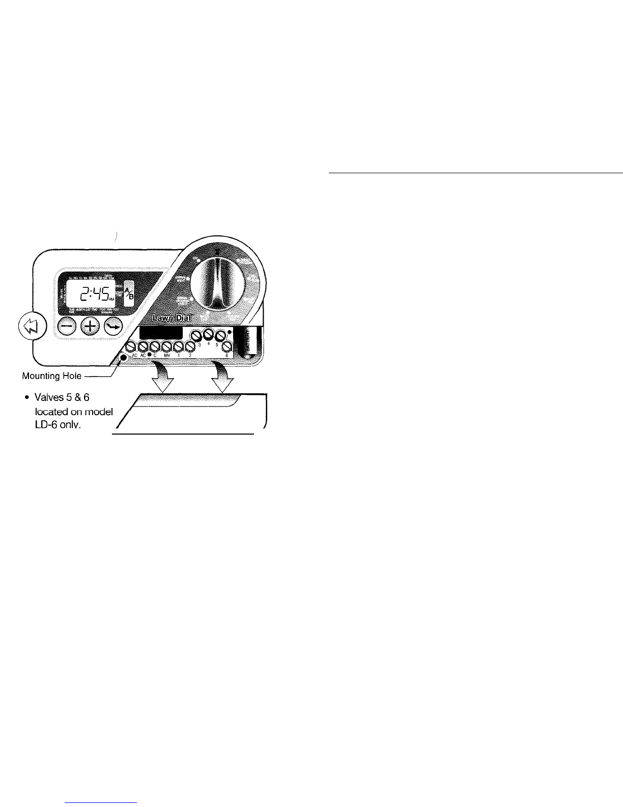
Connecting the Valves
&
Transformer
DO NOT try to connect the controller directly to an outlet. This
WILL destroy the controller and may result in electric shock or fire
hazard. Please use only single strand multi-colored irrigation wire
for your installation.
1.
Connect the transformer wires to the two screws marked AC.
Do not plug in
transformer
until after all valves have
been connected.
2.
Connect valve
#l
wire to screw marked 1 and the “valve
common” wire to main common wire which feeds back to the
controller. Typically, you will have all of your valves grouped
together. From this valve group you will send your multi-
colored wire bundle back to the controller. Then, the single
common wire is connected to the common terminal screw
marked C. (See diagram.) In some cases, you may have more
than one common wire. One from the front yard and one from
the back yard. All commons get connected to the terminal
screw marked C. If a number of commons are required, you
may need to use a “wire nut” to combine these commons
together with a lead wire. The single lead wire is then
connected to the common terminal screw marked C. Back
screw out until head is
1/8"
above plastic partition. Bend bare
copper wire in clockwise hook (only expose
l/2”
of bare
copper from end of wire to reduce short circuiting of two
adjacent wires). Slip wire hook under screw head and tighten
screw until wire is secure.
3.
Repeat step 2 for all valves.

WARNING: Make sure
the
power transformer is unplugged
while making connections to any station or master
valve/pump output terminal.
WARNING:
A maximum load of
6VA,
(which is equivalent to one Lawn Genie,
Hardie, or Richdel valve), may be connected to each numbered
valve terminal. A maximum load of 12 VA may operate
simultaneously (i.e. one valve at a time in addition to the master
valve).
The relay coil must be rated for 24 VAC at 250 MA maximum. The
relay contacts will be connected to the pump start terminals and
must be rated for use with your particular pump. (See diagram). In
addition, a high pressure relief mechanism is recommended. See
your pump dealer for more information.
l
Valves 5
&
6
located on model
LD-6 only.
PUMP START RELAY
TO PUMP
or PUMP
STARTER _
c
CONTACTS MUSS
ACCOMODATE
PUMP’S
ELECTRICAL RATING
PUMP
POWER
Connecting a Pump Start Relay
The controller must be mounted at least 15 feet away from
both the pump start relay and the pump.
When a pump is to be
operated by the controller, a pump start relay must be used. The
relay coil should be connected to the master valve output
terminal marked MV and the common terminal C at the controller.
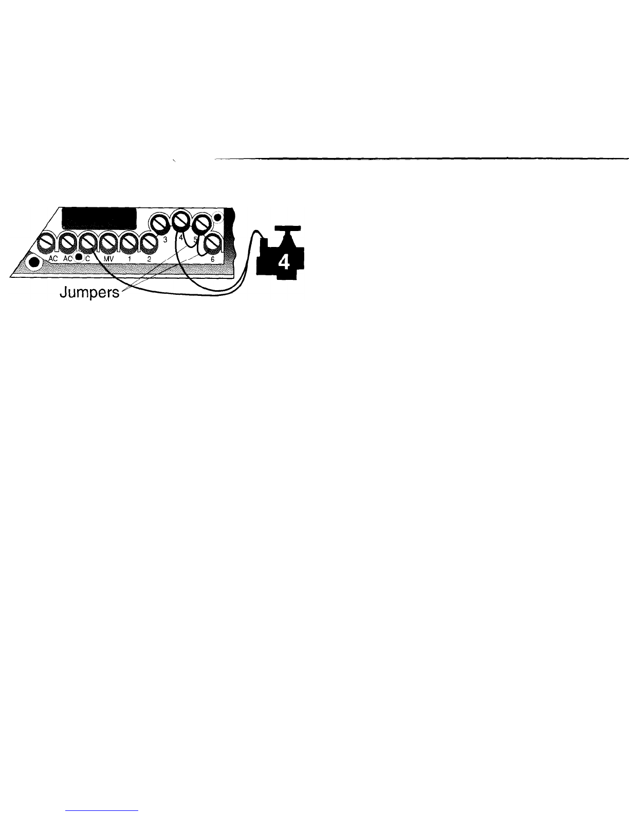
WARNING:
If
a pump start is installed you must use a
jumper wire from each unused terminal screw to a numbered
terminal screw in use. This is critical to avoid damaging your
pump, (i.e. running it dry, which may burn out the pump
motor.) Neglecting to jumper all unused terminal screws may
seriously damage your pump during default program
execution.
DO NOT connect the master valve output terminal directly to the
pump start terminals. This WILL damage the controller.
Master Valve/ Pump Start
The Master Valve/Pump Start will operate whenever any valve is
on. This allows a pump to draw water from a well or other source,
or opens the master valve whenever watering occurs. The
practice of using a pump is common in some areas and rare in
others. (If you do not have a pump start or master valve installed,
you will not notice this feature,)
Power Failures
Due to the possibility of power failures, the controller has a
factory set safety default program which assures watering even if
your programs have been lost due to a discharged or missing
back-up battery. The default program is set to run all valves for
ten minutes each, every day of the week. The default is factory
set in Program
A.
Note: You may change Program A to suit your needs without
affecting the default. You may change all the programs to
suit your specific needs, without affecting the factory default
values. There is no factory default for program
B.
Note: This controller is only intended for use in an automatic
irrigation sys tern.
Fuse (1amp)
A replacement fuse is provided with this controller. Further
replacements can be obtained from the dealer who supplied this
controller.
WARRANTY
Limited Warranty: Hardie Irrigation warrants to its customers that
this product will be free from defects in materials and
workmanship for a period of three years from the date of
purchase. We will replace, free of charge, the part, or parts found
to be defective under normal use and service for a period of three
years after purchase, proof of purchase required.
We reserve the right to inspect the defective part prior to
replacement. Hardie Irrigation will not be responsible for
consequential or incidental cost or damages caused by product
failure.
For additional assistance, call our Customer Service Hot-line at
l-
800-231-5117.

FCC
This equipment has been tested and found to comply with the
limits for a class B digital device, pursuant to Part 15 of the FCC
Rules. These limits are designed to provide reasonable protection
against harmful interference in a residential installation. This
equipment generates, uses and can radiate radio frequency
energy and, if not installed and used in accordance with the
instructions, may cause harmful interference to radio
communications. However, there is no guarantee that
interference will not occur in a particular installation. If this
equipment does cause harmful interference to radio or television
reception, which can be determined by turning the equipment off
and on, the user is encouraged to try to correct the interference
by one or more of the following measures:
0
Reorient or relocate the receiving antenna.
l Increase the separation between the equipment and
receiver.
l
Connect the equipment into an outlet on a circuit different
from that to which the receiver is connected.
0Consult the dealer or an experienced
radio/TV
technician
for help.
This equipment has been verified to comply with the limits for a
class B computing device, pursuant to FCC rules. In order to
maintain compliance with FCC regulations, shielded cables must
be used with this equipment. Operation with non-approved
equipment or unshielded cable is likely to result in interference to
radio and TV reception. This user is cautioned that changes and
modifications made to the equipment without the approval of
manufacturer could void the user’s authority to operate this
equipment.
27631 La Paz Road
Laguna Niguel, CA 92677
For Technical Support Call: l-800-231 -5117
Part Number
LD-4/6
MAN Rev.B OLawn
Genie
12196
This manual suits for next models
2
Table of contents
Other Lawn Genie Lawn And Garden Equipment manuals


Popular Lawn And Garden Equipment manuals by other brands

Simplicity
Simplicity 1694919 Illustrated parts list

Simplicity
Simplicity 3536 Illustrated parts list

LITTLE BEAVER
LITTLE BEAVER Kwik-Trench KT200B user manual

Pastore & Lombardi
Pastore & Lombardi 12-V 0834 26156A operating instructions

Oypla GARDEN
Oypla GARDEN 3884 user manual

EarthQuake
EarthQuake 9800B Operating & parts manual


Corradi
Corradi Bioclimatics Maestro user manual

Wilo
Wilo Wilo-Sevio AIR Installation and operating instructions

Easy-Garden
Easy-Garden P581 Assembly instructions

Grizzly
Grizzly BRV 400 S Translation of the original instructions for use

GOTEL
GOTEL AGD-04-U quick start guide

Alamo
Alamo John Deere 6615 Assemble, instruction manual