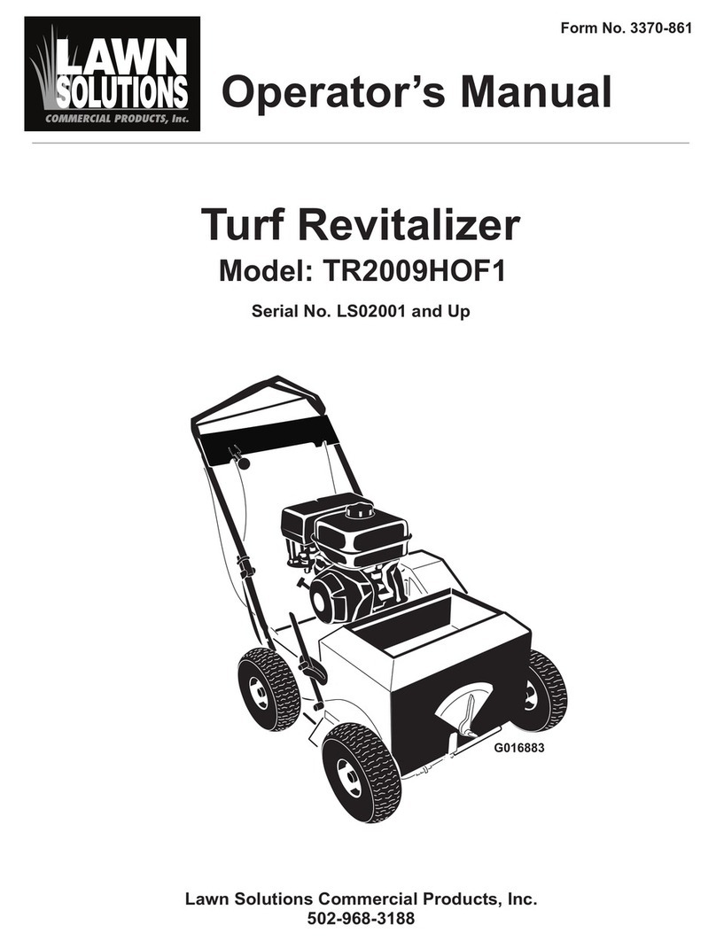
Lawn Solutions Turf Revitalizer User manual

Turf Revitalizer
6 - 14hp
Owner’s Manual

- 2 -
CONTENTS Page#
Safety……………………..……….…..3
Unpacking and Initial setup…..….…4-5
Controls..……………………………6-8
Operation……………………….….9-10
For Best results………….………..10-11
Servicing your Turf Revitalizer….12-16
Storage………………………………16
Troubleshooting……………………..17
Warranty……………………………..18
Parts Breakdown………...…………..19

- 3 -
Safety
Do not start and/or run engine indoors. Engine produces carbon
monoxide and can cause severe bodily harm, including death.
Read entire owner’s manual before operation.
Do not refuel engine until engine has cooled off.
The exhaust becomes very hot during operation. Never touch the muffler
as this will cause severe burns.
Never operate unit without all safety guards in place. This includes, but is
not limited to the belt, and blade cutter reel covers.
Make sure that you and any bystanders are wearing personnel protection
equipment. Including eye and hearing protection along with long pants.
Do not wear loose fitting clothes or jewelry as this may become caught in
rotating parts. (Children should never operate machinery.)
Never bypass kill switches.
Do not leave unit while engine is running, or while parts are still in
motion.
Check for buried cables, wires, and irrigation pipes before seeding,
dethatching or power raking.
Remove all debris from area to be seeded, as debris may become flying
projectiles.
Use extreme caution on slopes. Wear shoes with an aggressive pattern to
reduce chances of slipping and/or falling.
Avoid running over manhole covers, concrete, asphalt, rocks, etc…while
seeding. This may cause damage to the unit. If abnormal vibration occurs
discontinue use of machine until service can be performed.
Always disconnect sparkplug before servicing.

- 4 -
Unpacking and Initial Setup
Unpacking
Step1. Cut away crate.
oUse a reciprocating saw to cut away wooden crate.
Step2. Fold Handles up. (Note: On the 13-14HP units this task
takes two people.)
oUnits are shipped with the handle folded in the down
position. Handle bolts must be removed to correctly
position the handle (see figure1). Secure the handle with
all four bolts.
Step3. Remove unit from pallet.
oPull the “transmission engagement T-handle” out, this
puts the unit into neutral/freewheel (see figure 1b).
oPull the unit off of the pallet. This may be difficult as the
transmission has not been “broken in”.
Figure 1 Figure 1b
Remove Bolt and
move to middle
hole.
Pull Out to
manually
move unit

- 5 -
Initial Setup
Step1. Top the engine off with oil.
oUnits are shipped with some oil. Engine should be topped
off with the correct oil viscosity. See engine manual for
the correct oil viscosity.
Step2. Adjust the transmission cable. (Note: On the 13-14HP
units the blade engagement cable will need to be installed at
handle; See page 13 for proper adjustment procedures.)
oStart the engine. If the transmission is “creeping” in the
“Park" position (see figure 2) adjust the cable. Moving
the cable down will stop forward creep. Moving the cable
up will prevent reverse creep.
Figure 2
NOTE:
The transmission and cutter belt will stretch during the first
5 hours of use. They must be adjusted to prevent the belts
from slipping, causing premature belt wear. See page 13-14
for the correct procedure on adjusting the belts.
Adjusting nuts for
transmission.

- 6 -
Controls
Note: Seed Flow –the seed flow is turned on/off with the seed flow control.
The unit is designed so seed flow slows or almost stops completely when the
front wheels are off the ground while making turns. There is no need to turn
the seed flow on & off for each turn. Once the front wheels start turning, the
seed flow will instandly go back to the calibrated seed rate.
Seed Flow
ON / OFF
Cutter Blades
ON / OFF
Pistol Grip
Transmission
Control

- 7 -
Pistol Grip Control- the unit is operated
(forward and backward) using a pistol grip
control, like those found on a commercial walk
behind mower. Disengage the lever, with your
thumb, from the “park” position and release
slowly to move forward (Note: 9-14 HP units
have two forward cruising speeds). To stop,
squeeze the control half way. To go backward,
squeeze the control fully. See figure 4.
Figure 4.
Transmission engagement T-handle- This must
be inserted into the frame for the transmission to
operate. If you want to manually push the unit,
pull the t-handle out of the frame and down to
lock into neutral/freewheel. See figure 5.
Figure 5.
Depth Control Lever –The “Depth Control
Lever” is used to raise and lower the blades.
This allows a maximum range of blade heights.
Pull on the spring plunger knob to release the
lever and then lower and raise the blades to the
desired position. See figure 6. Do not force
handle from side to side, it is made to move
forward and backwards only.
Figure 6.

- 8 -
Seed Meter Gauge –The “Seed Meter
Gauge” is used to adjust the seed flow to a set
flow rate. It is calibrated so that you receive
the correct amount of seed at any cruising
speed. (i.e. –the seed flow is proportional to
the ground speed)See figure 7.
Figure 7.
Operator Kill Switch (Lanyard type) –The
“Operator Kill Switch” is to be used at all
times when the engine is running. Place the
lanyard around your wrist or connect securely
to your clothing. If the operator should lose
control of the machine, the lanyard will be
released from the kill switch stopping the unit.
See figure 8.
Figure 8.
Operator Kill Switch (Operator handle kill
switch type) –The handle needs to be held
down when starting the engine and must
continue to be held during operation. If the
operator should lose control of the machine,
release your hand from this switch and the
engine will stop running. See figure 9.
Figure 9.

- 9 -
Operation
Before each day of use.
oCheck engine oil level and air filter.
oCheck for loose or damaged parts.
oClean dirt and debris from seed gate by turning seed flow
setting (seed meter gauge) to #10, then turn the seed flow
on. Then go to the front of the unit and move the seed gate
back and forth 4-5 times to remove any dirt and debris.
NOTE: The seed gate is designed to clean itself when it
is allowed to move through the full range of motion.
See figure 3 on next page.
Operation
1. Set the seed flow to the recommended seed rate.
2. Move the depth control lever to the recommended height.
3. Attach the lanyard to operator. If not equipped with a lanyard, hold
down the operator’s presence handle.
4. Make sure that the “pistol grip control”is in the parked position.
5. Turn on/off switch on engine to on.
6. Turn fuel on.
7. If engine is cold turn choke on. If engine is warm leave choke off.
8. Start the engine and turn off the choke.
9. Move the “transmission engagement T handle” into the frame if it is
pulled out.
10.Tilt back on the unit and turn the cutter reel on. Slowly lower the
unit to the ground.
11.Turn seed flow on.
12.Move “pistol grip control”into desired direction of travel.

- 10 -
13.After use be sure to set the engine switch to off, shut off fuel, and
return the blades to the highest position.
Figure 3.
For Best Results
The Turf Revitalizer is a 3 in 1 machine that will power seed, dethatch,
and power rake.
Power Seeding –When over seeding, set the blades to cut slits in the soil
¼” – ½” deep. For basic over seeding, only 1 pass is required. If there are
a few bare areas due to fungus or dog urine, seed the entire property with
one pass, on the bad areas, go forward then backward and forward again to

- 11 -
add extra seed. This method will save time and seed while giving a nicer
finished product.
Dethacthing –Because of the Turf Revitalizer’s aggressive blade design,
you can use the same machine for dethaching. Simply turn off the seed
flow and do a single or double pass as desired. It is recommended to
dethatch even a newly seeded lawn the following spring or fall to allow
the grass to thicken properly which reduces the chance of fungus.
Power Raking / Renovation –The Turf Revitalizer is the most compact
yet powerful power rake on the market. For breaking new ground,
leveling, or renovating a lawn, drop the blades down to 1”-1 ½” deep. Use
the hydrostatic drive to do the work for you. Go forward and backward
with the machine to till the ground in very uneven areas, or simply make a
double pass in two directions to break up and level the ground in moderate
areas. Hard, dry ground works the best. The unit is much more
aggressive when breaking up hard dry ground while going backward
because the blades are reverses tilling the soil. Multiple passes may be
needed if the ground is too soft and engine bogs down. In which case
make a couple of shallow passes then increase the cutting depth.
Note: The Turf Revitalizer will seed at the same rate going forward and
backwards.
Note: If there is excessive thatch, it may be necessary to remove the thatch
prior to seeding. This will prevent the new grass from suffocating under
the thatch.
Note: With the Turf Revitalizer, it is very easy to put more grass seed
down then is recommended because of the thinking that “more is better”.
Grass that is too thick is very susceptible to fungus during summer
months. Seed at the recommended seed rate, most seed rates can be
located on the seed bag, or can be obtained from your supplier.
Note: Unit performs best when ground is dry.

- 12 -
Servicing your Turf Revitalizer
The Turf Revitalizer is designed to be relatively maintenance free. For long
life and to reduce down time some routine service should be performed.
Note: Always disconnect the sparkplug before servicing.
After each day of use:
Units should be tipped forward. Let the seed hopper rest on a piece of
wood i.e. 2x4. Note: For the 13-14HP units it takes two people to tip
unit forward.
Check the underside for excessive build up of dirt. Scrape excessive
build up off with a PLASTIC putty knife. PRESSURE WASHING
WILL CAUSE EXCESSIVE RUST! This will shorten the life of the
bearing.
Check for rope, plastic netting, wire…etc. that is wrapped around the
cutting shaft and remove the foreign material.
Look at blades and check for damage.
Hold shaft and move in and out to check for excessive movement. If
there is excessive movement have unit serviced.
Check belts for wear and proper tension.
Flip unit back over and check the air filter and engine oil level.
After Five hours of usage:
Adjust the belt tension! If this step is skipped premature belt failure
will occur. If belt failure occurs the cutter belt can be replaced by a
standard off the shelf belt found at most auto parts stores when
needed. However we recommend using the appropriate replacement
belt from your local dealer.
NOTE: The drive belt to the transmission is a specially designed belt
that must come from your dealer. OFF THE SHELF BELTS WILL
NOT WORK!

- 13 -
oProcedure for adjusting “cutter reel”belt tension.
1. Remove the belt cover.
2. Turn on Cutter Reel.
3. With the engine off and the blades in the up position, press
forward on the belt tensioner. The belt should be tight and
the “cutter cable” should be slightly loose.
4. Turn the blades to the off position, and the tensioner should
deflect the belt ass shown causing the belt to release from
the drive pulley allowing the blades to free wheel.
5. Note: It is normal for the cutter reel to spin when
disengaged for the first 5 hrs of operation or until belt is
broken-in (stretches).
6. Replace belt cover.
Loosen Adjusting
nuts here.

- 14 -
oProcedure for adjusting transmission belt tension.
1. Remove the belt cover.
2. Loosen all four nuts shown in figure 11.
3. Slide idler bracket away from engine to increase tension. If
movement cannot be obtained insert four c-washers in
between the idler bracket and the frame, see figure 12.
4. Retighten all four nuts and replace belt cover.
Figure 11.
Figure 12.
Slide “c-washer
between plate
and frame on all
four bolts.

- 15 -
Change engine oil at the recommend intervals. Refer to your engine
manual for these intervals and correct viscosities.
There is no maintenance to the hydrostatic drive system. It is
designed to be completely sealed to prevent contamination.
The blades are designed to be “unbreakable”. When replacing worn
blades, it is also recommended to change the cutter bearings while
they are off the unit as preventative maintenance.
oProcedure on replacing blades and bearings.
1. Units should be tipped forward. Let the seed hopper rest
on a piece of wood i.e. 2x4. Note: For the 13-14HP units
it takes two people to tip unit forward.
2. Remove the belt cover and cutter belt.
3. Lower the blades to allow easier access to bolts.
4. Remove cutter reel.
5. Note: If removing blades only it is not necessary to
remove pulley or bearing from the drive pulley side.
Loosen the jam nut enough to remove tension from the
external snap on the opposite end of the shaft.
6. Replace blades and spacers. Note: Be sure to stagger
blades as they are put on.
7. Note: if doing annual service, it is recommended to
replace the cutter reel bearings at this time.
8. Note: Also make sure that thread lock is used on all set
screws and the jamb nut.Also use anti-seize on all
bearings and pulleys (any metal to metal surface) as
you slide them on the shaft. See figure 13.
9. Reinstall in unit and check for smooth operation.
10. Adjust cutter belt if needed.

- 16 -
Figure 13. “TL”-Thread Lock.
Seed gate cable adjustment.
1. Set seed flow to off position.
2. Check for any gaps in between the seed gate and frame.
3. Make any needed adjustments to the seed gate cable if needed. Do
not adjust the cable where there is excessive tension placed on the
cable due to pulling the seed gate past the limit of travel.
Storage and Troubleshooting
Storage
Follow the “after each use” section on page 12.
Drip a couple of drops of oil down each cable to prevent rust from
forming on the cables.
Drain fuel from engine and carburetor bowl, or add a fuel stabilizer.
TL
TL, Set
Screws
Antiseize
shaft!

- 17 -
Troubleshooting
Problem
Possible Cause
Correction
Engine will not
start.
Out of gas.
Low Oil.
Kill switch.
Fill gas.
Top off oil.
Hold down OP handle
or attach lanyard.
Engine shutting off
on hills or when
turning.
Engine is low on oil.
Oil switch is detecting
low oil.
Top engine off with
oil.
Remove orange wire
from the front off the
engine if hill is
excessive (> 30 deg.)
Engine is stalling.
Blades are set to deep
in the ground or ground
is too wet.
Set blades to a higher
setting or wait for
ground to dry.
Transmission won’t
engage.
Transmission T-handle
not inserted into frame.
Insert T-handle, see
page 7.
Unit lacks power
going up hills.
Transmission belt is
slipping due to belt
stretch.
Follow adjusting
procedure on page 14.
Seed hopper gate
will not open.
Dirt is building up
between the seed gate
and frame.
See page 9, for
cleaning procedure.
Excessive vibration
Broken blade.
Worn bearing.
Replace all blades.
Replace both bearings.

- 18 -
Warranty
Limited Warranty for Turf Revitalizer (6hp and 14hp models)
The product carries a 2-year limited warranty from the date of purchase for the original
purchaser. Lawn Solutions will replace for the original purchaser free of charge any
part or parts found to be defective in material or workmanship. Lawn Solutions may
require the defective parts to be returned for further examination. Due to the ease of
maintenance on the product, this is a parts only warranty.
This is a limited warranty and does not cover damage from abuse to include failure to
transport the product correctly. The warrant does not cover standard service items like
belts, blades, bushings and bearings.
On 3rd party items like an engine and transmission, Lawn Solutions may provide
replacement parts, but it will be up to the OEM to refund any warranty work or part
costs.
Lawn Solutions will overnight parts if requested and at the cost of the requester,
otherwise Lawn Solutions will pay standard shipping charges except for 3rd party items
(engine and transmission).

- 19 -
Control Panel ASM

- 20 -
Front Parts View
Side Parts View
Table of contents
Other Lawn Solutions Lawn And Garden Equipment manuals