Lawn Solutions TR2009HOF1 User manual

Turf Revitalizer
Model: TR2009HOF1
Lawn Solutions Commercial Products, Inc.
502-968-3188
Serial No. LS02001 and Up
Form No. 3370-861
Operator’s Manual
G016883

WARNING
CALIFORNIA
Proposition65Warning
Theengineexhaustfromthisproduct
containschemicalsknowntotheStateof
Californiatocausecancer,birthdefects,
orotherreproductiveharm.
ThissparkignitionsystemcomplieswithCanadian
ICES-002.
Important:Thisengineisnotequippedwitha
sparkarrestermufer.ItisaviolationofCalifornia
PublicResourceCodeSection4442touseoroperate
theengineonanyforest-covered,brush-covered,or
grass-coveredland.Otherstatesorfederalareas
mayhavesimilarlaws.
Introduction
Thismachineseeds,dethatches,andpowerrakesturf
bothforrevitalizingexistingturfandforspreading
seed.Itisintendedforsmalltomediumsizedlawn
applicationsinresidentialandcommercialproperties.
Readthisinformationcarefullytolearnhowtooperate
andmaintainyourproductproperlyandtoavoidinjury
andproductdamage.Youareresponsibleforoperating
theproductproperlyandsafely.
YoumaycontactLawnSolutionsdirectlyat
http://lawnsolutionscp.comforproductandaccessory
information,helpndingadealer,ortoregisteryour
product.
Wheneveryouneedservice,genuineLawnSolutions
parts,oradditionalinformation,contactanAuthorized
ServiceDealerorLawnSolutionsCustomerService
andhavethemodelandserialnumbersofyourproduct
ready.Figure1illustratesthelocationofthemodeland
serialnumbersontheproduct.Writethenumbersin
thespaceprovided.
G016889
1
Figure1
1.Locationofthemodelandserialnumbers
ModelNo.
SerialNo.
Thismanualidentiespotentialhazardsandhassafety
messagesidentiedbythesafetyalertsymbol(Figure2),
whichsignalsahazardthatmaycauseseriousinjury
ordeathifyoudonotfollowtherecommended
precautions.
Figure2
1.Safetyalertsymbol
Thismanualuses2otherwordstohighlightinformation.
Importantcallsattentiontospecialmechanical
informationandNoteemphasizesgeneralinformation
worthyofspecialattention.
©2011—LawnSolutionsCP
5406ShepherdsvilleRd.
Louisville,KY402282
Contactusathttp://lawnsolutionscp.com.
PrintedintheUSA.
AllRightsReserved

Contents
Introduction.................................................................2
Safety...........................................................................3
SafeOperatingPractices.......................................3
SlopeIndicator.....................................................5
SafetyandInstructionalDecals.............................6
Setup...........................................................................7
UnfoldingtheHandle...........................................7
CheckingtheEngineOilLevel..............................7
TestingtheTransmissionAdjustment...................7
ProductOverview........................................................7
Controls...............................................................7
Specications.....................................................10
Operation...................................................................10
CheckingtheEngineOilLevel............................10
CleaningDebrisfromtheMachine......................11
AddingFuel.......................................................11
StartingandStoppingtheEngine........................12
OperatingtheMachine.......................................12
OperatingTips...................................................12
Maintenance...............................................................14
RecommendedMaintenanceSchedule(s)................14
PremaintenanceProcedures....................................14
DisengagingtheHydrostaticDrive.....................14
DisconnectingtheSparkPlugWire.....................15
EngineMaintenance...............................................15
ServicingtheAirCleaner....................................15
ServicingtheEngineOil.....................................16
CleaningtheSedimentCup.................................16
ServicingtheSparkPlug.....................................16
DriveSystemMaintenance.....................................17
CheckingtheTirePressure.................................17
AdjustingtheTransmission.................................17
BeltMaintenance....................................................18
AdjustingtheTransmissionDriveBelt
Tension..........................................................18
SeederMaintenance................................................19
AdjustingtheSeedGateClosedPosition.............19
ReplacingWornCuttingBlades...........................20
Storage.......................................................................21
Safety
Improperuseormaintenancebytheoperator
orownercanresultininjury.Toreducethe
potentialforinjury,complywiththesesafety
instructionsandalwayspayattentiontothesafety
alertsymbol,whichmeans
Caution
,
W ar ning
,or
Danger
—personalsafetyinstruction.Failureto
complywiththeinstructionmayresultinpersonal
injuryordeath.
SafeOperatingPractices
ThefollowinginstructionsarebasedontheANSI
B71.4—2004andB71.8—2004standard.
Training
•ReadtheOperator’sManualandothertraining
material.Iftheoperator(s)ormechanic(s)cannot
readEnglishitistheowner’sresponsibilitytoexplain
thismaterialtothem.
•Becomefamiliarwiththesafeoperationofthe
equipment,operatorcontrols,andsafetysigns.
•Alloperatorsandmechanicsshouldbetrained.The
ownerisresponsiblefortrainingtheusers.
•Neverletchildrenoruntrainedpeopleoperateor
servicetheequipment.Localregulationsmayrestrict
theageoftheoperator.
•Theowner/usercanpreventandisresponsiblefor
accidentsorinjuriesoccurringtohimselforherself,
otherpeopleorproperty.
Preparation
•Evaluatetheterraintodeterminewhataccessories
andattachmentsareneededtoproperlyand
safelyperformthejob.Onlyuseaccessoriesand
attachmentsapprovedbythemanufacturer.
•Wearappropriateclothingincludingsafetyglasses
andhearingprotection.Longhair,looseclothing,or
jewelrymaygettangledinmovingparts.
•Inspecttheareawheretheequipmentistobeused
andremoveallobjectssuchasrocks,toys,andwire
whichcanbecontactedbythemachine.
•Useextracarewhenhandlinggasolineandother
fuels.Theyareammableandvaporsareexplosive.
–Useonlyanapprovedcontainer.
–Neverremovethegascaporaddfuelwiththe
enginerunning.
–Allowtheenginetocoolbeforerefueling.
–Donotsmoke.
3

–Neverrefuelordrainthemachineindoors.
•Checkthattheoperatorpresencecontrols,safety
switches,andshieldsareattachedandfunctioning
properly.Donotoperateunlesstheyarefunctioning
properly.
Operation
•Neverrunanengineinanenclosedarea.
•Onlyoperateingoodlight,keepingawayfromholes
andhiddenhazards.
•Besurealldrivesareinneutralbeforestartingengine.
Starttheengineonlyfromtheoperator’sposition.
•Neveroperatewithouttheshields,covers,orother
guardssecurelyinplace.Besureallinterlocksare
functioningproperly.
•Donotchangetheenginegovernorsettingor
overspeedtheengine.
•Raisetheblades,stopthemachine,andstopthe
enginebeforeleavingtheoperator’spositionforany
reason.
•Stoptheequipmentandinspectthebladesafter
strikinganobjectorifanabnormalvibrationoccurs.
Makenecessaryrepairsbeforeresumingoperation.
•Keephandsandfeetawayfromthebladearea.
•Nevercarrypassengersandkeeppetsandbystanders
away.
•Bealert,slowdown,andusecautionwhenmaking
turns.Lookbehindandtothesidebeforechanging
directions.
•Slowdownandusecautionwhencrossingroads
andsidewalks.
•Donotoperatethemachineundertheinuenceof
alcoholordrugs.
•Lightningcancausesevereinjuryordeath.If
lightningisseenorthunderisheardinthearea,do
notoperatethemachine;seekshelter.
•Useextremecarewhenloadingorunloadingthe
machineintoatrailerortruck.
•Usecarewhenapproachingblindcorners,shrubs,
trees,orotherobjectsthatmayobscurevision.
•Alwaysbeawareofobstaclesthatmaybeinthearea
ofoperation.Planyourpathtoavoidcontactwith
anyobstaclebyyouorthemachine.
SlopeOperation
•Donotoperateneardrop-offs,ditches,steepbanks,
orwater.Wheelsdroppingoveredgescancause
rollovers,whichmayresultinseriousinjuryordeath.
•Donotoperateonslopeswhengrassiswet.Slippery
conditionsreducetractionandcouldcausesliding
andlossofcontrol.
•Donotmakesuddenturnsorrapidspeedchanges.
•Reducespeedanduseextremecautiononslopes.
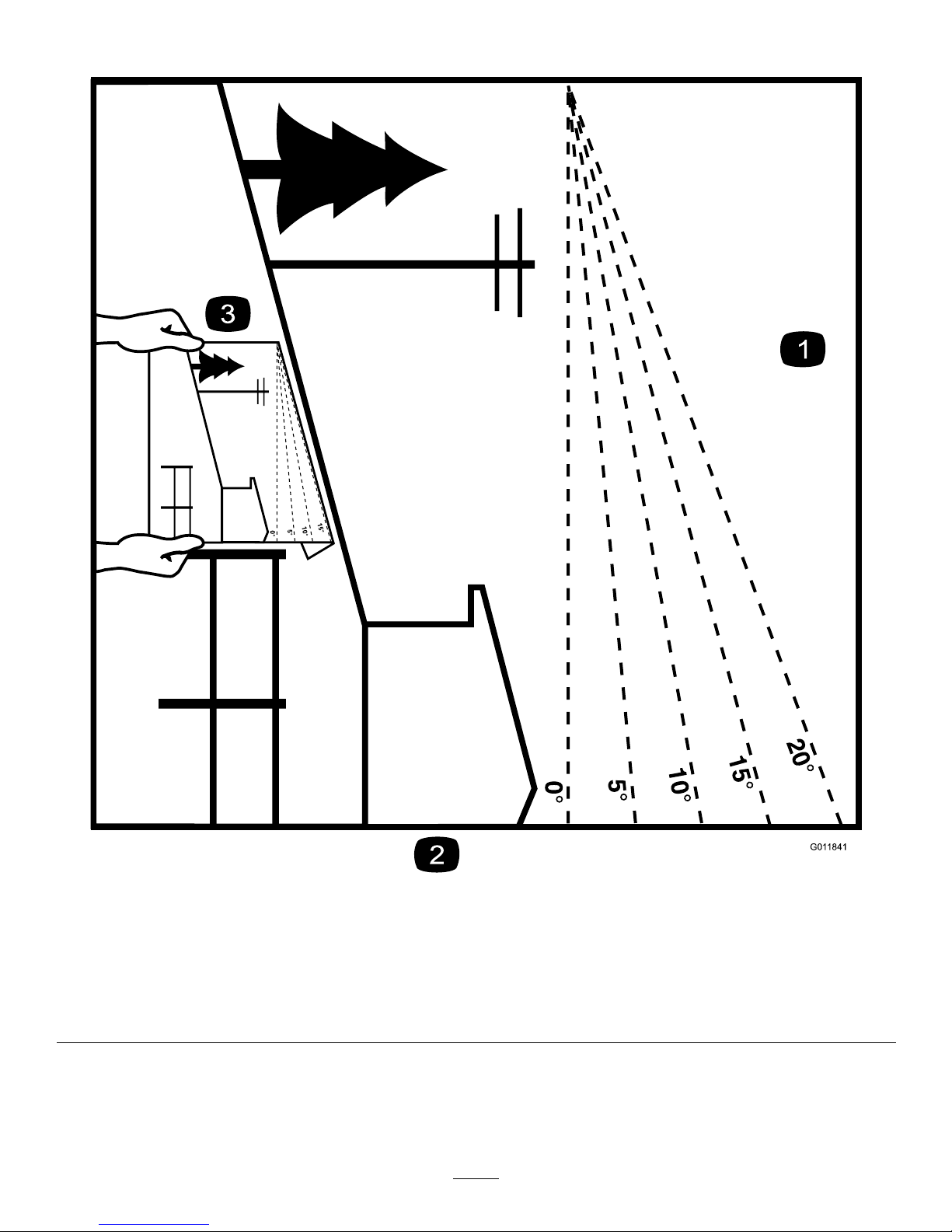
•Donotoperateonaslopegreaterthan20degrees.
•Removeormarkobstaclessuchasrocks,treelimbs,
etc.fromtheoperatingarea.Tallgrasscanhide
obstacles.
•Watchforditches,holes,rocks,dips,andrisesthat
changetheoperatingangle,asroughterraincould
overturnthemachine.
•Alwaysavoidsuddenstartingorstoppingona
slope.Iftireslosetraction,disengagethebladesand
proceedslowlyofftheslope.
•Followtherecommendationsforwheelweightsor
counterweightstoimprovestability.
MaintenanceandStorage
•Waitforallmovementtostopbeforeadjusting,
cleaning,orrepairing.Raisetheblades,stopthe
machine,stoptheengine,anddisconnectthespark
plugwire.
•Cleangrassanddebrisfromtheblades,drives,
mufers,andenginetohelppreventres.Cleanup
oilorfuelspillage.
•Lettheenginecoolbeforestoringanddonotstore
nearame.
•Shutoffthefuelwhilestoringortransportingon
trailers.Donotstorefuelnearamesordrain
indoors.
•Parkthemachineonlevel,hardground.Neverallow
untrainedpersonneltoserviceit.
•Usejackstandsorsafetylatchestosupport
componentswhenrequired.
•Carefullyreleasepressurefromcomponentswith
storedenergy.
•Removethesparkplugwiresbeforemakingany
repairs.
•Keephandsandfeetawayfrommovingparts.If
possible,donotmakeadjustmentswiththeengine
running.
•Keepallpartsingoodworkingconditionandall
hardwaretightened.Replaceallwornordamaged
decals.
•UseonlyLawnSolutions-approvedattachments.
Thewarrantymaybevoidedifthemachineisused
withunapprovedattachments.
4

SlopeIndicator
G01 1841
Figure3
Thispagemaybecopiedforpersonaluse.
1.Themaximumslopeyoucansafelyoperatethemachineonis20degrees.Usetheslopecharttodeterminethedegreeofslope
ofhillsbeforeoperating.Donotoperatethismachineonaslopegreaterthan20degrees.Foldalongtheappropriateline
tomatchtherecommendedslope.
2.Alignthisedgewithaverticalsurface,atree,building,fencepole,etc.
3.Exampleofhowtocompareslopewithfoldededge.
5

SafetyandInstructionalDecals
Safetydecalsandinstructionsareeasilyvisibletotheoperatorandarelocatednearanyareaof
potentialdanger.Replaceanydecalthatisdamagedorlost.
119-4655
112-9028
1.Warning—stayawayfrommovingparts;keepallguardsin
place.
93-7321
1.Cutting/dismembermenthazardofhandsandfeet,rotating
knives—stayawayfrommovingparts.
117–4979
1.Entanglementhazard,belt—stayawayfrommovingparts,
keepallguardsandshieldsinplace.
119-4656
119-4657
6

Setup
UnfoldingtheHandle
1.Raisethehandletotheoperatingposition.
G016884
Figure4
2.Slidetheovallockingringsdowneachsideofthe
upperhandleoverthelowerhandle,lockingthe
handlesectionstogether.
CheckingtheEngineOilLevel
Themachinecomesfromthefactorywithoilinthe
enginecrankcase;however,itmaybenecessarytoadd
oil.RefertoCheckingtheEngineOilLevel(page10).
AddonlyenoughoiltoraisetheleveltotheFullmark
onthedipstick.
TestingtheTransmission
Adjustment
Starttheenginewiththetractioncontrolleverinthe
Neutralposition.Ifthemachinecreepseitherforward
orrearward,stoptheengineandadjustthetransmission
cable;refertoAdjustingtheTransmission(page17).
ProductOverview
G016890
Figure5
1.Cuttingbladescontrol
lever
6.Depthcontrollever
2.Seedercontrollever7.Seedingrategauge
3.Handle8.Seedhopper
4.Tractioncontrollever9.Fueltank
5.Recoilstarterrope
Controls
Figure6
1.Recoilstarter4.Chokelever
2.Sedimentcup5.Throttlelever
3.Fuelshut-offvalve6.EngineOn/Offswitch
7

RecoilStarter
Pulltherecoilstarterhandletostartengine(Figure6).
FuelShut-offValve
Closethefuelshut-offvalvewhentransportingor
storingthemachine(Figure6).
ChokeLever
Beforestartingacoldengine,movethechokelever
forward.Aftertheenginestarts,regulatethechoketo
keeptheenginerunningsmoothly.Assoonaspossible,
movethechokeleverallthewayrearward.
Note:Awarmenginerequireslittleornochoking.
ThrottleLever
Movethecontrolforwardtoincreasetheenginespeed
andrearwardtodecreasespeed.
EngineOn/OffSwitch
TurntoOntoenabletheelectricalsystemandtoOffto
disabletheelectricalsystem.
TractionControlLever
Thetractioncontrollevercontrolstheforward,reverse,
andneutralactionsofthemachine.
•Tomoveforward,pressthecontrolleverforward
(Figure7).Thefurtherforwardyoupushit,the
fasterthemachinewilltravel.
•Tomoveinreverse,pullthecontrolleverrearward
(Figure7).Thefurtherrearwardyoupullit,the
fasterthemachinewilltravel.
•Toturnthemachine,moveslowlyandpressdown
onthehandles;turnthemachineinthedesired
directionthenresumenormaloperation.
•Tostop,releasethecontrollever(Figure7).
12
3
G016885
Figure7
1.Forward3.Reverse
2.Neutral
CuttingBladeControlLever
Holdthecuttingbladecontrolleverdowntothehandle
tostartthecuttingblades.Releasethelevertostopthe
cuttingblades.
G016886
12
Figure8
1.Cuttingbladecontrol
lever—disengaged
2.Cuttingbladecontrol
lever—engaged
DepthControlLever
Thedepthcontrolleverallowsyoutosetthedepthof
thecuttingbladesin1/4inch(6mm)increments.To
adjustthedepth,pullthelockingknoboutandmovethe
8

leverforwardorrearwardtothedesireddepthsetting
(Figure9).
Important:Donotpulltheleverleftorrightasthis
willbendit.
2
Figure9
1.Depthcontrollever2.Lockingknob
Thecenterposition,withthreeopenholestotheleft
oftheleverandfourtotheright)isthezeroposition
withthebladesatthesamedepthasthebottomofthe
wheels.Movetheleverrewardfromtheretoraisethe
bladesabovegroundlevelorforwardtolowertheminto
theground.
g013316
1
Figure10
1.Zeroposition
SeedingRateGauge
Usetheseedrategaugetosettheseedowrate.It
iscalibratedwiththemachinespeedtogiveyouan
evenseedingrateatanyspeed.Tochangetheseeding
rate,loosentheknobonthegaugeandmovethegauge
pointertothedesiredposition,thentightentheknobto
holditinplace.
Figure11
Refertotheseedinggraphlocatedonthemachineto
determinethecorrectgaugesettingforthetypeofgrass
youareplantingandthethicknessinwhichyouwant
toplantit.
SeederControlLever
Pushtheseedercontrollever(Figure12)forwardtostart
theseedowandpullitrearwardtostoptheseedow .
Note:Themachineisdesignedsothattheseedow
slowsand/orstopswhenyoustopthemachineorslow
foraturn.Toreduceseedlossraisethefrontwheelsas
themachineisturned.Thereisnoneedtoturntheseed
owonandoffforeachturn.
1
2
G016887
Figure12
1.Seedercontrollever—Off2.Seedercontrollever—On
9

Specications
Note:Specicationsanddesignaresubjecttochange
withoutnotice.
Width30inches(76cm)
Length(operating)54inches(137cm)
Length(withhandlestored)37.5inches(95.25cm)
Height(operating)44.5inches(113cm)
Height(withhandlestored)29inches(73.5cm)
Weight265lbs(120.2kg)
Operation
Note:Determinetheleftandrightsidesofthe
machinefromthenormaloperatingposition.
CheckingtheEngineOilLevel
ServiceInterval:Beforeeachuseordaily
1.Stopthemachineonalevelsurface.
2.Putthetractioncontrolinneutral,disengagethe
cuttingblades,stoptheengine,waitforallmoving
partstostop,andturnofftheengineswitch.
3.Cleanaroundthedipstick(Figure13)sothatdirt
cannotfallintothellerholeanddamagethe
engine.
Figure13
1.Dipstick
4.Unscrewthedipstickandwipetheendclean
(Figure13).
5.Screwthedipstickfullyontothellertube
(Figure13).
6.Unscrewthedipstickagainandlookattheend.If
theengineoillevelislow,slowlypouronlyenough
oilintothellertubetoraisetheleveltotheFull
markonthedipstick.
Important:Donotoverllthecrankcasewith
engineoilandruntheengine;enginedamage
mayresult.
10

CleaningDebrisfromthe
Machine
ServiceInterval:Beforeeachuseordaily
1.Putthetractioncontrolinneutral,disengagethe
cuttingblades,stoptheengine,waitforallmoving
partstostop,andturnofftheengineswitch.
2.Brushdirtanddebrisawayfromtheaircleanerand
engineopenings.
3.Movetheseedingrategaugeto10andlockitin
place.
4.Movetheseedercontrolleverbackandforthseveral
timestocleartheseederofanydirtanddebrisbuild
up.
AddingFuel
Useunleadedgasoline(87pumpoctaneminimum).
Leaded,regulargasolinemaybeusedifunleadedisnot
available.
Donotusemethanol,gasolinecontainingmethanol,or
gasoholcontainingmorethan10%ethanolbecausethe
fuelsystemcouldbedamaged.Donotmixoilwith
gasoline.
DANGER
Incertainconditions,gasolineisextremely
ammableandhighlyexplosive.Areorexplosion
fromgasolinecanburnyouandothersandcan
damageproperty.
•Fillthefueltankoutdoors,inanopenarea,
whentheengineiscold.Wipeupanygasoline
thatspills.
•Neverllthefueltankinsideanenclosedtrailer.
•Donotllthefueltankcompletelyfull.Add
gasolinetothefueltankuntilthelevelis1/4to
1/2inch(6to13mm)belowthebottomofthe
llerneck.Thisemptyspaceinthetankallows
gasolinetoexpand.
•Neversmokewhenhandlinggasoline,andstay
awayfromanopenameorwheregasoline
fumesmaybeignitedbyaspark.
•Storegasolineinanapprovedcontainerand
keepitoutofthereachofchildren.Neverbuy
morethana30-daysupplyofgasoline.
•Donotoperatewithoutentireexhaustsystem
inplaceandinproperworkingcondition.
DANGER
Incertainconditionsduringfueling,static
electricitycanbereleasedcausingasparkwhich
canignitethegasolinevapors.Areorexplosion
fromgasolinecanburnyouandothersandcan
damageproperty.
•Alwaysplacegasolinecontainersontheground
awayfromyourvehiclebeforelling.
•Donotllgasolinecontainersinsideavehicle
oronatruckortrailerbedbecauseinterior
carpetsorplastictruckbedlinersmayinsulate
thecontainerandslowthelossofanystatic
charge.
•Whenpractical,removegas-powered
equipmentfromthetruckortrailerandrefuel
theequipmentwithitswheelsontheground.
•Ifthisisnotpossible,thenrefuelsuch
equipmentonatruckortrailerfromaportable
container,ratherthanfromagasolinedispenser
nozzle.
•Ifagasolinedispensernozzlemustbeused,
keepthenozzleincontactwiththerimofthe
fueltankorcontaineropeningatalltimesuntil
fuelingiscomplete.
UsingStabilizer/Conditioner
Useafuelstabilizer/conditionerinthetractionunitto
providethefollowingbenets:
•Keepsgasolinefreshduringstorageof90daysor
less.Forlongerstorageitisrecommendedthatthe
fueltankbedrained.
•Cleanstheenginewhileitruns
•Eliminatesgum-likevarnishbuildupinthefuel
system,whichcauseshardstarting
Important:Donotusefueladditivescontaining
methanolorethanol.
Addthecorrectamountofgasstabilizer/conditioner
tothegas.
Note:Afuelstabilizer/conditionerismosteffective
whenmixedwithfreshgasoline.Tominimizethe
chanceofvarnishdepositsinthefuelsystem,usefuel
stabilizeratalltimes.
FillingtheFuelTank
1.Putthetractioncontrolinneutral,disengagethe
cuttingblades,stoptheengine,waitforallmoving
partstostop,andturnofftheengineswitch.
2.Allowtheenginetocool.
11

3.Cleanaroundthefueltankcapandremoveit
(Figure14).
Note:Thecapistetheredtothefueltank.
g013315
Figure14
4.Addunleadedgasolinetothefueltank,untilthe
levelisjustinsidethemeshlterbasket.
Important:Thisspaceinthetankallows
gasolinetoexpand.Donotllthefueltank
completelyfull.
5.Installthefueltankcapsecurely.
6.Wipeupanygasolinethatmayhavespilled.
StartingandStoppingthe
Engine
StartingtheEngine
1.Ensurethatthetractioncontrolleverisinneutral
andthatthecuttingbladecontrolleverisoff.
2.MovetheengineswitchtotheOnpositionandturn
onthefuelvalve.
3.Movethechokelevertotheleftifyouarestarting
acoldengine.
4.Movethethrottlelevermidwaybetweenslow
(turtle)andfast(rabbit)positions.
Note:Awarmorhotenginemaynotrequire
choking.
5.Pulltherecoilhandlesharplytostarttheengine.
6.Aftertheenginestarts,graduallymovethechoketo
theright.Iftheenginestallsorhesitates,movethe
chokeleftagainuntiltheenginewarmsup.
7.Movethethrottlelevertodesiredsetting.
StoppingtheEngine
1.Turntheengineswitchandfuelvalveoff.
2.Waitforallmovingpartstostopbeforeproceeding.
OperatingtheMachine
1.Ifseeding,settheseedingrategaugetothedesired
rate.
2.Movethedepthcontrollevertothedesiredsetting.
3.Ensurethatthetractioncontrolleverisinneutral.
4.Starttheengine.
5.Pushdownonthehandletoraisethefrontwheels
offoftheground.
6.Pullthecuttingbladecontrollevertothehandle
andslowlylowerthefrontwheelstotheground,
allowingthebladestograduallyworkintothegrass
andsoil.
7.Ifseeding,pushtheseedercontrolleverforward.
8.Movethetractioncontroltothedesiredspeedand
direction.
9.Whennished,placethetractioncontrollever
inneutral,pulltheseedercontrolleverrearward,
releasethecuttingbladecontrollever,stopthe
engine,andraisethecuttingbladestothehighest
setting.
OperatingTips
PowerSeeding
Whenoverseeding,setthecuttingbladestobe1/8to
1/4inch(3to6mm)intotheearth(belowthezero
position).Forbasicseeding,onlymakeonepass.If
thereareafewbadareas,suchasfungusdamageordog
urine,seedtheentirepropertyasnormal,butstopafter
eachbadspot,backuppastitagain,andthenresume
overit,effectivelyseedingitwithtripletheamountof
seed.
Important:Donotputdownmoreseedthan
recommendedbytheseedcompany.Overseeding
cancausethegrasstobetoothickandcauseitto
besusceptibletofungus.
Note:Themachinewillseedatthesamerategoing
bothforwardandrearward.
Note:Ifthereisexcessivethatch,itmaybenecessary
toremovethethatchpriortoseeding.
Dethatching
Setthecuttingbladestobe1/8to1/4inch(3to6
mm)intotheearth(belowthezeroposition).Operate
12

themachineovertheyardwiththeseedercontrollever
turnedoff.
Note:Dethatchanewlyseededlawnthefollowing
springorfalltoallowthegrasstothickenandreduce
thechanceoffungus.
PowerRaking/Renovation
Tobreaknewgroundortillanexistinglawn,setthe
cuttingbladestobe1/4to1/2inch(6to12mm)into
theearth(belowthezeroposition).Allowthemachine
toprogressatitsownpacethroughthesoil,going
forwardandbackwardsovertheareatobeleveled,or
makingmultiplepassesfromdifferentdirections.
Themachinewillworkbestwhenthegroundishard
anddryandwillbemostaggressiveinbreakingupthe
soilinreverse.Ifthegroundissoftandcausesthe
enginetobogdown,raisethebladesabitandmakea
fewpassesbeforeloweringthemtothefulldepth.
13

Maintenance
RecommendedMaintenanceSchedule(s)
MaintenanceService
IntervalMaintenanceProcedure
Beforeeachuseordaily
•Checktheengineoillevel.
•Cleandebrisfromtheaircleanerandseedbasket.
•Inspecttheaircleanerelements.
•Checkthetirepressure.
•Ensurethatthemachinedoesnotcreepwhenthetractioncontrolleverisinneutral.
•Checkthetransmissiondrivebeltforsquealing.
•Checkthattheseedgatecloses.
•Checkthebladesforwearordamage.
•Checkforloosefasteners.
Every50hours•Cleantheairlterelements.Cleanthemmorefrequentlyindustyoperating
conditions.
Every100hours•Inspect,clean,andadjustthesparkplug;replaceitifnecessary.
Every200hours•Replacethesparkplug.
Every300hours•Replacethepaperaircleanerelement.Replaceitmorefrequentlyindustyoperating
conditions.
Yearlyorbeforestorage•Touchupchippedpaint
Premaintenance
Procedures
DisengagingtheHydrostatic
Drive
Ifyouneedtopushthemachineunpowered,youmust
releasethehydrostaticdrive.Toreleasethedrive,pull
thedrivebypassleveroutandup,lockingitintheout
position(Figure15).Thefrontwheelswillnowrotate.
Toengagethedrive,pushdownonthebypassleveruntil
itsnapsbackintothemachine.
Figure15
1.Drivebypasslever—disengaged
2.Drivebypasslever—engaged
14

DisconnectingtheSparkPlug
Wire
Beforeperforminganymaintenanceontheengine,belts,
orcuttingblades,disconnectthesparkplugwirefrom
thesparkplug(Figure16).
Figure16
1.Sparkplugwire
EngineMaintenance
ServicingtheAirCleaner
ServiceInterval:Beforeeachuseordaily—Inspectthe
aircleanerelements.
Every50hours—Cleantheairlter
elements.Cleanthemmorefrequently
industyoperatingconditions.
Every300hours/Yearly(whichever
comesrst)—Replacethepaper
aircleanerelement.Replaceit
morefrequentlyindustyoperating
conditions.
Important:Donotoperatetheenginewithoutthe
airlterassembly;extremeenginedamagewill
occur.
1.Stoptheengineandwaitforallmovingpartstostop.
2.Disconnectthewirefromthesparkplug.
3.Removethenutthatsecuresthecover(Figure17).
Figure17
1.Nut4.Foamelement
2.Cover5.Base
3.Paperelement
4.Removethecover.
Note:Becarefultopreventdirtanddebrisfrom
fallingintothebase.
5.Removethefoamandpaperelementsfromthebase
(Figure17).
6.Removethefoamelementfromthepaperelement
(Figure17).
7.Inspectthefoamandpaperelements,andreplace
themiftheyaredamagedorexcessivelydirty.
15

8.Ifthepaperelementisexcessivelydirty,replaceit.
Note:Nevertrytobrushdirtoffthepaperelement;
brushingforcesthedirtintothebers.
9.Cleanthefoamelementinwarm,soapywaterorina
nonammablesolvent.
Note:Donotusegasolinetocleanthefoam
elementbecauseitcouldcreateariskofreor
explosion.
10.Rinseanddrythefoamelementthoroughly.
11.Dipthefoamelementincleanengineoil,then
squeezeouttheexcessoil.
Note:Excessoilinthefoamelementrestrictsthe
airowthroughtheelementandmayreachthe
paperlterandclogit.
12.Wipedirtfromthebaseandthecoverwithamoist
rag.
Note:Becarefultopreventdirtanddebrisfrom
enteringtheairductleadingtothecarburetor.
13.Installtheaircleanerelementsandensurethatthey
areproperlypositioned.
14.Securelyinstallthecoverwiththenut.
ServicingtheEngineOil
OilType:Detergentoil(APIserviceSJorhigher)
CrankcaseCapacity:1.16USqt(1.1l)
Viscosity:Seetablebelow
Figure18
CleaningtheSedimentCup
DANGER
Incertainconditions,gasolineisextremely
ammableandhighlyexplosive.Areorexplosion
fromgasolinecanburnyouandothersandcan
damageproperty.
•Stoptheengineandkeepheat,sparks,and
ameaway.
•Handlefuelonlyoutdoors.
•Wipeupspillsimmediately.
•Donotsmokewhilehandlingfuel.
1.Movethefuelshut-offvalvetotheOffposition.
2.RemovethesedimentcupandO-ring(Figure6).
3.Washthesedimentcupinanonammablesolvent
anddryitthoroughly.
4.PlacetheO-ringinthefuelvalveandinstallthe
sedimentcup,tighteningitsecurely.
5.Movethefuelshut-offlevertotheOnposition.
Ifanyfuelleaks,repeatthisprocedureandreplace
theO-ring.
ServicingtheSparkPlug
ServiceInterval:Every100hours—Inspect,clean,
andadjustthesparkplug;replaceitif
necessary.
Every200hours—Replacethespark
plug.
UseanNGKBPR6ESsparkplugorequivalent.
1.Stoptheengineandwaitforallmovingpartstostop.
2.Disconnectthewirefromthesparkplug.
3.Cleanaroundthesparkplug.
4.Removethesparkplugfromthecylinderhead.
Important:Replaceacracked,fouled,or
dirtysparkplug.Donotcleantheelectrodes
becausegritenteringthecylindercandamage
theengine.
5.Setthegapontheplugto0.030inch(0.76mm)
(Figure19).
16

Figure19
1.Centerelectrodeinsulator
2.Sideelectrode
3.Airgap(nottoscale)
6.Carefullyinstallthesparkplugbyhand(toavoid
crossthreading)untilitishandtight.
7.Tightenthesparkpluganadditional1/2turnifitis
new;otherwise,tightenitanadditional1/8to1/4
turn.
Important:Aloosesparkplugcanbecomevery
hotandcandamagetheengine;overtightening
asparkplugmaydamagethethreadsinthe
cylinderhead.
8.Connectthewiretothesparkplug.
DriveSystem
Maintenance
CheckingtheTirePressure
ServiceInterval:Beforeeachuseordaily
Maintaintheairpressureinthetiresasspecied.Check
thetireswhentheyarecoldtogetthemostaccurate
reading.
Pressure:46psi(317kPa)
1
G003793
Figure20
1.Valvestem
AdjustingtheTransmission
ServiceInterval:Beforeeachuseordaily—Ensurethat
themachinedoesnotcreepwhenthe
tractioncontrolleverisinneutral.
Ifthemachinecreepseitherforwardorrearwardwhen
theengineisonandthetractioncontrolleverisin
neutral,completethefollowingprocedure:
1.Stopthemachineonalevelsurface,placethe
tractioncontrolleverinneutral,stoptheengine,and
raisethecuttingbladestothehighestposition.
2.Loosenthenutsonthetransmissioncontrolcable
underthetractioncontrolhandle(Figure21).
17

g016888
1
2
Figure21
1.Jamnut2.Cable
3.Movethecabledowntostopforwardmovementor
uptostopreversemovement.
4.Tightenthejamnuts.
5.Starttheengineandtesttheadjustment,repeating
thisprocedureasnecessaryuntilthemachinedoes
notmovewhenthetractioncontrolhandleisin
neutral.
BeltMaintenance
AdjustingtheTransmission
DriveBeltTension
ServiceInterval:Beforeeachuseordaily—Checkthe
transmissiondrivebeltforsquealing.
Ifthetransmissiondrivebeltsquealsduringoperation
(i.e.,whenyoushiftfromneutraltoforwardorreverse),
tightenthebeltasfollows:
1.Stopthemachineonalevelsurface,placethe
tractioncontrolleverinneutral,stoptheengine,
disconnectthesparkplugwire,andraisethecutting
bladestothehighestposition.
2.Removethe3bolts,lockwashers,and2spacers
securingthebeltcovertotheleftsideofthemachine
andremovethecover.
3.Checkthetensionofthetransmissiondrivebelt.It
shouldnotexmorethana1/2inch(12mm)with
moderatengerpressureappliedtothespanjust
abovethemachineframe.
g016901
Figure22
4.Totightenthebelt,loosenthefourmounting
nuts/boltssecuringthepulleycarriagetotheframe
andmovethecarriagetotheleft,tighteningthebelt,
thensecurethefourmountingnutsandbolts.
Ifyoucannotattainthenecessarytensionbecause
thecarriageisushwiththesideoftheframe,
completethefollowingtolowerthecarriageslightly:
A.Loosenthenuts/boltssecuringthecarriage.
B.SlidefourC-washersoverthemountingbolts
betweenthepulleycarriageandtheframe.
18

g016900
1
1
2
3
4
2
5
Figure23
1.Nutandwasher4.C-washer
2.Pulleycarriage5.Bolt
3.Machineframe
C.Movethecarriagetotheleft,tighteningthebelt,
thensecurethefourmountingnutsandbolts.
5.Installthebeltcoverusingthefastenersyouremoved
previously.
SeederMaintenance
AdjustingtheSeedGate
ClosedPosition
ServiceInterval:Beforeeachuseordaily—Checkthat
theseedgatecloses.
Iftheseedgateispartiallyopenwhentheseedercontrol
leverisintheOffposition,completethefollowing:
1.Stopthemachineonalevelsurface,placethe
tractioncontrolleverinneutral,stoptheengine,and
raisethecuttingbladestothehighestposition.
2.PulltheseedercontrollevertotheOffposition.
3.Loosenthenutsontheseedgatecontrolcable
(Figure24).
g013391
12
Figure24
1.Jamnut2.Cable
4.Movethecablerighttoclosetheseedgateorleft
toopenit.
Important:Donottightenthecabletothepoint
theseedgateistighttotherightwithextreme
tensiononthecableasthiswilldamagethe
gateandthecable.Onlyadjustitjustuntilthe
openingsinthebottomoftheseederareclosed.
5.Tightenthejamnutsandtesttheseedercontrol
levertoensurethattheseedgateopensandcloses
correctly.
19

ReplacingWornCutting
Blades
ServiceInterval:Beforeeachuseordaily—Checkthe
bladesforwearordamage.
Whenthecuttingbladesareworndownandnolonger
functioningproperly,replacethem,asfollows:
Important:Performthisprocedurewhenthefuel
tankisemptyornearlyempty.
1.Stopthemachineonalevelsurface,placethe
tractioncontrolleverinneutral,stoptheengine,and
raisethecuttingbladestothehighestposition.
2.Removethe3bolts,lockwashers,and2spacers
securingthebeltcovertotheleftsideofthemachine
andremovethecover.
3.Removethecuttingbladesdrivebeltfromthe
machine.
4.Tiltthemachineforwardontoitsnose,restingona
blockofwood.
Note:Itwilltaketwopeopletotipthemachine
forwardsafely.
5.Lowerthecuttingbladestothelowestposition.
6.Spinthecuttingbladeassembly.Itshouldspinfreely.
Ifitmakeagrindingnoiseandishalting,thebearings
areworn;replacethemwhenyoureplacetheblades.
7.Removethe4carriageboltsandlocknutssecuring
thecuttingbladeassembly(Figure25)andremoveit
fromthemachine.
g013392
1
2
3
5
6
7
89
10
11 4
Figure25
1.Bolt7.Largenut
2.Pulleywheel8.Washer
3.Carriagebolt9.Cuttingblade
4.Setscrew10.Spacer
5.Bearing11.Shaft
6.Locknut
8.Removethe2boltsattachingthepulleywheeltothe
assembly(Figure25).
9.Loosenthe2setscrewslocatedonthebearing
(Figure25)andslidethebearingoffoftheshaft.
10.Loosenandremovethelargenutandwasherfrom
theshaft(Figure25).
11.Slidethespaceroffoftheshaft(Figure25).
12.Carefullyslidethebladesoffoftheshaft(Figure25)
andreplacethemasnecessary.
13.Reversetheproceduretoinstalltheassembly.
20
Table of contents
Other Lawn Solutions Lawn And Garden Equipment manuals