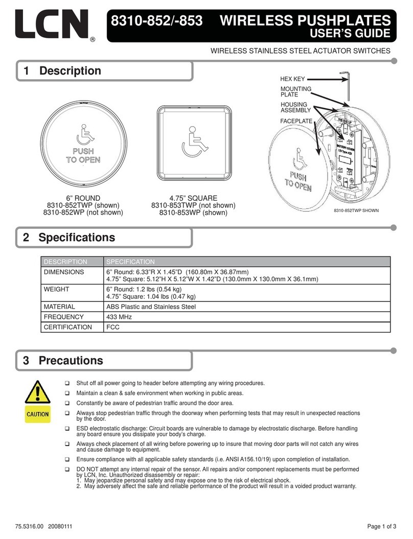
LCN 8310-2210 Series User manual

Model 8310-2210 Installation Instructions
Description
Actuator
Available faceplates:
Single gang: 2-3/4” x 4-1/2” stainless steel, fits on single gang electrical boxes.
Receiver
• 3 Modes of Operation:
• Delayed (1 - 15 Seconds)
• No Delay (1 – 30 Seconds)
• Latching
• Adjustable Range: 3’ - 300’
• 40 Transmitter capacity: delayed, non-delayed or both
• Form ‘C’ Relay Output
• 12/24V AC/DC operation
• 915 MHz
• Dimensions: 2-5/8” x 1-1/2” x
13/16”
Technical specifications
Actuators
Descriptions 8310-2210 Series
Number of IR sensors 1
Batteries (supplied) “AA” alkaline batteries
Estimated battery life 2 years (based on 100 operations/day)
Standard operating range 1” - 12” (25.4mm - 304mm)
Factory set to 6” (152mm)
Operating mode Momentary
Inputs “Request to Exit” (to trigger the relay remotely or from the other side of the door)
Wireless output Built-in 915 Mhz. spread spectrum wireless transmitter
Receivers
Descriptions 8310-2210 Series
Operating voltage 12/24V AC/DC
Current Draw 23 mA nominal @ 24V AC/DC
43 mA maximum @ 24V AC/DC
Response time 30 - 200 ms
Memory delay & No delay 40 transmitters total
LEDs Indicate: relay status; learn mode; erase mode; and potentiometer position
Output 1 x SPDT relay contact
Rating 3 amps @ 30 VDC
Operating time 1 - 30 seconds
Delay time 1 - 15 seconds
Frequency 915 Mhz
Mounting 2 #4 screws at 3” centers or hook and loop fastener (supplied)
Enclosure Clear plastic case
Dimension 2-5/8” x 1-1/2” x 13/16”
8310-2210 Series Touchless Actuator/
Transmitter Battery Powered Contactless Switch

Installation
1 Mounting
Actuators
The touchless actuator may be mounted in conventional plastic electrical gang boxes. Ensure that the unit sensor does
not come in contact with any metal components within the gang box to avoid shorting out the unit.
Do not place the sensor in the door’s opening range, where the sensor may see door movement. Do not place moving
objects in front of the sensor.
Use the weather resistant gasket as a protective barrier against the elements.
For electrical box installation, refer to the mounting box instructions that come with the product.
LNOTE: Actuators are recommended for interior use only!
1a If using an in-wall box ensure the box is plumb and square, and flush with the wall surface.
If using a surface box, ensure it is secure & plumb.
1b Using the dip switch located on the end of the unit, set the operating mode. (See Section 3: Setup).
1c Attach the unit to the enclosure using the two #6-32 screws provided.
1d Attach the faceplate to the unit using the two black #6-32 x 3/8 machine screws or tamperproof screws.
LNote: Do not overtighten!
Receivers
The receiver is designed to mount under the cover or in the header, depending on the model. Screw holes are located at
each end of the receiver case, or the included hook and loop fastener may also be used to hold it securely.
2 Wiring
CAUTION
Do not apply power to the unit until all secondary wiring is complete, and dip-
switches have been set.
Actuators
The actuator is powered from 2 AA batteries (supplied). The battery holder has been pre-installed. Insert the batteries into
the battery holder. Please be careful that the polarity of the batteries is correct.
TRANSMITTER
Request To
Exit Input
Power In -
Power In +
Diagram 1

Receivers
LNOTE: Do not use the receiver as a safety device! If safety devices are used, always wire directly to the operator
control box.
LNOTE: For installation/use with the 6440 Compact Series, use the provided 4-wire wiring harness.
The receiver output is a form “C” relay. Selecting the correct output is also dependent on the operating mode chosen. Most
applications will utilize the N.O. and Common terminals.
Refer to the wiring diagram in the provided actuator instructions, and wire the receiver as follows:
Wire the device (electric lock / operator) to the Relay output - terminal 3 is N.O. 4 is Common and 5 is N.C.
Connect 12 or 24V AC/DC to terminals 1 & 2 on the receiver. (Terminals are not polarity sensitive).
Terminal Description
1 Power in
2 Power in
3 Normally open
4 Common
5 Normally closed
3 Set-up
Actuators
Dip Switch Settings
See the diagrams below for the dip switch locations:
Dip Switch Bank 1 Dip Switch Bank 2
8310-2200
Series
Description Function SW1 SW2 Description
1 LED Enable Green LED flashes while
the output is activated
Momentary OFF OFF The output operates
once and only re-
engages aer the
object is removed.
2 Audio Enable Piezo buzzer sounds
when the output is
activated
Momentary
with alarm
ON OFF The output operates
once, and only re-
engages aer the
object is removed.
If an object remains
in the detectable
area, an alarm will
generate aer about
30 seconds.
Continuous
operation
OFF ON The output remains
activated until the
object is removed.
Switch 1 - LED On/LED Off
This switch disables the LED, should this feature be desired. Factory setting is
OFF. This feature will decrease the battery life if set to ON.
Switch 2 - Audio Enable
Set this switch to ON to enable an audible beep every time the switch is
activated. The factory default is OFF. Enabling this feature will use additional
power and decrease the life of the battery.
O
N
12
124
3
Activate
LED
Sounder
Error/Alarm
LED
Range Adj.
LED Enable
Audio Enable
MOM OP
MOM OP with Alarm
O
N

Battery strength meter
To check the battery strength, place an object in front of the
actuator for about 5 seconds. The actuator will beep up to five
times, indicating the batter charge level. Five beeps will mean that
the battery is fully charged. One to three beeps will mean that you
should change the batteries.
Adjustments
Once the dip switches have been set, and the unit is installed in
the frame or enclosure, apply power to the unit and observe the
operation.
Set potentiometer to minimum setting initially (fully counter-
clockwise).
Adjust the range potentiometer by turning the pot in a clockwise
manner, and passing your hand in front of the unit. Rotate the
pot until the desired range is obtained. See the diagram on the
previous page for locations.
Receivers
1 The kit comes pre-paired for immediate use. For any other application and/or addition of sensors, see the pairing
process below.
Pairing the transmitter(s) to the receiver
A receiver can have up to 40 transmitters paired with it. The transmitter can be paired as delayed, non-delayed or a
combination of both, making the transmitter ideal for bi-directional door sequencing.
2
ON
1
POT1 PB1
DIP 1
DIP 2
Set the RF Transmitter Type
Always set DIP2 to OFF for proper function.
Pairing the Transmitter in Delayed Mode
Set DIP1 to ON.
Press PB1 using a small blunt object such as a small blade screwdriver or similar. Within 10 seconds, press the switch
connected to 8310-2210 actuator. The Green LED Array flashes to confirm enrollment. Repeat with any additional
transmitters. Pressing the paired transmitter again will signal the receiver that you are finished programming and the LED
will flash rapidly.
Pressing the transmitter a third time activates the relay, LED, and the device connected to the relay contacts aer the delay
time set by POT1. If you wait longer than the 10 second period, the receiver times out of Pairing Mode and reverts back to
standby.
Pairing the Transmitter in No-Delay Mode
Set DIP1 to OFF
Press PB1 using a small blunt object such as a small blade screwdriver or similar. Within 10 seconds, press the switch
connected to 8310-2210 actuator. The Green LED Array flashes to confirm enrollment. Repeat with any additional
transmitters. Pressing the paired transmitter again signals the receiver that you are finished programming and the LED will
flash rapidly.
Pressing the transmitter a third time will activate the relay, LED, and the device connected to the relay contacts. If you wait
longer than the 10 second period, the receiver times out of Pairing Mode and reverts back to standby.
2
Adjustments
The delay before operate and relay On-Time are controlled by POT1.
Delayed mode
The receiver has a delay before operate timer.
Set DIP1 to ON.
1’
0’ 2’
3’
1”
(25.4mm)
12”
(304mm)

Adjust POT1 clockwise to increase the delay timer from 0 to 15 seconds. The LED lights and become brighter as the delay
time is increased and becomes dim as the delay time is decreased. The LED starts to flash once the maximum delay time
has been reached. Back off the delay time until the LED is solid again for maximum delay time.
No-delay mode
The receiver can be adjusted to activate the output relay without a delay. The relay On-Time is adjustable from 1 to 30
seconds.
Set DIP1 to OFF.
Adjust POT1 Clockwise/counterclockwise to adjust the relay On-Time (1 to 30 Seconds). To increase the time, turn the pot
clockwise, or for minimum time, turn the pot counterclockwise.
The LED lights and becomes brighter as the Relay On-Time is increased. The LED starts to flash once the maximum On-
Time has been reached. Back off the POT until the LED is solid again for maximum On-Time.
Toggle mode
The receiver has a toggle mode. Activating the transmitter will latch the output relay ON. Activating the transmitter a
second time will latch the Relay OFF.
DIP1 can be set to either ON/OFF.
Adjust POT1 clockwise until the LED starts to flash. The receiver is in toggle mode at this point. To remove toggle mode,
turn POT1 counter clockwise until the LED is solid again.
LNote: Toggle mode disables delayed mode. Transmitter programmed as delayed mode will work as toggle mode
transmitter.
Signal strength adjustment
For the most reliable, consistent operation, leave the signal strength at full power. The receiver has an adjustment RF range
from a few feet to full range (300 . LOS).
To adjust the RF range:
1. Press PB1 to enter pairing mode.
2. Press PB1 again until the LED flickers 3 times. This places the receiver in RF range adjust mode.
3. Adjust POT1 to adust the RF range. CW to increase the range, CCW to decrease the range.
4. Press a paired transmitter to test range as it is being adjusted.
5. Once the desired range is set, Press and hold PB1 until LED flickers 3 times. The transmitter is now back in pairing mode.
Either wait for the receiver to time out or press a paired transmitter to exit pairing mode. Aer adjusting the range you
MUST adjust POT 1 for relay timing at this point based on the mode (delay or no-delay).
3 Deleting transmitters
Delay mode transmitters
Set DIP1 to ON.
Pressing and holding PB1 for 8 seconds deletes all transmitters delay mode. LED flashes rapidly for 4 seconds, indicating
erasure of the codes.
No delay mode transmitters
Set DIP1 to OFF.
Pressing and holding PB1 for 8 seconds deletes all transmitters no delay mode. The LED flashes rapidly for 4 seconds,
indicating erasure of the codes.
LNote: Individual removal of specific codes is not possible.

Troubleshooting
Door does not open when swiping
hand in front of sensor
Bad or no power Check power supply. If LED switches
on or flashes, power connections are
okay.
Detection range too short Adjust detection zone. Remove any
metal plates in front of sensor.
Incorrect wiring/connection Check wiring and relay connection.
Sensor stays in detection Environmental conditions influencing
sensor
Remove moving objects from around
sensor.
Incorrect wiring/connection Check wiring and relay connection.
Door remains open aer detection/
activation
Wrong output mode Switch output mode to Pulse.
Incorrect wiring/connection Check wiring and relay connection.
Weak signal Receiver antenna wire is poorly
positioned
Position antenna outside of door
header.
Unable to program Stuck actuation or faulty transmitter Disconnect each push plate until
LED goes out. Verify DIP 1 is on (LED
activation signal ON).
Faulty actuator/transmitter Check battery strength (check battery
strength meter). Remove & replace
batteries. Replace faulty actuator/
transmitter assembly.
No activation Power wires not connected Verify power connect at actuator/
transmitter touchless plate, and power
source.
Activation wires not connected Verify activation connection at
actuator/transmitter and door control.
Receiver not programmed Set up actuator/transmitter.
Constant activation Something is moving in front of the
touchless plate
Actuator/transmitter alarm will sound.
Verify DIP positions SW1 (ON) & SW2
(OFF).
Clear the area around the plate.
Transmitter connected to NC of
touchless sensor
Connect to NO.
Receiver set to Toggle Mode Turn POT 1 counterclockwise until
receiver LED is solid.

© Allegion 2021
Printed in U.S.A.
47375846 Rev. 07/21-a
Do not leave problems unresolved. If a satisfactory solution cannot be achieved aer troubleshooting a problem,
please contact Allegion at 1-877-671-7011. If you must wait for the following work day to call Allegion, leave the door
inoperable until satisfactory repairs can be made. Never sacrifice the safe operation of the automatic door or gate for
an incomplete solution.
For more information, visit www.allegion.com.
Wiring diagrams
7900 Series
Pneumatic Auto-Equalizer
RED
BLACK
WHITE
GREEN
1 2 3 4 5
12/24V
AC/DC
NO
COM
NC
6 7 8 9 10 11 12
13 14 15 16 17 18 19 20 21 22 23 24
4630/4640 Series
Electric Auto-Equalizer
ACTUATOR/
TRANSMITTER
RECEIVER
9100 Series
Benchmark
-24 VDC
+24 VDC
SAFETY SEN
SAFETY GND
RELAY COM
RELAY N/O
RELAY N/C
AUX GND
AUX ACT
3-WAY HO
3-WAY GND
3-WAY OFF
MAIN ACT
MAIN ACT
RED
BLACK
WHITE
GREEN
12/24V
AC/DC
NO
COM
NC
ACTUATOR/
TRANSMITTER
RECEIVER
24V
TRANSFORMER
120V
345678910
ACTUATOR/
TRANSMITTER
RED
BLACK
WHITE
GREEN
12/24V
AC/DC
NO
COM
NC
RECEIVER
2800/9500 Series Senior Swing
P1
P2
P3
P4
P5
P6
P7
P8
P9
BLACK
WHITE
YELLOW
GRAY
ACTUATOR/
TRANSMITTER
12/24V
AC/DC
NO
COM
NC
RECEIVER
RED
BLACK
WHITE
GND
+24V DC
COMMON
ACTUATE
GREEN
12/24V
AC/DC
NO
COM
NC
6440 Compact Series
ACTUATOR/
TRANSMITTER
RECEIVER
Table of contents
Other LCN Controllers manuals
Popular Controllers manuals by other brands

Mitsubishi Electric
Mitsubishi Electric Central Controller G-50A installation manual

HomeMatic
HomeMatic HM-LC-Sw1-DR Installation and operating manual

Dakota Digital
Dakota Digital PAC-2700 manual

PI
PI E-727 user manual

Texas Instruments
Texas Instruments bq34z100 user guide

YOKOGAWA
YOKOGAWA UT520 user manual