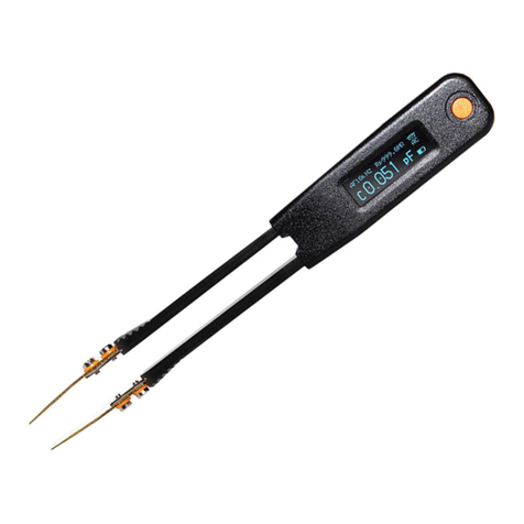
LCR LQ-9101 User manual

LQ-9101 User Manual
Chapter 1 The General Description
LQ-9101 is a compact LCR measurement instrument that uses the principle of free axis impedance
measurement VI parallel processing and modern components. It has the characteristics of small size
light weight high precision low power consumption and fast measurement speed. It is suitable for
electronic test design electrical maintenance and other occasions to facilitate rapid measurement and
analysis of component performance.
1.1 Basic Performance
Measurement Source Frequency 0Hz(DC) 100Hz 120Hz 1000Hz 10KHz Error ±100PPM
Voltage DC: 0.56V±5%
AC AC RMS: 100mV 300mV 600mV ±5%
Internal Resistance AC DC Constant 100Ω ±5%
Basic Accuracy ± Reading × 0.2%
Measurement Display Range
Resistance 000.0 mΩ—1000 MΩ
Q: 0.000—9999 D: 0.0000—9999.9 θ: -180.00°-- +180.00°
Minimum Resolution
Rs/Rp/Z 0.1 mΩ
100Hz120Hz 0.1P 0.1uH
1000Hz 0.01P 0.01 uH
10KHz 0.001P 0.001uH
Display Valid Digit
Measurement Status Four Valid Digit
Test Status Five Valid Digit
Display
Window 43×29 mm Eective Display Area 37×23 mm
LCD128×64 Automatic Backlight
Update Frequency 3.75Hz
Measurement Terminal
Body Built-in Spring Clip jack: Direct measurement
of the external test socket: Suitable for 3.5mm stereo headphone plug test line Ф
Measurement connection method
Body reed clip jack: Four-wire mode
External test line: Four-wire mode
measurement result display and model
resistance inductance capacitance Q value D value phase angle
Ls(Cs)-Rs-Q model Lp(Cp)-Rp-D model Z-θ model
measurement time
from the of the measured component the main parameter is about 1 second parameter ≥1 second
power supply and a charging
Set 3.7V / 450mAH rechargeable polymer lithium ion battery
2017/06/01 VER.H VER.K Page 1/22

LQ-9101 User's Manual
normal operating voltage of > 3.5 ± 0.1V when the normal operating voltage of the bridge is lower than
the boot can not be
Charging power supply DC5V 3.5mm inner and outer core plugs inner + outer - charging time of Ф
about 2 hours
The power consumption of
the power consumption of maximum27mA (dark ambient backlight automatic adjustment of the brightest
non-test state)
Basic operating current 23mA (light environment backlight automatically adjust the most Dark non-test
state)
Power OFF state consumption < 1uA Automatic shutdown time
15 ± 2 minutes automatic shutdown pre-reminded time 1 minute The maximum size and weight of
the whole machine 103 × 69 × 24 mm 180g
1.2 Panel function conguration
shown in Figure 1 Each functional part of the instrument (charging jack charging indicator power
switch on the top side and external test cord outlet on the lower side)
Fig. 1
2017/06/01 VER.H VER.K Page 2 of 22

LQ-9101
User Manual
1.3 Display interface description
Figure 2 shows the integrated display interface. The content description is shown in the
gure.
Figure 2
Figure 3 is the Z-θ display interface and the interface mark is the lower right corner Z. For the □
description of the content see the
gure 3
2017/06/01 VER.H VER.K Page 3 of 22

LQ-9101
User Handcopies
FIG 4 is a tandem parameter interface the interface is marked as the lower right corner S see gure □
Description
4
5 is parallel parameter interface the interface is the lower right corner ag P illustrated5 see □
Description
in FIG.
2017/06/01 VER.H VER.K Page 4 of 22Section 2

LQ-9101 User Manual
Complex Impedance and Equivalent Circuit
2.1 Complex Impedance Parameter Description
The measured component impedance can be regarded as the complex value of a series model ie the real
part resistance Rs and imaginary The series of reactance Xs is represented by the vector diagram 6 .
Figure 6
Xs can be either capacitive reactance or inductive reactance related to frequency f
XC = 1 / 2 f C лXL = 2 f Lл
2.2 Equivalent parameter description
For impedance Z the series equivalent of the series model can be used. Z = Rs + jXs
The expression of can also be expressed by the parallel equivalent parameter Z = Rp || jXp of the
parallel model. The form is dierent but |Z| and θ are the same ie the two models are equivalent.
In the equivalent two models the relationship between the parameters Rs and Rp Xs and Xp and the
quality factor Q or loss factor D is shown in Fig. 7. In the gure F is the frequency.
The conversion relation described in the chart is for reference when the user understands it and the
bridge directly outputs the corresponding parameter in dierent display modes without user conversion.
2017/06/01 VER.H VER.K Page 5/22

LQ-9101 User's Manual
7
Part III describes testing accuracy
3.1Ae accuracy of impedance regularity as shown in FIG.
Figure 8
2017/06/01 VER.H VER.K Page 6 of 22

LQ-9101 User Manual
The accuracy of L C in addition to the impedance also relates to D (or Q):
Ae(LC) = Ae *√(1+ D^2)
When D<0.1 Ae(LC) ≈ Ae
the accuracy of R in addition to impedance is also related to D(or Q):
Ae(R) = Ae* *√(1+ Q^2)
When Q<0.1 In the case of Ae(R) ≈ Ae
DC Q can be considered to be innitely small ie equal to Ae
D. Accuracy
De = Ae/100 ---- Condition D<0.1
De = (1+D)*Ae/100 -- - Condition D> 0.1
Operation and use of the fourth part
Warning: When measuring should avoid the external signal DC voltage is added to the measuring mouth
prevent the bridge from damaging.
4.1 The charging
bridge has a built-in 450mAH polymer lithium-ion battery. The charging interface is a 3.5mm DC
socket. Input 5V DC power the positive pole of the core through a random USB to DC charging cable
can be connected to the computer USB port to charge you can also use a mobile phone charger with USB
charging output charging treasure and other charging power. The charging indicator red indicates
charging and green indicates charging is complete.
After the built-in rechargeable battery is fully charged the accumulated time for the use of the bridge for
normal measurement is not less than 8 hours. Allows the bridge to be used while charging without
aecting the stability and accuracy of the measurement.
4.2 startup and shutdown
bridge supply controlled by a key. Long press the key the built-in buzzer "drip" turn on and then long
press the shutdown. The bridge power supply has an automatic shutdown feature. The typical automatic
shutdown time is 15 minutes. The built-in buzzer one minute before the automatic shutdown prompts two
short “drip” sounds to remind the user that the user is about to shut down. If you do not want to shut
down press the power control button briey. The buzzer will beep once this time the automatic shutdown
will be eliminated the automatic shutdown time will be re-timed and the state will continue to be turned
on. After power on the display is on the word “WELCOME” appears and the copyright information
appears. Then it enters the measurement state.
4.3 Clearing the Short Circuit and Clearing the Open Circuit
4.3.1 Clearing the Basic Description

Bridge The key is the short-circuit clear and open-circuit clear control keys which share one key. When ○
the test port is short-circuited or open-circuited the short-circuit impedance is not zero due to the eects
of the hardware's own parasitic parameters and the open-circuit impedance is not innite but there is a
certain parasitic impedance. Typical parasitic impedance values are several mΩ or less at short circuit
tens of MΩ or more at open circuit and when the device under test is at mΩ and MΩ level the parasitic
impedance will aect the accuracy of the test results (non-low-end and high-end The measured impedance
is less aected by spurious impedance. Therefore it is necessary to make the short-circuit clear and open-
circuit clear once for dierent frequencies.
The allowed thresholds for the bridge are as follows:
Short circuit clear <100mΩ;
Open circuit clear frequency 1KHz and below> 10MΩ clearance
2017/06/01 VER.H VER.K Page 7 of 22

LQ-9101 User Manual
10KHz > 5MΩ. Clearing the impedance value outside the threshold does not work.
When measuring with a local jack an external Kelvin clip or an external table pen it is necessary to
clear this connection mode. After the clear operation the clear data with the conditions of the current
measurement method and the test level level* are saved. When the measurement is still done in this way it
is not necessary to clear each time; when changing the measurement connection mode the data must be
cleared again. Zero operation.
4.3.2 Zeroing the local measurement connector to clear theshort circuit:
Insert the shorting piece (or a good conductor) into the body socket to conrm that the connection is
good. When the display is stable press C and the series parameter is zero or minimum. 0.XXXmΩ+ ○
0.000uH.
Open circuit clear: open the socket without inserting any components. When the display is most stable
press C. The parallel parameter is the largest and the display is >1000MΩ// 0.000P.○
4.3.3 Kelvin Test Clip Clear
When using the Kelvin clip measurement method to clear or measure the two test wires should be
stranded. This approach helps to reduce the uncertainty of the test line's parasitic parameters due to
changes in the attitude of the test line. Sex especially when measuring low impedance or high impedance
should be twisted. For intermediate impedance stranding is not so important.
Specially pointed out that when the two clips of the Kelvin clips are snapped to one another and are
short-circuit-cleared attention should be paid to following the order of the terminal names shown in Fig.
9 that is the current terminal is next to the current terminal and the voltage terminal and the voltage
terminal are next to each other. Do not alternate. For self-made external test leads refer to 4.5.4.
Figure 9
4.3.4 External two-wire table pen to clear
external two-wire table pen measurement method the contact resistance is aected by the surface
conductivity of the pen tip operating pressure and other factors not suitable for low impedance

measurement so the short-circuit clearing eect is not ideal. The operation of short-circuit and open-
circuit clearing is the same as other measurement methods. The parasitic parameters of the external two-
wire meter pens will also cause uncertainty due to the change of the attitude of the two pens. Therefore it
is also required to glue the two pens together as much as possible.
2017/06/01 VER.H VER.K PAGE 8 OF 22

LQ-9101 USER MANUAL
4.4 The measuring
bridge is a fully automated working method. Range determination impedance property
determination equivalent parameter conversion etc. are all completed by the program. According to the
actual needs of users the operation of the items are: selection frequency select the level level *.
The machine body has the best characteristics of its own measuring socket and should be used with
priority. The external test leads are suitable for situations where it is not convenient to use the body's own
receptacle measurement such as large-size components on-line inspection etc.
4.4.1to read the measured value
In order to facilitate the user reading four display interface design with the control key M mode control○
loop the interface details
see 1.3 section.
Based on the component loss values the possible error range of the measured parameters is estimated as
described in 3.1.
Note: In the S interface and the P interface the values of R and R\L\C are exchanged according to the
main features of the components. For example the measuring resistor the resistance is the main
parameter * will automatically be displayed in large font in the middle the distributed capacitance of the
resistor is a secondary parameter * Cs or Cp is displayed in small font in the upper left corner.
4.4.2 Stability of measurement results
Generally low-impedance series parameters are more stable than parallel parameters and high-
impedance parallel parameters are more stable than series parameters. When Q value is high L or C is
more stable than R parameters. In contrast R parameter ratio L or C is stable; when the Q value is near 1
the stability of the parameters is best. This is a general rule. Some parameters are unstable under certain
conditions and are normal.
Some unstable conditions are caused by improper measurement methods.
Coil type components should avoid environmental interference magnetic elds and high-impedance
components and also need to consider avoiding the interference of the surrounding electric eld.
Temperature-sensitive components should avoid direct hand contact with components and measure under
relatively stable conditions; when DCR* is measured The micro-resistance should fully consider the
inuence of the thermo-electromotive force pay attention to inserting and extracting the frictional heat
the imbalance of heat caused by the hand-contact local when these factors are unavoidable it should wait
for the reading to be basically stable and the time may be longer.
4.4.3 Eects of clearing accuracy
Impact of short-circuit clearing on measurement:
Short-circuit clearing has a signicant eect on low-impedance measurements. If the actual resistance of
the short-circuited piece (short-circuited line) is 10mΩ instead of zero measure 100mΩ after clearing.
The result will be 90 mΩ measuring 6mΩ and will show -4 mΩ. Note: Since the negative number

display is limited by the number of display screen dots the integrated display interface is designed
below the corresponding unit. It can be seen that when measuring low impedance care should be taken
to ensure that the short circuit (component) impedance is much lower than the instrument's low resistance
measurement capability.
The eect of open circuit clear on the measurement: Open circuit clear has a relatively large inuence on
high impedance measurement. After the open circuit is cleared to zero the equivalent internal resistance
of the meter is not less than 1GΩ usually not less than 30 GΩ so the measurement of high impedance
such as At 100 MΩ it is still necessary to estimate the degree of inuence on the device under test.
2017/06/01 VER.H VER.K Page 9 of 22camera

LQ-9101 User Manual
4.5 Selecting the Right Measurement Mode
4.5.1 The built-in test socket of thebody comes with a test socket
which is more accurate and stable than the external test wire. The best performance adapt to 10mΩ-
50MΩ as long as conditions permit use this measurement method as much as possible.
Note: When measuring the outlet the test line must be removed to use.
4.5.2 The Kelvin clip testerKelvin clip test method is
plug that is provided with theconnected to the jack according to the provisions in Figure 10. The clip
port feature of the Kelvin clip complies with the terminal name shown in Figure 9. The inner core of the
left jack is a high-end voltage and the outer core is a high-side current; the inner core of the right jack is a
low-end current and the outer heart is a low-end voltage. You should know these names when you make
your own test line.
Figure 10
Kelvin clamp test method for low impedance measurement adapt to 10mΩ-1MΩ mainly for the
measured impedance is relatively low and not too high.
When the measured impedance is low attention should be paid to the inuence of the additional
parameters of the test line mainly the additional inductance. The additional inductance changes as the
area enclosed by the two test lines changes. Therefore the additional inductance should be kept as stable
as possible so that the short-circuit is cleared and no longer changes which will not aect the
measurement. In order to facilitate the stability of the additional inductance the two test wires should be
twisted. When the actual situation is not allowed the relative postures of the two test wires should be xed
as much as possible.
When the measured impedance is relatively high the inuence of the additional resistance and the
additional inductance can basically not be considered and the inuence of the additional capacitance is
signicant. Therefore the additional capacitance formed by the two test clips should be ensured as much
as possible so that the open circuit will not change after being cleared. Reduce the impact on the
measurement results.
4.5.3-The line meter pen
Two pen measurement is a two-wire method. Generally the jack is not specied. The dierence
between the two jacks is that the high-end jack (left) has strong ability to withstand interference and the
low-end jack (right) has weak ability to withstand interference. . According to the actual situation if the
user is on the road test the user should give priority to the ground or large-area conductor connected to

the target of the high-end test line.
2017/06/01 VER.H VER.K Page 10 of 22Two-wire test leads

LQ-9101 User Manual
Suitable for 1Ω to 10MΩ are used when the measured impedance is not too low.
The second-line table pens are used for road detection analysis and are more convenient than other
methods. The following conditions should be taken into account in the detection or measurement of
independent components.
Due to the large contact resistance of the second-hand table pen and the large inuence of the size of
the force the contact area and the degree of cleanliness the subjective perception is that the reading is
unstable. Therefore when the measured impedance is low besides paying attention to the inuence of the
additional inductance it is necessary to adopt Measures of contact resistance stability specic methods
can use a trowel to trim the nib trim into a sharp cone or prismatic shape for reference only.
When the measured impedance is not too low the above-mentioned low-resistance inuencing factors do
not stand out.
When the impedance to be measured is relatively high follow the notes in 4.5.2.
4.5.4 Self-made external test leads
The self test of the external test leads is not complicated. Refer to Figure 11 Figure 12
Figure 11
2017/06/01 VER.H VER.K Page 11 of 22

LQ-9101 User Manual
Figure 12
4.6 Special Applications
4.61 Measurement of inductance under bias current conditions
Is usually measured directly. For inductive components that contain iron cores or cores the result
may be dierent due to the nonlinear distortion of the core. To reduce the nonlinear distortion error the
test level should be selected lower.
The bridge does not have the function of providing the inductor bias current. When the inductor bias
current is needed it should be provided by an external circuit.
When designing an external circuit it should be ensured that no DC voltage is applied to the bridge to
access the measurement terminal.
Reference bridge special application documents
4.6.2 Capacitance Measurement under Applied Bias Voltage
The bridge does not have the function of providing voltage bias. When a capacitor bias is required it
should be provided by an external circuit.
When designing an external circuit it should be ensured that no DC voltage is applied to the bridge to
access the measurement terminal.
Bridge Reference Special Application Documents
2017/06/01 VER.H VER.K Page 12 of 22

LQ-9101
User Manual
4.6.3 Batteries Internal Resistance Measurement
Reference Bridge Special Application Documents
4.6.4 Transformer Leakage Sensitivity Measurement
Reference Bridge Special Application
4.6.5 Derating Ratio
Reference Bridge Special Application Document
Note Part 5 Inspection and Maintenance Precautions
5.1 Power-On Display Information
Normal boot-up information is shown in Figure 13.
Figure 13
2017/06/01 VER.H VER.K Page 13 / 22

LQ-9101 User Manual
Figure 14 shows the start-up information indicating that the calibration of the internal calibration data is
incorrect.
Figure 14
Bridge internal calibration data is a full calibration of the bridge before shipment. Because the bridge
has a wide range of measurement multiple ranges and many frequency points and the calibration data is
a complex value the amount of data is also large and the safety and correctness of the calibration data is
extremely important.
Although the stability and safety of the bridge data are highly reliable during design the data
verication function is still designed and prompts are given at startup.
After repeated testing data corruption has not yet occurred. Perhaps when the entire service life of
the bridge is over the user will not see the error message of Figure 12. In the event that data corruption
occurs the processing is detailed in section 5.4 Firmware Update.
5.2 General check
Each function key has normal control and can be cleared by short circuit and clear by open circuit.
After the short-circuit is cleared the series equivalent parameter should show 0.XXXmΩ + 0000uH; after
the open circuit is cleared the parallel parameter should show >1000M // 0000P.
There are voltage and current monitoring displays in the Z or S P models. When the circuit is □ □ □
opened the displayed voltage value corresponds to the selected level. When the short circuit occurs the
current display value is approximately: open circuit voltage/100Ω.
Tests of components with known accuracy and parameters should be able to correctly measure the values
of the parameters.
The above checks can randomly choose dierent frequencies dierent levels.
5.3 Daily maintenance of the bridge
The bridge is a precision instrument to prevent strong vibration and prevent water ingress and strong light
exposure. Do not force the excessively-sized components (>1.5mm in diameter) into the test socket. The

components should not be stuck in the socket for a long time. External test leads should avoid plugging in
the socket for a long period of time. The plugs used for the self-made test leads should be sized to ensure
that the quality of the jacks is not improved due to poor plug quality. The surface of the body is kept clean
and corrosive is prohibited. Cleaner optional soft rubber wipe in general;
2017/06/01 VER.H VER.K Page 14 of 22

LQ-9101 User Manual
If you nd that the bridge automatically shuts down after booting or if it cannot be turned on it should be
charged in time. When it is not used for a long time it should be fully charged and then sealed. The bridge
should not allow DC voltage to be applied to the test port. Especially when measuring capacitance it
should be guarded against the capacitor not fully discharging and causing failure.
5.4 Firmware update
The bridge program has been upgraded and upgraded. Users can download the rmware of the
corresponding machine number provided by the manufacturer (see the 6.4 secondary function part for the
machine number query) to the bridge to complete the update.
When the bridge calibration data is accidentally damaged (see 5.1) the user can download the
corresponding machine number data provided by the manufacturer to the bridge and restore the
calibration data.
Bridge built-in proprietary BOOT program users can use a common serial debugging program to
complete the rmware update or data recovery.
5.4.1 Communication interface
USART communication interface characteristics as shown in Figure 15 1 no 2 ground 3 data out 4 data
entry communication speed 19200 3.3V compatible 5V level
Figure 15
5.4.2 Update procedure
The following is the author's SSCOM32 universal Serial debugging procedures as an example to illustrate
the method.
Step 1 Run SSCOM32
Step 2 "Open File" and load the rmware or calibration data le provided by the manufacturer *.BIN
Step 3 Clear the window
Step 4 Select communication parameters according to Figure 16
VER.H VER.K Page 15 of 22
Table of contents
Other LCR Measuring Instrument manuals
Popular Measuring Instrument manuals by other brands

WATANABE ELECTRIC INDUSTRY
WATANABE ELECTRIC INDUSTRY AM-215A instruction manual

ITW
ITW Simco-Ion FMX-004 instructions

PRECISION DIGITAL
PRECISION DIGITAL Helios PD2-6080 manual

wtw
wtw IS 602 instruction manual

GW Instek
GW Instek GDP-040D quick start guide

Rae
Rae UltraRAE PGM-7200 Operation and maintenance manual