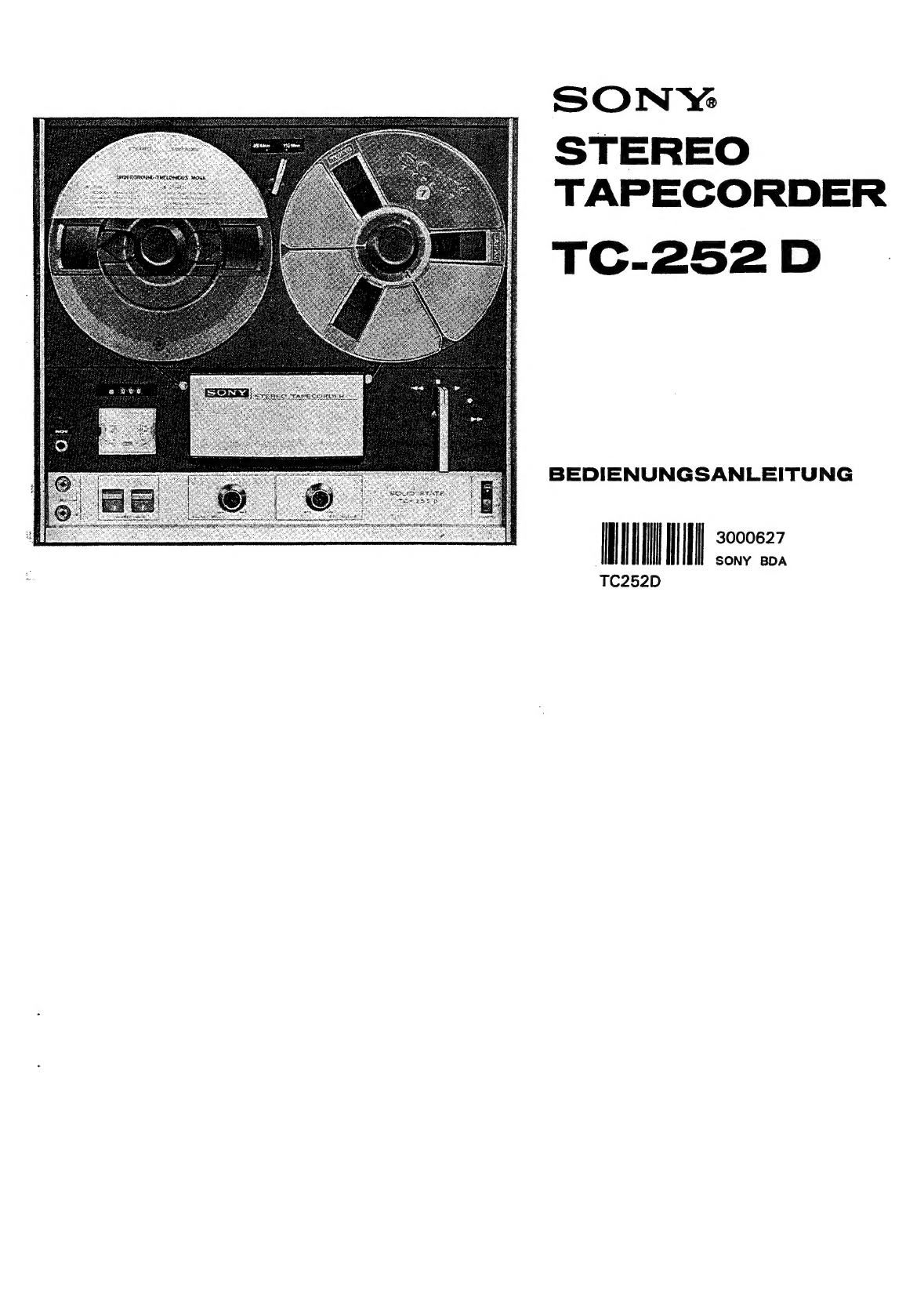
Le
Modéle
SONY
TC-252D
est
un
plateau
magnétophone
stéréo/
mono
a
quatre
pistes
pour
enregistrement
et
reproduction
précis
de
la
bande
en
conjonction
avec
des
composants
de
haute
fidélité.
Le
Modéle
TC-252D
remplira
toutes
les
demandes
requises
par
les
enthousiastes
de
haute
fidélité.
Les
caractéristiques
particuligres
sont:
moteur
sans
vibration,
circuit
entiérement
transistorisé
au
silisium
pour
abaisser
les
bruits
et
la
distorsion
&
un
degré
exceptionnel,
la
tension
de
polarisation
profesionnelle
4
haute
fréquence,
filtre
grattoir
de
scientillement
qui
élimine
ies
distorsions
de
la
bande
en
modu-
lation,
commutateur
de
coupure
automatique,
prise
de
casque
_d’écoute
stéréo
et
roulette
d’entrainement
rétractile.
Le
TC-252D
qui
vous
arrive
en
coffret
noyer
attrayant
peut
étre
utilisé
en
position
horizontale
ou
en
position
verticale.
Le
montage
individuel
4
votre
systéme
stéréo
est
aussi
possible.
PREAVIS
SUR.
LE
VOLTAGE
ET
LA
FREQUENCE
Le
Modéle
SONY
TC-252D
a
deux
types.
1.
Pour
l'utilisation
aux
Etats-Unis
et
au
Canada
En
conformité
des
normes
de
UL
et
de
CSA,
le
voltage
du
magnétophone
est
mis
a
fonctionner
sur
117
volts,
courant
alternatif,
60
Hz
(périodes).
.
2.
Pour
l'utilisation
dans
les
autres
pays
Le
magnétophone
peut
étre
ajusté
pour
fonctionner
sur
courant
alternatif
de
soit
100, 110,
117, 125,
220
ou
240
volts
de
courant
alternatif,
50
ou
60
Hz.
Avant
de
le
brancher
sur
courant
domestique,
s'assurer
que
votre
magnétophone
a
bien
été
réglé
a
la
tension
et
la
fréquence
de
courant
de
votre
secteur.
Pour
les
détails,
voir
‘‘Adaptation
au
courant
du
secteur’
page
13.
TABLE
DES
MATIERES
Emplacement
des
réglageS
...........ccssscccecsesecesseseeccseseeeeseees
2
NOTCS
yo
Bret
ie
ocaciistetiok
wukatet
coats
ds
deadetastevnterslescbecualsctdetetetes
3
Connexion
a
un
préamplificateur/amplificateur
..................
3
Ecoute
€rn
stér€0
oo...
cccecccccccssaceessescceceuessececeeeeeceseeeseceseses
5
ECOuUte
OM
MOMO........
cece
cccssessssessesssessanecceceeesereeeenesesessanacvense
5
Systéme
des
raccords
.............
5
Enregistrement
en
stéréo
7
Enregistrement
en
mono
7
Enregistrement
SON-SUC-SOM
........cccsccccccesssseccuccccecereceeeeceeers
9
Effacement
de
la
bande
Collage
de
{a
bande................
EMtreten
reac
cbrstsaviatecet
cere
eveestasets
causcunb
coer
ons
ortdes
se
ah
Suede
Montage
individuel
...........cccccccccccccsssesececceessseseasenesccaceeseeees
Adaptation
au
Courant
du
Se@Cteur
oo...
ee
cceeeeeeeeceneeeeeeeeea
13
Sp€cifications
techniques
..........ccccccsesseessesescseteecsesssseessers
15
Diagramme
schématique
............c:ccccccsssecseecesssesecceesecssccsess
16
Das
SONY
Modell
TC-252D
ist
ein
Vierspuren-Stereo-/Mono-
Tonbandgerat
sowohl
fiir
Aufnahme
als
auch
zur
Wiedergabe
aufgenommener
bzw.
gespielter
Tonbander
mit
Hi-Fi-Bestand-
teilen
und
-Lautsprechern.
Das
252D
befriedigt
alle
Bedirfnisse
der
Hi-Fi-Enthusiasten
nach
héchster
Tontreue
bei
Aufnahme
und
Wiedergabe.
Besondere
Eigenschaften
sind:
Vibrationsfreier
Motor;
ganz
mit
Silizium-Transistoren
bestiickte
Schaltung
mit
auBergewohnlich
wenig
Nebengeraduschen
und
minimaler
Verzerrung;
&uBerste
Hochfrequenz-Vormagnetisierung
;
Kratzfilter
der
unerwiinschte
Modulationsverzerrung
des
Tonbandes
verhindert;
automatische
Laufwerkabschaltung;
Stereo-Kopfhéreranschlu8;
zuriickziehbare
Andruckwalze.
Das
252D
ist
in
einem
ansprechenden,
nuSbaumfurnierten
Gehduse
untergebracht
und
kann
in
senkrechter
oder
waage-
rechter
Lage
betrieben
werden.
Es
kann
in
verschiedene
Klanganlagen
passend
eingebaut
werden.
BETRIEBSVOLTAGEN
UND
-FREQUENZEN
Das
SONY
Modell
TC-252D
gibt
es
in
zwei
Ausfiihrungen:
1.
Fir
die
USA
und
Kanada
GemaB
den
Sicherheitsbestimmungen
der
UL
und
CSA
ist
das
Gerat
fiir
den
Betrieb
mit
117V,
60
Hz
Wechselstrom
eingestellt.
2.
Fir
andere
Lander
Das
Gerat
ist
auf
100V,
110V, 117V, 125V,
220V
und
240V,
und
auf
50
oder
60
Hz
einstellbar.
Vor
Inbetrieb-
nahme
des
Gerats
versichere
man
sich,
da8
Betriebsvoltage
und
-Frequenz
des
Geradts
mit
dem
lokalen
Netz
iiberein-
stimmen.
Weitere
Anweisungen
finden
Sie
unter
der
Uberschrift
‘‘Anpassen
an
das
G6rtliche
Stromnetz’’
auf
Seite
13.
INHALTSVERZEICHNIS
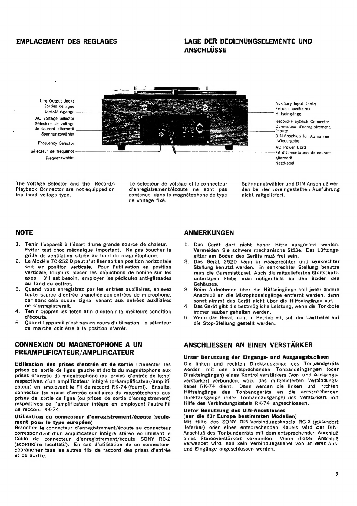
Lage
der
Bedienungselemente
und
Anschliisse
ANMerkungZen
..........cceecesseecesssecceeesseeeesseesanecsecenes
AnschlieBen
an
einen
Verst€rker..............
Stereo-Wiedergabe
..............cccescceseeeeeeeeeees
Mono-Wiedergabe
................ccccseeeeeseeeeeees
ANSCHIUSSO:
cio
ivs
se
edc
sans
sossseendeciesessianees
Stereo-Aufnahme
oo...
ceecceeeceeeenee
scene
Mono-Aufnanme
......
cee
cecccecceccseceeeecnesees
Multiplay-Aufnahme
...............08
Ldschen
des
Tonbandes.............
Kieben
des
Tonbandes
............
Instandhaltung
.........
eee
eee eee
Einbau
in
eine
Heimanlage
Anpassen
an
das
6rtliche
Stromnetz
Technische
Daten
..............ccccccsececessceeeeceees
SChalt
plan
is0:
scciesacdssesvasaees
avssavecssbeveddevsees


 User manual")