GE Multilin EPM 2000 Series User manual

EPM 2000
Power Metering System
INSTRUCTION MANUAL
Manual P/N: 1601-0156-A2
Manual Order Code: GEK-106556A
Copyright © 2005 GE Multilin
GE Multilin
215 Anderson Avenue, Markham, Ontario
Canada L6E 1B3
Tel: (905) 294-6222 Fax: (905) 201-2098
Internet: http://www.GEmultilin.com
g
GE Industrial Systems

Customer Service and Support
Customer service and support is available 24 hours a day, 7 days a week. Please have the
model, serial number and a detailed problem description available. If the problem concerns a
particular reading, please have all meter readings and settings available.
For customer or technical assistance, call: 1-888-GE4SERVICE (1-888-434-7378)
Product Warranty
GE warrants all products to be free from defects in material, workmanship and title and will
be of the kind and quality specified in GE’s written description in the manual. The foregoing
shall apply only to failures to meet said warranties, which appear within one year from the
date of shipping. During the warranty period, GE will, at its option, either repair or replace
any product that proves to be defective.
Limitation of Warranty
This warranty does not apply to defects resulting from unauthorized modification, misuse or
use for any reason other than electrical power monitoring.
OUR PRODUCTS ARE NOT TO BE USED FOR PRIMARY OVER-CURRENT
PROTECTION. ANY PROTECTION FEATURE IN OUR PRODUCTS IS TO BE
USED FOR ALARM OR SECONDARY PROTECTION ONLY.
THIS WARRANTY IS IN LIEU OF ALL OTHER WARRANTIES, EXPRESSED OR
IMPLIED, INCLUDING ANY IMPLIED WARRANTY OF MERCHANABILITY OR
FITNESS FOR A PARTICULAR PURPOSE. ENERCON SHALL NOT BE LIABLE
FOR ANY PENAL, INDIRECT, SPECIAL OR CONSEQUENTIAL DAMAGES
ARISING FROM ANY AUTHORIZED OR UNAUTHORIZED USE OF ANY
ENERCON PRODUCT. LIABILITY SHALL BE LIMITED TO THE ORIGINAL
COST OF THE PRODUCT SOLD.
Statement of Calibration
Our instruments are inspected and tested in accordance with specifications published by an
independent testing facility. The accuracy and calibration of our instruments are traceable to
the National Institute of Standards and Technology through equipment that is calibrated at
planned intervals by comparison to certified standards.
Disclaimer
The information presented in this publication has been carefully checked for reliability;
however, no responsibility is assumed for inaccuracies. The information contained in this
document is subject to change without notice.

GE Multilin Sub Meters
CONTENTS
1. OVERVIEW 6
1.1. Physical Description 7
1.2. Front Panel 7
1.2.1. The Indicators 8
1.2.2. The Keys 9
1.2.2.1. Keys Example 11
1.3. EPM 2000 Technical Specs 11
1.3.1. Main Features 11
1.3.2. Standard Measurements 12
1.1.1.1. Accuracy 12
1.3.3. Auxiliary (Control) Power Supply 13
1.3.4. Front Panel Display 13
1.3.5. Dimensions & Shipping 13
1.3.6. Environmental Conditions 13
1.3.7. Installation & Input Ratings 13
1.3.8. Safety Construction 14
2. QUICK START GUIDE 15
2.1. Keypad Operation 15
2.1.1. Auto-Scroll 18
2.1.2. TURBO key 19
2.2. Setup (Program) 20
2.2.1. Editing the Setup 21
2.2.2. Notes on the Energy Integrator 26
2.2.2.1. Integrator Overflow 26
2.3. Summary 27
3. AC POWER MEASUREMENT 28
3.1. Three-Phase Systems 28
3.2. Consumption & Poor PF 29
3.3. “3D” kVA Measurement 29
4. MECHANICAL INSTALLATION 30
4.1. Installation Process 33
4.1.1. Panel Mounting for New Installations 33
4.1.2. Location 33
4.1.2.1. Usage 33
4.1.2.2. Panel Considerations and Environment 33
4.1.2.3. Viewing 34
4.1.3. Mounting 34
5. ELECTRICAL INSTALLATION 35
5.1. Auxiliary (Control) Power Supply 36
5.2. Potential Transformers and Current Transformers 36
5.2.1. PT, CT Wiring Considerations 36
5.3. Voltage Signal Connections 37
5.3.1. PT Connections 37
5.3.2. Selecting the Voltage Fuses 37
5.4. Current Signal Connections 37
5.4.1. CT Connections 38
5.4.2. CT Polarity 38
5.4.2.1. CT Connection Reversal 39
5.5. Setup – System Type 39
5.6. Phase Labels 39

GE Multilin Sub Meters
5.7. Connection Diagrams 39
5.7.1. EPM 2000 Rear Panel 40
5.7.2. Three Phase 3 Wire Delta 41
5.7.3. Three Phase 4 Wire Star (Wye) 42
6. COMMUNICATION INSTALLATION 43
6.1. RS-485 43
6.2. Repeaters 45
6.3. Factory Settings 46
6.4. Modbus Registers 46
6.5. Register Map 47
6.5.1. RMS Total/Average Block 47
6.5.2. RMS Phase A Block 47
6.5.3. RMS Phase B Block 48
6.5.4. 48
6.5.5. RMS Phase C Block 48
6.5.6. Forward Integrator Block 49
6.5.7. 50
6.5.8. Favorite Block 50
6.5.9. 51
6.5.10. Display-Only Parameters 52

GE Multilin Sub Meters
1. OVERVIEW
The EPM 2000 Digital Power Meters offer comprehensive Three-Phase Electrical
Instrumentation and load management facilities in a compact and rugged package.
To get the best out of your investment, we suggest that you take a few moments to review this
Manual. This Chapter contains the main operating instructions. The remaining Chapters explain
the Installation and Setup steps before the Meter is ready for use.
The EPM 2000 is a universal meter. Before use, please program the SYS (measurement system
configuration), PT and CT ratios through the front panel keys. Otherwise, it will read your system
incorrectly.
GE stands behind your EPM 2000 products with complete User Support and Service. If the need
arises, please do not hesitate to contact us at 1-888-GE4SERVICE (1-888-434-7378).
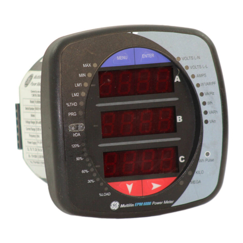
Figure 1-1. The EPM 2000 Digital Power Meter.

GE Multilin Sub Meters
1.1. Physical Description
FRONT: The front panel has 3 rows of 4 digits / characters each, with auto scaling “K” kilo, “M”
Mega and “-” negative indications. The “kilo” and “Mega” indications lit together show Giga
readings. Load bar graph on right side of the display gives the indication of consumption in terms
of the %Average load. Five smart-keys make navigating the parameter set very quick and
intuitive for viewing data and configuring (Setup) the EPM 2000.
REAR: The voltage and current terminals and the communication port are located on the back of
the meter.
1.2. Front Panel
The front panel contains the following indicators and controls:
• Three rows of Numeric displays, 4 digits each that display three RMS parameters
simultaneously, or one Energy Parameter. The displayed readings update every second.
• For each row: Kilo, Mega (Kilo + Mega = Giga) indicator and a Negative(-) indicator.
• Load bar graph gives the indication of consumption in terms of the %Aavg of load.
• Five keys to scroll through the display pages.
The EPM 2000 products solves the problem of cluttered indicators by prominently displaying the
parameter name right on the large, numeric readouts. For the first time in a Panel Meter, the
Parameter Name is as clearly readable as the value. The name is displayed every 9
th
second for
2seconds(8+2), as well as each time you press a key. This also allows programmable Phase
Labels in the EPM 2000 products. You can choose from 123 (Factory setting), Abc, ryb, pqr, or
rst.
At this point you can scroll to the next page you want to see. If you’re not sure which page
you’re watching, one press of any key will immediately identify the Name of the Parameter
being displayed. The second key press takes you to the next page.
Figure 1-2: The EPM 2000 front panel with display and keypad

GE Multilin Sub Meters
1.2.1. The Indicators
Table 1-1-: Kilo, Mega and Negative Indicators
M
Mega: When lit, indicates that the reading is in Mega, (10^6). 10,000K is shown as
10.00M. 1.0 M is displayed as 1000K.
When Kilo and Mega are both glowing, the reading is in Giga (10^9). 10,000M is
shown as 10.00G. 1.0G is shown as 1000M.
Neg: -When lit, indicates that the reading is negative Per IEEE 100 and industry
standard practice by meter men, the following are Negative:
• With Forward Flow of Watts: Capacitive (Leading) VARs & PF.
• With Reverse Flow of Watts: Inductive (Lagging) VARs & PF and Watts.
K Kilo: When lit, indicates that the reading is in Kilo (10^3). 10,000 is shown as
10.00K. 1.0K is shown as 1000.
Table 1-3: Giga, Mega (M), Kilo (K) & Decimal Point Scaling
RMS Reading Indicator
Less than 0.001 K, M Off, displays “0.000”
Less then 9999 K, M indicators Off
Above 9999 K ON
Above 9999 k M ON
Above 9999 M Giga (K + M indicators ON)
Upto 9999G Giga
Above 9999G Display shows “Hi” for +ve numbers and “Lo” for –ve numbers
RMS readings are 4 digits. Energy readings have eight digits, including four additional fractional
digits. The maximum number the Meter handles is 9,999 G for RMS and Energy values.
This means that the Energy readings of the meter will overflow between approximately 2 months
to 3 years depending upon the PT and CT ratios programmed. See Table 2.6 “Integrator Overflow
Period”

GE Multilin Sub Meters
1.2.2. The Keys
Operating the meter is easy using the five keys to take navigate through the Keypad Operations
Table. The Display Pages “expand” as you go right, much like the directory or Explorer “tree”
displayed on any computer. The display shows where you’re headed.
Table 1-5: The Keys
Right Key:
• Go forward into sub-parameter pages.
• During Edit Setup values, select next (right side) digit.
Left Key:
• The Opposite of the Right key.
• Go Back towards the Main Parameter Pages. Going Left past “Prog” requires Code
entry to enter Main Menu (Setup and Clear)
• During Edit Setup, selects previous (left side) digit
• Exits from Edit mode, back to the Main Menu.
Up Key:
• Scroll Up thru other Display Pages at the same level.
• Continuous pressing for 3 seconds initiates limited Auto-scroll (within the same
group of pages). Press any key to return to Manual scrolling.
• Increases the value of the blinking digit during Edit. Typically while changing the
Meter Setup settings.
Down Key:
• The Opposite of the Up key.
• Scroll Down thru other Display Pages at the same level, thru all functions.
• Continuous pressing for 3 seconds initiates the Full Auto-scroll mode, thru all
functions. Press any key to return to Manual scrolling.
• Decreases the value of the blinking digit during Edit.
TURBO Key:
• The TURBO key scrolls thru the following pages: RMS (Home page),
VLL, A,PF VLN,A,F VA, W, VAR W,VAR, PF PF1, PF2,PF3 , VAh and
Wh. This gives simple one-touch access to the most commonly used parameters,
even for unskilled operators. “One Touch” does not operate in the Setup (Program)
Mode.
• If you’re lost, the TURBO key is a quick way to get back to the RMS home
page.
• Continuous pressing for 3 seconds initiates Auto-scrolling through the above
Favorite pages.
The parameter name is displayed every 9
th
second for 2seconds, as well as the first time you press
a key.
At this point you can scroll to the next page you want to see. If you’re not sure which page
you’re watching, one press of any key will immediately identify the Name. The second key
press takes you to the next page.
The Meter Menus and Displays are organized as below. Navigating with the EPM 2000 is very
easy and intuitive. For full details, see the Keypad Operations Table. The left-most column
(RUN, CLR, SET) constitutes the “Main Menu”. Press the key in the direction you want to go.
Display shows where you’re headed.
GE Multilin Sub Meters
Table 1-6: Menu and Display Map.
Press the key that takes you in the desired direction. You can’t cross the thick boundary.
Run Prog
RMS V, A, PF V1, V2, V3
A1, A2, A3
Integ VAh
Wh
Clr
Set V pri
A pri
Main
Menu

GE Multilin Sub Meters
11
1.2.2.1. Keys Example
Here’s an example to try:
When you switch on a factory fresh meter, it starts at the “RMS” page, circled “1” in the
diagram below. This will be our “Home Page”.
From here, to now go to the VAh Energy Page, circled “3” in the diagram below:
1. Start at “RMS”
2. Go Down to “Integ” and
3. Go Right to “VAh”
There are no complicated key sequences, since the grouping of parameters is intuitive. And
the keys always do what they say, under all modes.
A complete Keypad Operations Map appears in the next chapter. “RUN” constitutes the
Main Menu, along with “Clear” and “Set”, not shown above, but evident in the left-most
“Main Menu” (“RUN”, “CLR”, “SET”) column. Getting into the Main Menu requires you to
first enter a code.
1.3. EPM 2000 Technical Specs
• The EPM 2000 is a high-accuracy, low cost, ultra-compact, power and energy meter that
offers ISO 9000 quality, accuracy, functional flexibility and MODBUS RTU
communications capability. The standard unit flush-mounts in a DIN 96 cutout. Conforms
to UL and CE safety requirements.
• The EPM 2000 is designed for retrofit application such as replacement of existing analog
meters and is also usable as a stand-alone meter in custom panels, PDUs, switchboards,
switchgear, UPS’s, generator sets, MCCs systems etc.
• The EPM 2000 provides easy communication to PLCs, DCS, BMS and other systems
through the use of Modbus RTU communications on RS 485, isolated to 2kV for 1
minute, from other circuits.
• The EPM 2000 Series of products are configurable & programmable through the front
panel.
1.3.1. Main Features
The EPM 2000 Series supports the following features:
• Measures true RMS electrical parameters. 1 Second updation.
• IEC 61036 class 1.0 accuracy.
• Provides surge Impulse withstand to IEEE C37.90.1 Surge: 6kV IEC 60060 1.2µS/50µS.
• Fast Transient: >4kV IEC 61000-4-4 Level 4, ESD IEC 61000-4-2, Emission meets
CISPR 22
• Power 4 Quadrant, Energy 2 Quadrant. Provides 3D power computation for kVA
• load bar graph for the quick estimation of consumption from a distance without touching
any keys.
• Customized new display for easy readability.

GE Multilin Sub Meters
12
1.3.2. Standard Measurements
The EPM 2000 can measure, locally display and remotely transfer over MODBUS RTU, the
following electrical parameters over the input range with an accuracy of 0.5% or better for
Volts and Amps and 1% for Power and Energy functions:
Amps: 50mA – 6A, Overload: 10A continuous, 50A for 3 seconds.
Volts: 80- 600V Phase - Phase and 48 - 347 V Phase – Neutral
Burden (Load): 0.2VA per Volts / Amps input
Frequency: 45 – 65 Hz
• True RMS voltage phase to neutral and 3phase average.
• True RMS voltage phase to phase and 3phase average.
• True RMS current per phase and 3phase average.
• Real Power and Energy.
• Reactive Power and Energy.
• Apparent Power and Energy.
• Power Factor.
• Frequency.
The EPM 2000 provides all single phase (per-phase) Real, Apparent, Reactive Power and
Power Factor values. Positive (Inductive) and Negative (Capacitive) Reactive Energy is
separately accumulated for Lead / Lag analysis.
1.3.3. Accuracy
Measurement Class 1.0, % of reading
• Voltage LN, per phase 0.5
• Voltage LL, per phase 0.5
• Voltage LN, avg 0.5
• Voltage LL, avg 0.5
• Amp, per phase 0.5
• Amp, avg 0.5
• Amp, Phase Angle per phase 2º
• Frequency 0.1
• Real Power, (kW) Per Phase & Total 1.0
• Reactive Power, (kVAR) Per Phase &
Total 2.0
• Apparent Power, (kVA) Per Phase &
Total 1.0
• Power factor, Per Phase & average 1.0
• Active Energy, (kWh) Import/Export 1.0
• Reactive Energy, (kVARh) (Ind / Cap) 2.0
• Apparent Energy, (kVAh) 1.0
* Additional error of 0.05 % of full scale for meter input current below 100 mA.

GE Multilin Sub Meters
13
1.3.4. Auxiliary (Control) Power Supply
The meter needs a single phase AC or DC supply to power its internal electronics.
• ac 80v – 270v, 45 – 65 Hz
• dc 80v – 270v
• Burden (load) 3VA
1.3.5. Front Panel Display
• Brilliant 3 lines 4 digit (digit height 14.2 mm) per line, LED display with auto scaling
capability for Kilo, Mega, Giga.
• The display provides the user access to all phase Voltages (phase to neutral and phase to
phase), Currents (per phase and total), Watts, VARs, VA, Power Factor, Frequency and
kWh, kVAh and kVARh.
• The EPM 2000 displays total volts, amps and frequency simultaneously.
• Load bar graph for the indication of the consumption in terms of %Avg.
• Easy setup for common configuration parameters through keys located on the faceplate.
• Password protection on setup parameters
1.3.6. Dimensions & Shipping
• Basic unit installed depth 80 mm behind bezel with 90x90 mm panel cutout, flush mount.
The Protection cover affixed over the rear Terminal Block extends the depth to 82 mm.
• Bezel dimension 96 x 96 mm,. Panel Cutout 91 x 91 mm
• Weight 400 grams approx Unpacked 500 grams approx Shipping
1.3.7. Environmental Conditions
• Sealed dust-proof construction. Meets IP51 for the front panel
• Temperature Operating: – 10 to 60° C, 14
o
F to 140
o
F
Storage : – 25 to 70°C, -13
o
F to 158
o
F
• Humidity: Below 5% to 95%, non-condensing
1.3.8. Installation & Input Ratings
• Auto-ranging voltage inputs allow direct connection up to 347 VLN/600 VLL AC
systems (no PTs required up to 600 VLL phase to phase).
• Supports (field configurable) direct 4-Wire Star (Wye), 3-Wire Star (Wye), 3- Wire Delta
configurations and single phase via Star (Wye) Phase 1.
• 3-phase voltage and current inputs
o Volts: 48 – 347 VLN Phase–Neutral, 80 – 600 VLL Phase-Phase,
Overload – Continuous 600 VLL with full accuracy, 750 VLL MaxHz.
50 / 60 ,
o Amps: 50mA – 6A, Overload: 10 A continuous, 50A for 3 seconds
o Field configurable for 5 Amp or 1 amp secondary CTs
o Burden (Load): Less than 0.2VA per Volts / Amps input
o Frequency: 50 / 60Hz 45 – 65 Hz

GE Multilin Sub Meters
14
1.3.9. Safety Construction
•
Self extinguishable V0 plastic, double insulation at accessible area.
•
Pollution Degree II
•
Measurements Category III
See Chapter 4: Mechanical Installation.


GE Multilin Sub Meters
15
2. QUICK START GUIDE
This Chapter shows at a glance, how to view the following pages:
•
Viewing Three-Phase Total values
•
Viewing Per-phase Values
•
Viewing Energy Values (Intg)
•
Viewing the % of average load bar graph
•
Clearing (Resetting) Energy Values
•
Setting-up (Program) the meter before use.
The EPM 2000 displays:
• Voltage:
Three voltage measurements Line-to-Line: 1-2, 2-3, 3-1 and one Average,
Three voltage measurements Line-to-Neutral: 1-4, 2-4,3-4 and one Average.
• Current:
Three current measurements phase-wise: A, B, C, one average current of all three phases and three
current phase angles A
oA
, A
oB
, A
oC
w.r.t. the corresponding Voltage Line-Neutral vector.
• Frequency:
Measured from whichever phase is active.
• Power: VA, W, VAR, PF. Per phase and Total. Per-Phase W readings provide a quick CT
Polarity Check. A negated W phase reading indicates CT reversal.
• Energy:
VAh, Wh, +VARh (Ind), -VARh (Cap), Run Hrs, On Hrs, Supply Interruptions (outages)
• % average Load Bar graph:
Load Bar graph indicates consumption in terms of %Aavg. Now user can quickly estimate the
load by viewing the display without operating any keys. The bar graphs consists of 12 segments.
Each segments indicates 10% of average load.
• Kilo, Mega, Giga indication for the above parameters.
2.1. Keypad Operation
The Table below is quite simple to use. Look at the shaded left half, under the parameter
“Name”: Follow these simple steps.
• First take a quick look at what the Keys do. Try the simple example.
• Now, try getting around to other parameters, by moving Up, Down, Right and Left. For
viewing readings in different display pages you will normally be within (to the right of)
the “RMS” and “INTG”.
o You cannot go Down or Up through the thick horizontal lines- you must navigate
Left, around them
o The “Kilo”, “Mega” and “Negative” Indicators are automatic. “Kilo” and “Mega”
light up together to show “Giga”.
• To go Left into the Main Menu (“RUN”) enter Code- See Table 2.1 Note 1
• Once in the Main Menu (“RUN”), you can go Down to “CLR” or “SET”. You can then
clear the integrator or Setup Meter Settings by going right. When done, go left back to the
Main menu, go Up to Run then go Right in to RMS to view the Display Pages again.
Figure 2-1: The Run Mode Flow chart

GE Multilin Sub Meters
16
Legend
Use or keys
Use or
keys
Use key only
Run
V Ln
A
F
PROG
RMS
VA
W
VAR
W
VAR
PF
VAh
Wh
VARh
-
VARh
run.h
V LL
A
PF
A
°
1
2
3
V 12
23
31
V 1
2
3
A 1
2
3
W 1
2
3
VAR. 1
2
3
PF 1
2
3
VA 1
2
3
Intg
On.h
Intr
diAG
2000
03.01
01.00
1.00
9600
Evn 1
RS
-
485
status
Factory
QA only

GE Multilin Sub Meters
17
Table 2-1: Meter Function Map
Code
Note 1.
N
ame
Description
Run
Prog
RmS
Start
Here
V LL
A
PF
V 12
23
31
V LL =
A =
PF =
Voltage,Line to Line,Average. V 12 = Voltage, RMS Phase 1 to Phase 2
Current, Average. 23 = Voltage, RMS phase 2 to phase 3
Power factor, Average 31 = Voltage, RMS phase 3 to phase 1
V 1
2
3
V 1 =
2 =
3 =
Voltage, RMS phase 1 to Neutral
Voltage, RMS phase 2 to Neutral
Voltage, RMS phase 3 to Neutral
V Ln
A
F
A 1
2
3
V Ln =
A =
F =
Voltage, Line to Neutral, Average. A 1 = Current, RMS phase 1
Current, phase wise, Average. 2 = Current, RMS phase 2
Frequency in Hertz. 3 = Current, RMS phase 3
A
O
1
2
3
A
O
1 =
2 =
3 =
Current, Phase Angle of phase 1 in degrees.
Current, Phase Angle of phase 2 in degrees.
Current, Phase Angle of phase 3 in degrees.
VA
W
VAR.
VA 1
2
3
VA =
W =
VAr =
Volt-amperes, Total. VA 1 = Volt-amperes, phase 1
Watt, Total 2 = Volt-amperes, phase 2
VAr, Total. 3 = Volt-amperes, phase 3
W 1
2
3
W =
VAr =
PF =
Watt, Total. W 1 = Watts, phase 1
VAr, Total.
Note :
"-" Watts = reverse current. 2 = Watts, phase 2
Power factor, Average 3 = Watts, phase 3
VA
W
PF
PF 1
2
3
PF 1 =
2
=
3 =
Power factor, phase 1.
Power factor, phase 2.
Note
: "-" Indicates Lead (Capacitive) Power factor.
Power factor, phase 3.
VAr.
1
2
3
Var.1=
2=
3=
VAr, phase 1.
VAr, phase 2. Note: “-
” Indicates Lead (Capacitive) VAr.
VAr, phase 3.
Intg VA.h
VA.h = Volt-ampere-hours.
All integrators clear automatically at 9999 Giga value of any Integrator.
W.h
W.h = Watt-hours. If watts is negative, VA.h, W.h,VAr.h, -VAr.h do not Integrate.
VAR.h
VARh =
VAr-hours, Inductive.
-VARh
-VARh=
Negative VAr-hours, Capacitive.
run.h
run.h = Run hours. Total hours the Load was On. Accumulates when current is present.
On.h On.h =
ON hours. Total hours the meter was ON. Accumulates if auxiliary supply is present
(irrespective of input signals).
Intr Intr =
Auxiliary interruption. Accumulates the auxiliary interrupt.
M
a
i
n
M
e
n
u

GE Multilin Sub Meters
18
Code
Note 1.
N
ame
Description
Clr Intg Intg
y / n t
o
Clear
Clr = Clear. If "y", Clears all integrator parameters (above) to zero.
Set
Save
y / n
2000
03.01.
01.00
SYS
V.PRI
V.SEC
A.PRI
A.SEC
LAbL
VA.Fn
baud
Prty
Id
2000
03.01.
01.00
StAR
415.0
415.0
100.0
5.000
123
3d
9600
EVn.1
1.000
to Edit
Setting
Model = 2000. non editable.
Version = 03.01.01. non editable.
SYS = Power system's configuration* : Star (3E 4V3A), Delta (3E 3V2A)
V.PRI = Voltage primary winding(PT) * : Line to Line: 100V to 999kV(415.0)
V.SEC = Voltage secondary winding(PT)* : Line to Line : 50V to 601V (415.0)
A.PRI = Current primary winding.(CT)* : 1A to 99kA (0100)
A.SEC = Current secondary winding.(CT)* : 1A to 6.5A. (5.000)
LAbL = Phase labeling formats. : 123, ryb, rst, Pqr, Abc.
VA.Fn = VA function selection : 3d, Arth
baud = Baud rate : 1200, 2400, 4800, 9600, 19200.
Prty = Parity and Stop bit settings : EVn.1, EVn.2, Odd.1, Odd.2, no.1, no.2
Id = RS485 Device ID number : 001 to 247. (Evn.1 = Even. 1 stop bit)
*changing these values while the device in use, is not recommended
dIAG Id
baud
Prty
1.000
9600
Evn.1
For factory testing only
dIA2
Mdl
Ver
Ver
2000
03.01.
01.00
For factory testing only
NOTES:
1. To “Clear” Integrated values or “Set” meter settings, you must first enter the Main Menu.
• Go Left to the “RUN” page from "PROG".
• You must now enter the Factory Set code of 1000, to proceed.
o "Code y”, followed by the entry of the Code “1000" is required.
o To enter the code, edit the blinking digit value Up or Down to get “1000”.
o Keep going Left.
o Without entering the code, you may view the settings, but you can’t change
them.
2. Within the “SET” page options, the Factory settings are shown Bold Text in the right side
column above.
2.1.1. Auto-Scroll
Auto-Scroll allows you to monitor a group of Display Pages sequentially, every 5 seconds,
without constant key pressing. This is convenient for viewing from a distance. Since the EPM
2000 displays the Parameter Name(1sec) followed by the Value(4 sec) on the same large
displays, both are equally readable from a distance. No more squinting at a clutter of
parameter indicators.
To enter auto-scroll, go to the desired display page and keep the Up or Downkey
pressed for minimum 3 seconds. The display flashes “Auto” and then automatically scrolls
through other pages at the same level (column in the above table). Press any key to revert to
Manual Scrolling.
• The Up key enters Limited Auto-scroll – within the same Group, eg only “RMS” or
only “INTEG”.
• The Down key enters Full Auto-scroll- down the entire column of pages.

GE Multilin Sub Meters
19
2.1.2. TURBO key
• The TURBO key
↵
↵↵
↵
scrolls thru the following pages:
RMS, VLL,A,PF VLN,A,F
VA,W,VAR W,VAR,PF PF1,PF2,PF3 VAh Wh
. This gives simple one-touch access to
the most commonly used parameters, even for unskilled operators. “One-touch” does not
operate in the Setup (Program) Mode. Optional parameters are in blue color.
• If you’re lost, the TURBO key is a quick way to get back to the RMS home page.
• Continuous pressing for 3 seconds initiates Auto-scrolling through the above Fav pages.

GE Multilin Sub Meters
20
2.2. Setup (Program)
The Meter must be Set (programmed/configured) to match the application settings, before
use. Otherwise, the readings will be wrong. All the Setup values can be re-programmed at any
time, upon entering “SET” However, the settings: Sys (Star/wye or Delta), Vpri, Vsec, Apri,
Asec critically determine the scaling of measured readings. While the scaling may be used to
tune out Instrument Transformer errors, wrong settings will upset the readings of running
systems. It is the user’s responsibility to ensure that only qualified personnel correctly Set-up
the Meter.
Action Display
Remarks
From the “RMS” or “INTG”
page, go Up
Then go Left.
"Code y" is displayed. “y"
blinks.
Prog
"Code y "
The meter is about to enter the Main Menu. “y" blinks.
To proceed with Code Entry, we need to enter the Main
Menu.
• Go Left .
Or, to abort and re-enter RMS:
• Press .
Or, to only view setup, (no edit):
• Press or to toggle “y” to “n".
• Press to enter Main Menu.
• "Fail" is flashed, then "run" is displayed.
To proceed with Code Entry: "000 0" The blinking digit indicates the cursor.
The code is Factory Set to
1000. Press to enter each
digit. Three times totally.
"2000" We have now entered the Units, Tens and Hundreds digits.
The Thousands digit needs to be changed from 2 to 1.
Press to decrement “2". " 1 000"
Now the Code of 1000 is almost in.
Press to enter the Main
Menu. "0000"
“Pass”
“run”
Or,
“Fail”
Notice that a “0” quickly hides each code
-digit you enter.
“run” indicates a successful entry into the Main Menu.
Congratulations!
If you were not successful, don’t despair; you can have
another go from the top of this Table! Briefly switching off
the Meter will easily return you to the RMS page, the starting
point.
Now press
Again press “CLR”
“SET”
You are at the Setup page.
Press to get into “SET” “2000” You’ve now entered the Setup Menu. The first two entries are
the Model Number and firmware version for easy
identification.
Go to see other Settings.
Go to see and change their values.
Once you’re done, re-trace
your path: and .
Remember “Save Y”
“run” You’re now back to the top of the Main Menu. Go . You’ll
see RMS. You can now go or to view all the display
pages.
Table of contents
Other GE Measuring Instrument manuals