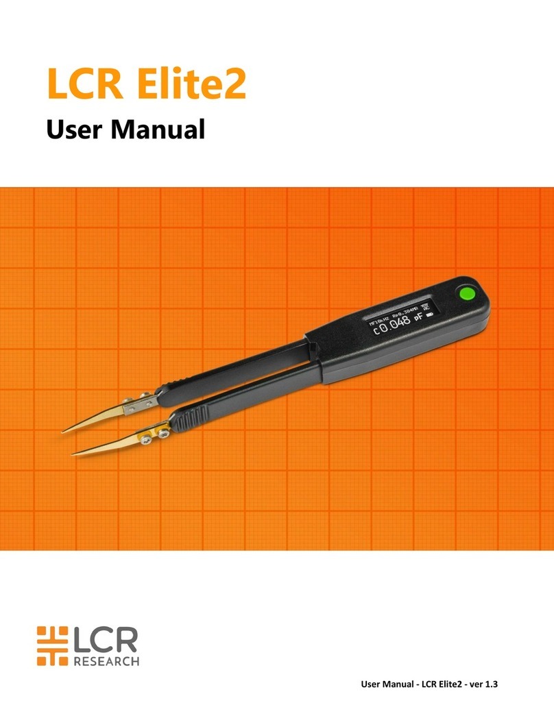
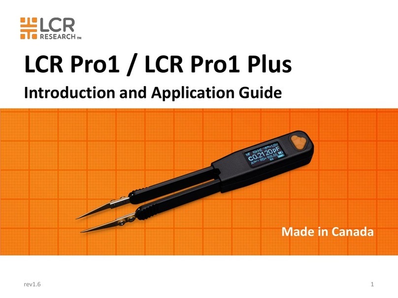
LCR Pro1 User manual

User Manual - LCR Pro1/Pro1 Plus - ver 1.06
LCR Pro1/Pro1 Plus
User Manual

User Manual - LCR Pro1/Pro1 Plus - ver 1.06
Notices
The information contained in this document is provided “as is,” and is subject to change, without notice,
in future editions.
This document contains proprietary information that is protected by copyright. All rights are reserved. No
part of this document may be photocopied, reproduced, or translated to another language without the
prior agreement and written consent from LCR Research Ltd.
© LCR Research Ltd. 2016
Warranty
LCR Research warrants this product to be free from defects in materials and workmanship for a period of
one (1) year from the shipment date. LCR Research warrants the following items for ninety (90) days from
the date of shipment: rechargeable batteries, gold plated tips and documentation. During the warranty
period, LCR Research will, at its option, either repair or replace products that prove to be defective. For
warranty service or repair, this product must be returned to a service facility designated by LCR Research.
The buyer shall prepay shipping charges to LCR Research, and LCR Research shall pay shipping charges
to return the product to the buyer. However, the buyer shall pay all shipping charges, duties, and taxes
for products returned to LCR Research from another country. Repaired or replaced products are
warranted for the balance of the original warranty period.
Limitation of Warranty
This warranty does not cover normal wear and tear and scratches on surface or display. This warranty
does not cover physical damage to the display, switch or button, electrical damage of the product due to
high voltage or improper battery type. This warranty shall not apply to defects resulting from improper or
inadequate maintenance by the buyer, buyer-supplied software or interfacing, unauthorized modification
or misuse, operation outside the environmental specifications for the product, or improper site
preparation or maintenance.
No other warranty is expressed or implied. LCR Research specifically disclaims the implied
warranties of merchantability and fitness for a particular purpose. LCR Research shall not be liable
for errors or for incidental or consequential damages in connection with the furnishing, use, or
performance of this document or of any information contained herein.
Exclusive Remedies
The remedies provided herein are the Buyer’s sole and exclusive remedies. LCR Research shall not be
liable for any direct, indirect, special, incidental, or consequential damages, whether based on contract,
tort, or any other legal theory. Such excluded damages shall include, but are not limited to: costs of
removal and installation, losses sustained as the result of injury to any person, or damage to property.

User Manual - LCR Pro1/Pro1 Plus - ver 1.06
FCC Rules, Part 15.
This equipment has been tested and found to comply with the limits for a Class B digital device, pursuant
to part 15 of the FCC Rules. These limits are designed to provide reasonable protection against harmful
interference in a residential installation. This equipment generates, uses and can radiate radio frequency
energy and, if not installed and used in accordance with the instructions, may cause harmful interference
to radio communications. However, there is no guarantee that interference will not occur in a particular
installation. If this equipment does cause harmful interference to radio or television reception, which can
be determined by turning the equipment off and on, the user is encouraged to try to correct the
interference by one or more of the following measures:
•Reorient or relocate the receiving antenna.
•Increase the separation between the equipment and receiver.
•Connect the equipment into an outlet on a circuit different from that to which the receiver is
connected.
•Consult the dealer or an experienced radio/TV technician for help.
This device complies with Part 15 of the FCC rules.
Operation is subject to the following two conditions:
•This device may not cause harmful interference.
•This device must accept any interference received, including interference that may cause undesired
operation.
Changes or modifications not expressly approved by the party responsible for compliance could void the
user's authority to operate the equipment.

User Manual - LCR Pro1/Pro1 Plus - ver 1.06
Safety Notices
CAUTION
Cautions must be observed to avoid minor injury to yourself or damage to the product or other property.
WARNING
Warnings must be followed carefully to avoid personal injury or death or damage to the product
or other property.
Safety Considerations
Read the information below before using this meter. This meter is intended for use by qualified personnel
who recognize shock hazards and are familiar with the safety precautions required to avoid possible
injury. The following general safety precautions must be observed during all phases of operation, service,
and repair of this meter. Failure to comply with these precautions or with specific warnings elsewhere in
this manual violates safety standards for design, manufacture, and intended use of the meter. LCR
Research assumes no liability for the customer’s failure to comply with these requirements.
CAUTION
•Disconnect circuit power and discharge all high-voltage capacitors before testing.
•When measuring in-circuit components, first de-energize the circuits before connecting them to the
test tips.
•The battery must be charged by a computer USB port or a USB power adapter that provides output
voltage DC 5V ± 5%.
•This meter is for indoor use.
WARNING
•Use this meter only as specified in this manual, otherwise, the protection provided by the
meter may be impaired.
•Do not use the meter if it is damaged. Before you use the meter, inspect the case. Look for
cracks or missing plastic.
•Inspect the test tip sleeves for damaged insulation or exposed metal. Check the test tips for
continuity. Replace damaged test tip sleeves before you use the meter.
•Do not touch exposed metal in measurement. Keep your fingers on insulated test tip sleeves.
•Do not use the meter if it operates abnormally.
•Do not operate the meter around explosive gas, vapor, or in wet environments.
•Never use the meter in wet conditions or when there is water on the surface. If the meter is
wet, ensure that the meter is dried only by trained personnel.
•When servicing the meter, use only the specified replacement parts.
•Do not attempt to replace the internal lithium-ion polymer battery yourself. You may damage
the battery, which could cause overheating and injury. The battery should be replaced only by
an LCR Research Authorized Service Provider, and must be recycled or disposed of separately
from household waste. Don’t incinerate the battery.
•Do not use damaged cables or chargers, or charge when moisture is present. It can cause fire,
electric shock, injury, or damage to the product or other property.

User Manual - LCR Pro1/Pro1 Plus - ver 1.06
Contents
1. Overview
Product Introduction................................................................................................................................ 1
Features and Functions............................................................................................................................. 1
The Navigation Button ............................................................................................................................. 1
Turn On the Meter ................................................................................................................................... 2
Power Off................................................................................................................................................. 2
Switching to Menu Screen from Measurement Screen.............................................................................. 2
Charging the Battery ................................................................................................................................ 3
Battery Level Indicator.............................................................................................................................. 3
Display ..................................................................................................................................................... 4
Connecting to PC ..................................................................................................................................... 6
Reset the Meter........................................................................................................................................ 7
Cleaning the Meter................................................................................................................................... 7
2. Setting Up Menus
Menu Structure ........................................................................................................................................ 8
Navigating Menus.................................................................................................................................... 9
Main Menu............................................................................................................................................... 9
Autoset .................................................................................................................................................... 9
System Menu ......................................................................................................................................... 10
System Autoset.................................................................................................................................. 10
Display Menu..................................................................................................................................... 10
Sound Menu...................................................................................................................................... 11
Timeout Menu................................................................................................................................... 12
Test Speed Menu............................................................................................................................... 12
Self-Calibration.................................................................................................................................. 13
Info Menu.......................................................................................................................................... 15
Measurement Menu............................................................................................................................... 15
LCRZ Menu........................................................................................................................................ 16
Secondary Parameter Menu............................................................................................................... 16
Sorting Menu..................................................................................................................................... 17
Recording Menu................................................................................................................................ 17
Test Parameters Menu............................................................................................................................ 18
Parameter Autoset............................................................................................................................. 18
Test Frequency Menu ........................................................................................................................ 18
Test Voltage Menu ............................................................................................................................ 19

User Manual - LCR Pro1/Pro1 Plus - ver 1.06
Circuit Mode Menu............................................................................................................................ 19
Phase Angle Menu............................................................................................................................. 20
Set Continuity Menu.......................................................................................................................... 20
Sorting Tolerance Menu..................................................................................................................... 21
Sorting Reference Menu .................................................................................................................... 21
Viewing Sorting Reference Values...................................................................................................... 22
Typing in a New Sorting Reference Value .......................................................................................... 22
3. Making Measurements
LCRZ Measurement................................................................................................................................ 24
Auto Mode ........................................................................................................................................ 26
Measuring Resistance (R)................................................................................................................... 26
Measuring Inductance (L)................................................................................................................... 27
Measuring Capacitance (C) ................................................................................................................ 27
Measuring Impedance (Z) .................................................................................................................. 28
Selecting Secondary Parameters............................................................................................................. 28
Selecting Circuit Mode ........................................................................................................................... 29
Selecting Test Frequency........................................................................................................................ 29
Selecting Test Voltage............................................................................................................................ 29
ESR Measurement .................................................................................................................................. 30
DCR Measurement ................................................................................................................................. 30
Diode Measurement............................................................................................................................... 31
Continuity Measurement........................................................................................................................ 32
Sorting Mode......................................................................................................................................... 33
Recording Mode .................................................................................................................................... 35
Holding the Display................................................................................................................................ 36
4. Characteristics and Specifications
Product Characteristics........................................................................................................................... 37
Electrical Specifications .......................................................................................................................... 38
Testing Signal Specifications.............................................................................................................. 38
Measurement Ranges and Optimal Testing Frequency....................................................................... 38
Specification Assumptions ................................................................................................................. 38
Resistance Accuracy Specifications..................................................................................................... 39
Inductance Accuracy Specifications.................................................................................................... 40
Capacitance Accuracy Specifications .................................................................................................. 41
LED Testing Accuracy Specifications................................................................................................... 42

1 User Manual - LCR Pro1/Pro1 Plus - ver 1.06
Overview
This chapter provides the basic operation procedures and describes names and functions on the display.
Product Introduction
LCR Pro1/Pro1 Plus (“the meter”) is a portable impedance measuring device for incoming inspection of
components, quality control, and laboratory use.
It is capable of measuring resistance, capacitance or inductance with 5 test frequencies (100Hz, 120Hz, 1kHz,
10kHz and 100kHz). It has a basic accuracy better than 0.1% for resistance and 0.2% for capacitance and
inductance measurements.
The meter has a pair of gold plated tips that can pick the SMD components with size down to 01005 (0.4mm x
0.2mm). The parasitic parameters of its probes are small and very predictable thanks to its unique mechanical
design. It significantly reduces the probability of measurement errors related to setup (such as wires, probes,
tips).
Features and Functions
Figure 1-1: LCR Pro1/Pro1 Plus Overview
The Navigation Button
The navigation button is used to browse and select different functions and parameters. It includes the “Up”,
“Down” and “Select” buttons as Figure 1-2 shows.
Figure 1-2: Navigation Button
"Down" button
"Select" button
"Up" button
Replaceable gold-
plated tips
Tweezers type test probes
OLED display
Navigation button
Micro-B
USB

2 User Manual - LCR Pro1/Pro1 Plus - ver 1.06
The navigation button can be used for shortcut operation as well. Therefore, user can switch settings quickly in
the measurement display and doesn’t need to go back and forth between the menu display and measurement
display. Detailed information is provided in Chapter 3: Making Measurements.
NOTE
When it switches from right hand operation to left hand operation, the “Up” and “Down” buttons are switched
position as well.
Turn On the Meter
To power on the meter, press the “Select” button once. The meter powers up with the most recently selected
measurement function.
Power Off
There are two ways to power off the meter:
1. Automatic power off. The meter powers off automatically if neither a measurement is performed nor any
button is clicked during the timeout period. To change timeout setting, please go to main menu ->
System -> Timeout. (Please refer to page 12: Timeout for the available options.)
2. Manual power off by selecting the turn off option from main menu as Figure 1-3 shows.
Figure 1-3: Turning off Display
NOTE
If test frequency is manually set to 10kHz or 100kHz, automatic power off may take longer to occur or not occur
at all. This is due to the meter being more sensitive at 10kHz or 100kHz. It may see parasitic values and keep
measuring even when the tips are open.
Switching to Menu Screen from Measurement Screen
When the meter is in measurement mode, user can switch it to menu screen by pressing down the "Select" button for
half second or so until the main menu screen shows up. Figure 1-4 shows the meter goes to main menu screen from
active mode (measuring components). Figure 1-5 shows the meter goes to main menu screen from idle mode (not
measuring any component in measurement mode).
Figure 1-4: Switching from Measurement Display (in Active Mode) to Main Menu Display
Hold the "Select" button for
half second to switch

3 User Manual - LCR Pro1/Pro1 Plus - ver 1.06
Figure 1-5: Switching from Measurement Display (in Idle Mode) to Main Menu Display
Charging the Battery
The meter is powered by an internal, lithium-ion polymer rechargeable battery. It can be charged by connecting
to a computer USB port using a standard micro-B USB cable or, by using a USB power adapter. The USB power
adapter should have output voltage 5V +/- 5% with output current 100mA or greater. The USB power adapter is
available separately.
Figure 1-6: Charging the Meter
Battery Level Indicator
The battery icon in the bottom-right corner shows the battery level or charging status.
When the battery icon becomes hollow, it indicates that the battery remaining capacity is low and that it should
be recharged. The warning appears when the battery capacity is about 95% depleted. The unit is still operational
for a while, however the battery should be recharged as soon as possible.
Full Capacity
Empty Battery
Figure 1-7: Battery Charging Icon
CAUTION
Rechargeable batteries have a limited number of charge cycles and may eventually need to be replaced. The
meter battery isn’t user replaceable; it can be replaced only by an LCR Research Authorized Service Provider.
Hold the "Select" button for
half second to switch

4 User Manual - LCR Pro1/Pro1 Plus - ver 1.06
Display
This section describes the names and functions of parts on the meter display.
Figure 1-8: Measurement Display
The general display indicators of the meter are described in Table 1-1 below. Each display indicator is described.
Please select the respective “Learn More On" page for more information on each indicator.
Table 1-1 General Display Indicators
Indicator
Description
Learn More On:
A
Auto mode indicator, the meter selects R, L C automatically according
to the component under test.
Page 26
R
Resistance measurement indicator
Page 26
Ls
Inductance measurement indicator in series circuit mode
Page 27
Lp
Inductance measurement indicator in parallel circuit mode
Page 27
Cs
Capacitance measurement indicator in series circuit mode
Page 27
Cp
Capacitance measurement indicator in parallel circuit mode
Page 27
Z
Impedance measurement indicator
Page 28
ESR (Equivalent Series Resistance) indicator
Page 30
DCR (Direct Current Resistance) indicator
Page 30
Auto circuit mode, the meter selects series mode for measurement.
Page 29
Auto circuit mode, the meter selects parallel mode for measurement.
Page 29
Manual circuit mode in series mode
Page 29
Manual circuit mode in parallel mode
Page 29
Rs
Series resistance indicator
Page 28
Rp
Parallel resistance indicator
Page 28
D
Dissipation factor indicator
Page 28
Q
Quality factor indicator
Page 28
Ө
Phase angle of impedance indicator
Page 26
AF
Auto select test frequency
Page 29
MF
Manual select test frequency
Page 29
100HZ
Test frequency at 100Hz
Page 29
Table 1-1 (continued from previous page)

5 User Manual - LCR Pro1/Pro1 Plus - ver 1.06
Indicator
Description
Learn More On:
120HZ
Test frequency at 120Hz
Page 29
1KHZ
Test frequency at 1kHz
Page 29
10KHZ
Test frequency at 10kHz
Page 29
100KHZ
Test frequency at 100kHz
Page 29
0.2V
Test voltage at 0.2Vrms
Page 29
0.5V
Test voltage at 0.5Vrms
Page 29
1.0V
Test voltage at 1.0Vrms
Page 29
DC=1.0V
Test voltage at DC 1.0V
Page 30
REF
Reference value in sorting mode
Page 22
CONT.
Continuity mode
Page 31
MAX
Maximum value in recording mode
Page 34
MIN
Minimum value in recording mode
Page 34
AV
Average value in recording mode
Page 34
CNT
Count the measurement cycles in recording mode
Page 34
Hold
Data hold mode indicator
Page 34
USB data communication indicator
Page 6
Sound on indicator
Page 11
Sound off indicator
Page 11
Battery capacity indicator
Page 3
Good diode indicator
Page 31
Damaged diode indicator
Page 31
Up button indicator
Page 22, Page 31
Down button indicator
Page 22, Page 31
Select button indicator
Page 22

6 User Manual - LCR Pro1/Pro1 Plus - ver 1.06
The units listed below are applicable to the primary display measurements of the meter.
Table 1-2 Display of Measurement Units
Legend
Description
M
mega 1E+06 (1000000)
K
kilo 1E+03 (1000)
m
milli 1E–03 (0.001)
u
micro 1E–06 (0.000001)
n
nano 1E–09 (0.000000001)
p
pico 1E–12 (0.000000000001)
°
Degree, unit for phase angle measurement
%
Percentage, unit for tolerance measurement
H
Henry, units for inductance measurement
F
Farad, units for capacitance measurement
Ω
Ohm, units for resistance and impedance measurement
Connecting to PC
When the meter is connected to a PC via LCR Link1, it can be controlled remotely by the LCR Data Logger
software.
The LCR Link1 is a dongle style communication module that links the meter to PC. It uses a fully integrated
isolation technology to transfer data and charge the meter. This technology prevents PC noise interference so
that the meter’s performance and accuracy do not degrade when it is connected to PC.
The LCR Data Logger software can be used not only to configure the meter settings and parameters but also to
log the data to an Excel spreadsheet. It also provides some unique functions, such as:
•Data Filter: Set a threshold to prevent undesired data from being logged due to bad contact, switching
components, etc.
•Multi-component identification: The device performs step by step measurement on several components.
User doesn't need to switch parameters manually when switching from one component to another. The
device automatically sets the parameters according to the programming. It records the results and
reports Pass or Fail.

7 User Manual - LCR Pro1/Pro1 Plus - ver 1.06
Figure 1-9: Snapshot of the LCR Data Logger Software
Refer to the user manual of LCR Data Logger Software for more information on the LCR Link1 communication
module and the LCR Data Logger software.
The LCR Link1 is an aftermarket accessory that can be purchased separately. The LCR Data Logger software and
its user manual are available for free download at http://www.lcrresearch.com.
Reset the Meter
The hardware reset function can reset the meter to factory original settings no matter which mode it is currently
in. To perform hardware reset, just press down both "Up" and "Down" buttons for more than 10 seconds until
the display is off. Releasing both buttons will reboot the meter.
NOTE
After the meter is reset, all the self-calibration data will be removed. Please perform self-calibration again if
necessary.
Cleaning the Meter
WARNING
To avoid electrical shock or damage to the meter, always keep the insides of the casing dry.
Dirt or moisture on the tips can affect measurement accuracy. Follow the steps below to clean the tips and case.
1. Shake out any dirt that may be on the tips.
2. Wipe the tips with a clean swab dipped in alcohol.
3. Wipe the case with a damp cloth and mild detergent.
NOTE
Do not use abrasives or solvents when cleaning the meter.

8 User Manual - LCR Pro1/Pro1 Plus - ver 1.06
Setting Up Menus
This chapter describes how to set up menu items and parameters.
Menu Structure
Autoset
System
SYS. Autoset
Display
Right Hand
Left Hand
Contrast
Sound
60%
70%
80%
Sound Off
Sound On
Exit
Timeout
1 min
30 sec
2 min
4 min
Test Speed
Self CALI.
2.0 s
0.5 s
1.0 s
Info HW - Rev
SW - Rev
Exit
Measurement
LCRZ
Auto
Res
Ind
Cap
Z
Exit
ESR
DCR
Diode
Continuity
Sorting
Recording
Exit
Test PARAM.
PAR. Autoset
Test FREQU.
Test VOLT.
CIRC. Mode
Phase Angle
Set CONTIN.
SORT. TOLER.
SORT. REF.
Auto
100Hz
120Hz
1kHz
10kHz
100kHz
Exit
1.0Vrms
0.5Vrms
0.2Vrms
Exit
Auto
Series
Parallel
Exit
5°
10°
15°
20°
30°
45°
Exit
0.1 ohm
0.5 ohm
1 ohm
10 ohm
100 ohm
1 kohm
Exit
0.5%
1.0%
5.0%
10.0%
20.0%
30.0%
Exit
View REF. VA
Exit
Input REF. R
Input REF. L
Input REF. C
ExitExit
Turn Off
Exit
SEC. PARAM.
Rs-Rp
D-Q
Exit
Sort L
Sort C
Exit
Sort R
REC. L
REC. C
Exit
REC. R
30%
40%
50%
90%
100%
Exit
20%
Exit
Exit
Figure 2-1: Menu Structure Flowchart

9 User Manual - LCR Pro1/Pro1 Plus - ver 1.06
Navigating Menus
Press the “Up” or “Down” button to move cursor to the desired menu item and press the “Select” button to
select it. The item that is highlighted indicates the current setting.
Figure 2-2: Navigating Menus
Main Menu
Main menu provides 5 options as described in Table 2-1.
Table 2-1 Description of Main Menu
Menu Item
Description
Learn More On:
Autoset
Reset all the settings to default
Page 9
System
Select user interface, start self-calibration and view device
information
Page 10
Measurement
Select measurement types
Page 15
Test PARAM.
Select test parameters
Page 18
Turn Off
Turn off the meter
Page 2
Exit
Return to the measurement display
Figure 2-3: Main Menu
Autoset
Once Autoset is selected, the meter resets the following parameters to default:
•Measurement:
oLCRZ: Auto
oSecondary Parameters: Rs/Rp
•Test Parameters:
oTest Frequency: Auto
oTest Voltage: 1.0Vrms
oCircuit Mode: Auto
oPhase Angle: 10°
Menu extension
Selected item
Available
items
Up button
Select button
Down button

10 User Manual - LCR Pro1/Pro1 Plus - ver 1.06
System Menu
8 items can be selected in system menu as described in Table 2-2.
Table 2-2 Description of System Menu
Menu Item
Description
Learn More On:
SYS. Autoset
Reset all the settings to default in the system menu.
Page 10
Display
Select left/right hand operation and adjust display contrast.
Page 10
Sound
Turn on/off sound.
Page 11
Timeout
Select the timer to power off the meter automatically.
Page 12
Test Speed
Define how fast the meter measures the component under
test and update the reading on display.
Page 12
Self CALI.
Start short and open calibration.
Page 13
Info
Provide the device information including serial number,
hardware and software version.
Page 15
Exit
Return to the measurement display.
Figure 2-4: System Menu
System Autoset
System Autoset is used to reset the following system parameters to default:
•Display
oRight Hand
o40% Contrast
•Sound: On
•Timeout: 1min
•Test Speed: 1.0sec
Display Menu
Display menu is used to select display settings. The default setting is right hand with 40% contrast. The Display
menu has 4 options as Figure 2-5 shows:
•Right Hand: select the right hand operation mode.
•Left Hand: select the left hand operation mode.
•Contrast: change the display contrast settings.
•Exit: Return to the measurement display.

11 User Manual - LCR Pro1/Pro1 Plus - ver 1.06
Figure 2-5: Display Menu
Contrast menu is used to adjust the display contrast. The following values can be selected from the darkest 20%
to the brightest 100%:
•20%
•30%
•40%
•50%
•60%
•70%
•80%
•90%
•100%
•Exit: Return to the measurement display.
Figure 2-6: Contrast Menu
Sound Menu
Sound menu is used to turn sound on and off. The default setting is On. The Sound menu has 3 options as
Figure 2-7 shows:
•Sound On: turn on sound.
•Sound Off: turn off sound.
•Exit: Return to the measurement display.

12 User Manual - LCR Pro1/Pro1 Plus - ver 1.06
Figure 2-7: Sound Menu
Timeout Menu
Timeout menu is used to select the timer to powers off the meter automatically if neither a measurement is
performed nor any button is clicked. The default setting is 1 minute and the following timeout values can be
selected:
•30sec
•1min
•2min
•4min
•Exit: Return to the measurement display.
Figure 2-8: Timeout Menu
Test Speed Menu
Test speed menu is used to select how fast the meter measures the component under test. The default setting is
1.0 second per measurement and the following test speeds can be selected:
•0.5sec
•1.0sec
•2.0sec
•Exit: Return to the measurement display.
Figure 2-9: Test Speed Menu
NOTE
The faster the test speed, the shorter the battery life as the meter works in active mode more often to perform
more measurements.

13 User Manual - LCR Pro1/Pro1 Plus - ver 1.06
Self-Calibration
The self-calibration includes short and open calibration. It offsets the meter’s internal and external parasitic
parameters for better accuracy. Performing this action will help the user correct the influence for temporary
uses.
Table 2-3 describes how to set up the meter to self-calibration.
Table 2-3: Set Up Self-Calibration
Settings
Menu Structure
Self-Calibration
Main Menu -> System -> Self-Calibration
In self-calibration mode, the step by step instructions are shown on the display. Follow these instructions to
perform the short/open calibration:
1. When self-calibration is selected, Figure 2-11 shows on the display. Please shorten 2 tips and press any
button to start the short calibration.
Figure 2-10: Start Short Calibration
2. Once any button is pressed, Figure 2-12 shows on the display indicating short calibration is in progress.
Figure 2-11 Calibration in Progress
3. After a couple of seconds, the short calibration is completed. Figure 2-12 shows on the display. Please keep
the tips open and press any button to start the open calibration.
Figure 2-12: Start Open Calibration

14 User Manual - LCR Pro1/Pro1 Plus - ver 1.06
4. Once any button is pressed, Figure 2-13 shows on the display indicating open calibration is in progress.
Figure 2-13: Calibration in Progress
5. After a couple of seconds, the open calibration is completed. If the result is good, a calibration done
message will be shown on the display indicating the whole self-calibration process is completed. Please
press any button to return to the measurement mode.
Figure 2-14: Calibration Completed
6. If the result is out of range, a fail message will be on the display as Figure 2-15 shows. Please press any
button to return to the measurement mode. If necessary, please start the self-calibration process again from
the beginning.
Figure 2-15: Calibration Failed
NOTE
(1) It is recommended that the user performs open/short calibration before making precision measurements.
(2) When doing short calibration, please always keep the tips shorted firmly. The calibration process may fail if
the tips are in poor contact condition during the short calibration process.
(3) The distance between the tips creates small parasitic capacitance. When such distance varies (i.e. measuring
components with different sizes), the parasitic capacitance varies as well. Therefore, when doing open
calibration, please keep the tip distance as close as possible to the actual size of the component to be
measured. It can compensate for the parasitic capacitance most accurately.
(4) After the battery is completely dead or hardware reset is performed, all the self-calibration data will be
removed. Please perform self-calibration again if necessary.
Other manuals for Pro1
2
This manual suits for next models
1
Table of contents
Other LCR Measuring Instrument manuals