LDG Z-11ProII User manual

Z-11PROII OPERATIONS MANUAL MANUAL REV A
PAGE 1
LDG Z-11ProII
100-Watt Automatic
Tuner
LDG Electronics
1445 Parran Road
St. Leonard MD 20685-2903 USA
Phone: 410-586-2177
Fax: 410-586-8475
ldg@ldgelectronics.com
www.ldgelectronics.com

PAGE 2
Table Of Contents
Introduction 3
Jumpstart, or “Real hams don’t read manuals!” 3
Specifications 3
An Important Word About Power Levels 4
Important Safety Warning 4
Getting to know your Z-11ProII 5
Front Panel 5
Rear Panel 6
Installation 7
Optional Internal Battery Installation 9
Operation 10
Basic Operation 10
Basic Tuning 11
Toggle Bypass Mode 12
Toggle Automatic / Semiautomatic Tuning Mode 13
Automatic Tuning Mode 13
Manual Memory Tuning 13
Manual Full Tuning 14
Tuning Status / Error Indication 15
Tuning Status Reports 16
Advanced Operation 17
Manual Inductor/Capacitor Adjustments 17
High / Low Z Relay Adjustment 17
Manual Memory Store 17
Set Automatic Tuning SWR Threshold 18
Command Summary 19
Application Information 19
Mobile Operation 19
MARS/CAP Coverage 19
Theory of Operation 19
The LDG Z-11ProII 21
A Word About Tuning Etiquette 23
Care and Maintenance 23
Technical Support 23
Two-Year Transferrable Warranty 23
Out Of Warranty Service 24
Returning Your Product For Service 24
Product Feedback 24

PAGE 3
INTRODUCTION
LDG pioneered the automatic, wide-range switched-L tuner in 1995. From its laboratories in
St. Leonard, Maryland, LDG continues to define the state of the art in this field with innovative
automatic tuners and related products for every amateur need.
Congratulations on selecting the Z-11ProII 100-watt automatic tuner. The Z-11ProII provides
semi-automatic antenna tuning across the entire HF spectrum plus 6 meters, at power levels up to
125 watts. It will tune dipoles, verticals, Yagis, or virtually any coax-fed antenna. It will match
an amazing range of antennas and impedances, far greater than some other tuners you may have
considered, including the built-in tuners on many radios.
The Z-11ProII is similar to previous LDG tuners, but is specially designed with battery-
powered operation in mind. It uses little power while tuning, and essentially zero power when in
standby. Onboard solder pads allow easy connection of a user-supplied internal battery pack, for
the ultimate in convenience and portability. The new Z-11ProII uses a lower battery voltage than
previous versions of the Z-11Pro; this means fewer battery cells are required, making the Z-
11ProII even more lightweight than its predecessors.
JUMPSTART, OR “REAL HAMS DON’T READ MANUALS!”
Ok, but at least read this one section before operating the Z-11ProII:
Connect the HF/50 MHz antenna jack on the transceiver to the “TX” jack on the Z-11ProII, using
a 50 ohm coax cable jumper.
Connect the 50 ohm coax antenna feedline to the “ANT” jack on the Z-11ProII.
Connect the Z-11ProII to a source of 7 to 16 volts DC @ 250mA, using the 2.5x5.5mm power jack
on the rear of the Z-11ProII (center positive).
Select the desired operating frequency and mode.
Begin transmitting, in any mode.1
Wait for the tuning cycle to end; you’re now ready to operate!
1If transmitting in SSB mode, simply speak into the microphone. Tuning can occur while transmitting up to 125
watts, if the attached transceiver employs a “roll-back circuit” to protect it from high SWR. If the transceiver does
not have a roll-back circuit, power should be limited to 25 watts when tuning, in order to avoid damage to the radio
or tuner.

PAGE 4
SPECIFICATIONS
•.1 to 125 watts SSB and CW peak power, 30 watts on PSK and digital modes, and 100 watts
on 6 meters.
•Latching relays for ultra-low power operation.
•2,000 memories for instantaneous frequency and band changing.
•Built-in frequency counter for memory operation.
•Easy to read LEDs indicate SWR and operating status.
•1.8 to 54.0 MHz coverage.
•Tunes 6 to 1000 ohm loads (16 to 150 on 6M), 6 to 4000 ohms with optional 4:1 Balun.
•For Dipoles, Verticals, Vees, Beams or any Coax Fed Antenna.
•DC power cable included.
•Optional external Baluns allows tuning of random length, long wire or ladder line fed
antennas. Optional radio interface cables available. See web site for details.
•Power Requirements: 7 to 16 volts DC at 250mA max during tuning. 25 µA idle current.
•Dimensions: 8.25”L x 5.0”W x 1.5”H.
•Weight: 1 pound 6 ounces (without internal batteries).
AN IMPORTANT WORD ABOUT POWER LEVELS
The Z-11ProII is rated at 125 watts maximum power input at most. Many ham transmitters
and transceivers, and virtually all amplifiers, output well over 125 watts. Power levels that
significantly exceed specifications will definitely damage or destroy your Z-11ProII. If your
tuner fails during overload, it could also damage your transmitter or transceiver. Be sure to
observe the specified power limitations.
IMPORTANT SAFETY WARNING
Never install antennas or transmission lines over or near power lines. You can be
seriously injured or killed if any part of the antenna, support or transmission line touches
a power line. Always follow this antenna safety rule: the distance to the nearest power
line should be at least twice the length of the longest antenna, transmission line or
support dimension.

PAGE 5
GETTING TO KNOW YOUR Z-11PROII
Your Z-11ProII is a quality, precision instrument that will give you many years of
outstanding service; take a few minutes to get to know it.
The Z-11ProII may be used with any coax-connected HF transceiver or transmitter with up to
125 watts peak output power. The Z-11 Pro II can be set to tune automatically whenever the
SWR exceeds a user-settable value, or it can be set to tune only by pressing the Tune button.
There is no power button on the Z-11ProII. The Z-11ProII automatically powers up at the
start of a tuning cycle, and goes into an ultra-low-power sleep mode when tuning is complete.
The latching relays hold the tuned configuration indefinitely, even when DC power is completely
removed. Tuning memories are stored in FLASH memory.
The Z-11ProII has 2,000 frequency memories. When tuning on or near a previously tuned
frequency, the Z-11ProII uses “Memory Tune” to recall the previous tuning parameters in a
fraction of a second. If no memorized settings are available, the tuner runs a full tuning cycle,
storing the parameters for memory recall on subsequent tuning cycles on that frequency. In this
manner, the Z-11ProII “learns” as it is used, adapting to the bands and frequencies as it goes.
Front Panel
On the front panel there are six pushbuttons and four LED indicator lights.
Func: Pressing momentarily selects secondary functions for other buttons.
C Up / C Dn: Manually increase/decrease capacitance.
L Up / L Dn: Manually increase/decrease inductance.
Tune: Initiates a tuning cycle, or places the tuner in bypass mode.
1.5, 2.0, and >3.0 LEDs: Indicate SWR.
Tune LED: Indicates tuning is in progress.

PAGE 6
Rear Panel
The rear panel of the Z-11ProII features five connectors.
ANT connector: Connect the 50-ohm coax antenna feedline to this standard SO-239
connector.
GND connector (wing nut): Connect to antenna system ground.
TX connector: Connect a 50-ohm coax jumper cable from this standard SO-239 connector
to the ANT jack on the back of the transceiver.
RADIO connector: Connect the optional radio interface cable to a compatible transceiver.
Power connector (coax DC jack): Connect the supplied DC power cable to a source of DC
power, 7 to 16 volts DC, 300 mA. Center pin is positive.

PAGE 7
INSTALLATION
The Z-11ProII tuner is designed for indoor operation only; it is not water resistant. If you use
it outdoors (Field Day, for example), you must protect it from the rain. The Z-11ProII is
designed for use with coax-fed antennas. If use with longwires or ladder-line-fed antennas is
desired, an external balun is required. The LDG RBA-4:1 or RBA-1:1 is ideal, depending on the
antenna and transmission line used.
Place the Z-11ProII in a convenient location near the transceiver. Always turn your radio off
before plugging or unplugging anything. The radio may be damaged if cables are connected or
disconnected while the power is on.
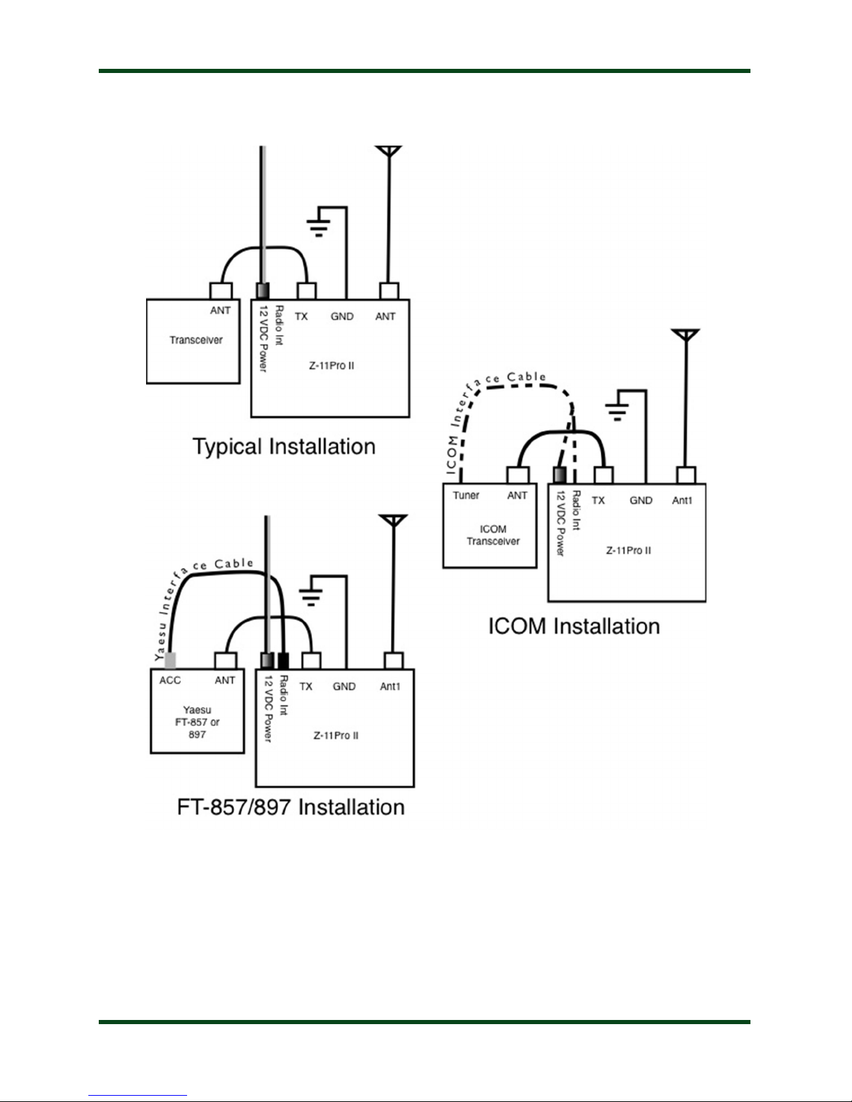
Connect the HF antenna jack on the transceiver to the TX jack on the back of the Z-11ProII,
using a 50 ohm coax cable rated 125 watts or higher.
Connect a 50-ohm antenna feedline coax to the ANT jack on the back of the Z-11ProII.
The Z-11ProII is designed to interface directly with many popular ICOM and Yaesu
transceivers, enabling one button tuning. In the case of ICOM radios, the optional interface cable
also powers the tuner.
For ICOM radios supporting the AH-3 or AH-4 external tuner, connect the 4-pin Molex
connector of the optional ICOM interface cable to the radio’s Tuner port. Then connect the 1/8”
stereo plug on the other end of the ICOM interface cable to the jack marked Radio on the rear of
the Z-11ProII. Connect the coaxial DC power plug of the ICOM interface cable to the 12 VDC
Power jack.
For Yaesu FT-857 and FT-897, use the optional Y-ACC cable and plug the red end marked
Radio into the transceiver’s ACC port. Plug the black end of the Y-ACC cable into the jack
marked Radio on the rear of the Z-11ProII.
Unless the Z-11ProII is being powered by the ICOM radio interface cable as above, you’ll
also need to plug in the supplied DC coaxial power cable2. This cable has a 2.5x5.5mm coaxial
plug on the end. Plug the coaxial plug into the 12 VDC Power jack on the rear of the Z-11ProII,
and connect the other end to a DC power source between 11 and 16 volts DC, capable of
supplying up to 300 mA. The red wire is positive.
Grounding the Z-11ProII tuner will enhance its performance and safety. LDG recommends
that you connect your tuner to a suitable ground. A common ground rod connected to buried
radials is ideal, but a single ground rod, a cold water pipe, or the screw that holds the cover on an
AC outlet can provide a serviceable ground. LDG strongly recommends the use of a properly
installed, high quality lightning arrestor on all antenna cables.
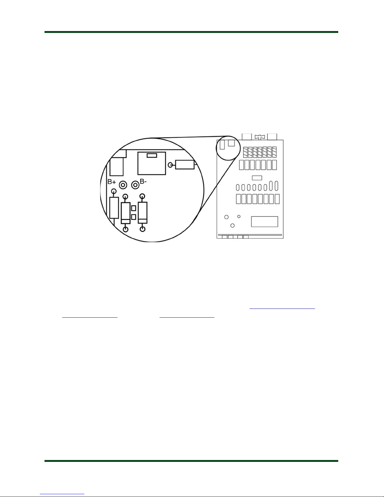
2Or, the Z-11ProIImay be powered by optional internal batteries. See the section on Battery Installation for more
details.

PAGE 8

PAGE 9
OPTIONAL INTERNAL BATTERY INSTALLATION
The Z-11ProII uses so little power that it is practical to install an internal battery pack,
making it more convenient to use for portable operation. The Z-11ProII has solder pads marked
B+ and B- near the power jack on the internal circuit board. These solder pads are provided to
allow easy installation of an internal battery pack.
The Z-11ProII will operate on any input voltage from 7 to 16 volts DC, which opens up a
wide range of internal battery possibilities. The most common would be 6 or 8 AA or AAA
batteries in a battery holder, with the holder double-sided-taped to the top of the relay bank. A
single 9V alkaline battery will work, as well, though it will need to be changed more frequently,
as 9V batteries typically have low (~300 mAh) capacity compared to AAA or AA batteries.
Appropriate battery holders are available from Radio Shack (www.radioshack.com), Digi-
Key (www.digikey.com), or Mouser (www.mouser.com).
To install a battery holder inside the Z-11ProII, remove the four screws that secure the cover,
and remove the cover from the unit. Locate the two solder pads marked B+ and B- near the DC
power jack. Solder the positive lead (normally red) of the battery pack to the B+ pad, and solder
the negative lead (normally black) to the B- pad. Be careful not to create any solder bridges or
shorts.
Secure the battery pack either to the underside of the lid, or to the top of the bank of relays,
using double-sided foam tape. Install batteries, and, if necessary, place tape over the batteries to
keep them secured in the holder. Replace the Z-11ProII cover, being careful not to pinch the
battery wires.

PAGE 10
Although the Z-11ProII may be operated on external DC power even while batteries are
installed, note that the Z-11ProII will not charge the internal batteries. If rechargeable batteries
are used, they must be removed from the Z-11ProII and recharged in an external charger.
Battery life will vary depending upon usage and the type of battery selected, but in most
cases, the batteries will last at least one year before requiring replacement.
Remove batteries from the Z-11ProII when the unit will not be used for an extended period
of time, to prevent possible damage due to battery leakage.
OPERATION
Basic Operation
The Z-11ProII is operated from the six front panel buttons. Each button has one or more
associated functions. The front panel labeling shows the primary and secondary function of each
button. Primary functions are accessed by pressing the associated button momentarily, or
pressing and holding the button. Secondary functions are accessed by first pressing and releasing
the FUNC button momentarily, and then pressing the associated button. If the FUNC button is
pressed accidentally, its action may be cancelled by pressing it a second time, or simply waiting
a few seconds for it to “time out”.

PAGE 11
The FUNC mode is indicated on the front panel LEDs by the LEDs quickly scrolling to the
right. When FUNC mode is cancelled, the LEDs scroll quickly to the left.
Basic Tuning
The Z-11ProII automates the process of matching an antenna load to the 50-ohm
characteristic impedance of coaxial cable feedline. Tuning occurs in one of two modes:
Automatic tuning mode, and Semiautomatic tuning mode.
When in Automatic tuning mode, the Z-11ProII will begin a tuning cycle any time that
there is forward RF power, and the measured SWR exceeds a preset threshold.
In Semiautomatic tuning mode, a tuning cycle will only begin when specifically requested
by pushing the TUNE button on the front of the tuner, or by pushing the TUNER/CALL button
on an appropriately interfaced compatible transceiver.
In either Automatic or Semiautomatic modes, the Z-11ProII employs two different types of
tuning cycles: a memory tuning cycle and a full tuning cycle. The Tune LED lights during
tuning.
The memory tuning cycle attempts to tune quickly, based on having previously tuned on the
present frequency selection. If the tuner previously was successful in tuning on the currently
selected frequency, the settings for that match will be loaded into the tuner relays, and checked to
see that an acceptable SWR match is found. If memory tuning fails to find a match, the tuner
falls through to a full tuning cycle.
A full tuning cycle “starts from scratch” and begins a fixed tuning sequence where the Z-
11ProII rapidly tries varying combinations of inductance and capacitance values, and then
zeroes-in on the best match possible. When the tuning cycle is complete, if an acceptable match
was found, the inductance and capacitance settings are saved in a memory associated with the
selected frequency, so that they may be recalled quickly in the future via a memory tuning cycle.
In this manner, the Z-11ProII “learns”; the longer you use it, the more closely it adapts itself
to the bands and frequencies used. Most users will probably use memory tuning most of the time;
it takes advantage of any saved tuning settings, but automatically defaults to a full tuning cycle if
no stored data is available.
In both cases, at the end of the tuning cycle, the carrier is held for 1.5 seconds after tuning is
complete, so that the final SWR may be read on the transceiver’s internal SWR meter or another
inline SWR meter, and the front panel LED will indicate the status of the tuning cycle.

PAGE 12
The tuner may also be placed in “bypass” mode where it is electrically removed from the
antenna system.
Toggle Bypass Mode
To toggle between bypassed and active mode, press the front panel TUNE button on the Z-
11ProII momentarily. All four LEDs will flash three times to indicate that the tuner is in bypass
mode. Press the front panel Tune button momentarily again to recall the previous tuner settings.
The LEDs will flash once to indicate that the tuner is no longer bypassed. This function may be
useful if you wish to compare antenna performance with and without the benefit of the tuner’s
matching network.

PAGE 13
Toggle Automatic / Semiautomatic Tuning Mode
As described above, the Z-11ProII employs a fully automatic and a semi-automatic tuning
mode. To toggle between the two, press and release the FUNC button, and then press the C
DN/AUTO button. When Automatic tuning mode is selected, the inner two LEDs will blink.
Press FUNC and then C DN/AUTO again, and the outer two LEDs will blink, indicating
Semiautomatic tuning mode.
Automatic Tuning Mode
When in Automatic Tuning Mode, simply key the radio in any transmit mode, and the Z-11
Pro II will begin tuning any time that the SWR exceeds a preset threshold. The Tune LED lights
during tuning, and the SWR LEDs indicate the SWR during the tuning process.
Continue transmitting (on AM or SSB, keep talking) until the tuning cycle is complete. A
memory tune is attempted first. If the memory tune does not find a previously stored match, a
full tuning cycle is initiated. When the tuning cycle is complete, the status of the tune will be
displayed on the LEDs, and then the final SWR will be displayed. See the section on Status
Indication for the possible tuning status indications.
Manual Memory Tuning
In addition to Automatic Tuning Mode, there are two semi-automatic tuning modes, memory
tuning mode and full tuning mode. Either can be requested at any time, including even when
the Z-11ProII is set for fully automatic tuning.

PAGE 14
To manually initiate a memory tuning cycle, press and hold the TUNE button for 0.5 to 2.5
seconds, and then release. The outer two front panel LEDs will light up to indicate that a
memory tuning cycle is requested.
If you are using the ICOM or Yaesu radio interface cable, the radio will automatically reduce
power, switch to CW mode, and transmit for as long as is required to complete the tuning cycle,
and then will return to the previous operating mode and power level when completed.
If you are not using the ICOM or Yaesu radio interface cable, you will need to key the radio
manually. In SSB or AM mode, begin talking into the microphone. Hold down the code key on
CW. Note that if your radio does not incorporate an SWR rollback circuit
3
, you will first need to
reduce power to 25 watts or less. In no case should you transmit more than 125 watts.
If the memory tune is not successful, the Z-11ProII falls through to full tuning cycle. At the
end of a tuning cycle, the LEDs cycle inwards to indicate a successful tune.
If using the Z-11ProII with an ICOM transceiver connected with the optional ICOM interface
cable, pressing the TUNER/CALL button on the transceiver will also initiate a memory tuning
cycle.
Manual Full Tuning
As with the memory tuning cycle, if your radio is not equipped with a rollback circuit, reduce
power to 25 watts or less before tuning. To manually initiate a full tuning cycle, press and hold
the TUNE button for more than 2.5 seconds and then release. The outer two front panel LEDs
will light up, then the inner two LEDs will light, to indicate that a full tuning cycle is requested.
3An SWR rollback circuit automatically reducesthe output power level when high SWR is present. Check your
radio’s manual to see if your radio uses a rollback circuit.

PAGE 15
If you are using one of the optional radio interface cables, the radio will automatically reduce
power, switch to CW mode, and begin transmitting while the full tuning cycle is in progress. If
not, key the radio (Talk into the mic on SSB or AM, close the key on CW) until the tuning cycle
is complete. Note that the SWR LEDs display the intermediate SWR results during tuning, and
will display the final SWR once tuning is complete.
Tuning Status / Error Indication
During normal operation, the front panel LEDs on the Z-11ProII are extinguished during
receive, and will light up to indicate the current SWR reading upon transmit. SWR levels may be
decoded as follows:
During or after tuning, the LEDs can indicate error conditions as well. Upon successful
completion of a tuning cycle, the outer two LEDs will light, then the inner two. Other error
conditions are explained in the table “Tuning Status Reports.”

PAGE 16
Tuning Status Reports
Condition Report
Successful tune
Outer LEDs light, then inner LEDs.
RF Lost during tune
All LEDs blink twice.
No RF found
All LEDs blink three times.
No match found
Leftmost three LEDs blink twice.

PAGE 17
ADVANCED OPERATION
Manual Inductor/Capacitor Adjustments
In some rare cases, after tuning, it may be desirable to adjust the inductance and capacitance
settings that the Z-11ProII came up with during the tuning process. This is more likely to occur
when attempting to tune an antenna far from its resonant frequency.
The C Up, C Dn, L Up, and L Dn buttons may be used to increment or decrement the
amount of capacitance or inductance, respectively. A momentary press of any of these buttons
increments or decrements the value by one unit. Repeatedly press one of these buttons to
increment or decrement multiple times, or simply hold the button and the button will auto-repeat.
You may also transmit while incrementing or decrementing, so that the SWR value is displayed.
High / Low Z Relay Adjustment
In addition to being able to manually control the inductor and capacitor value of the Z-
11ProII, it is also possible to manually set the high/low impedance relay, which determines
whether the tuner is an L-C configuration or a C-L configuration. To toggle the state of the
high/low impedance relay, press FUNC, then L Up (Hi/Lo Z). The LED display will indicate
one of two patterns to confirm the setting.
Manual Memory Store
Once manual adjustments are complete, press FUNC and then TUNE (Store) momentarily,
to store the current relay settings in the memory associated with the frequency last transmitted
upon.

PAGE 18
Set Automatic Tuning SWR Threshold
When the Z-11ProII is in fully automatic tuning mode, it begins tuning any time RF is
present, and the SWR exceeds a preset threshold. That threshold may be programmed to any
desired value between 1.5:1 and 3.0: To set the SWR threshold, press FUNC then L Dn /
Thresh. The LEDs will show the current setting of the SWR threshold. Press FUNC then L Dn /
Thresh again to advance through the possible settings.

PAGE 19
COMMAND SUMMARY
Function Button Sequence
Toggle Auto / Semi mode FUNC then C Dn
Auto Tune Threshold FUNC then L Dn
High / Low Z Select FUNC then L Up
Full Tuning Cycle Hold TUNE for >2.5 seconds
Memory Tuning Cycle Hold TUNE for 0.5 to 2.5 seconds
Toggle Bypass Mode Press TUNE momentarily
APPLICATION INFORMATION
Mobile Operation
The Z-11ProII is perfectly suited to mobile operation. It can be installed under the dashboard
along with the transceiver, or mounted remotely. The only requirement is that the tuner remains
dry.
If it is desired that the Z-11ProII is positioned farther from the transceiver than the optional
cable length allows, a custom cable will need to be constructed. This can be accomplished in
two ways: Cut the optional cable and solder a jumper wire between all the connections, or
purchase new connectors and cable to construct a custom-length interface cable from scratch.
MARS/CAP Coverage
The Z-11ProII provides continuous tuning coverage over its specified range; not just in the
ham bands. This makes it useful for MARS or CAP operation, or any other legal HF operation.

PAGE 20
THEORY OF OPERATION
Some basic ideas about impedance
The theory underlying antennas and transmission lines is fairly complex, and in fact employs
a mathematical notation called “complex numbers” that have “real” and “imaginary” parts. It is
beyond the scope of this manual to present a tutorial on this subject
4
, but a little background will
help in understanding what the Z-11ProII is doing, and how it does it.
In simple DC circuits, the wire resists current flow, converting some of it into heat. The
relationship between voltage, current, and resistance is described by the elegant and well-known
“Ohm’s Law”, named for Georg Simon Ohm of Germany, who first discovered the principle in
1826. In RF circuits, an analogous but more complicated relationship exists.
RF circuits also resist the flow of electricity. However, the presence of capacitive and
inductive elements causes the voltage to lead or lag the current, respectively. In RF circuits, this
resistance to the flow of electricity is called “impedance”, and can include all three elements:
resistive, capacitive, and inductive.
The output circuit of a transmitter consists of inductors and capacitors, usually in a
series/parallel configuration called a “pi network”. The transmission line can be thought of as a
long string of capacitors and inductors in series/parallel, and the antenna is a kind of resonant
circuit. At any given RF frequency, each of these can exhibit resistance, and impedance in the
form of capacitive or inductive “reactance”.
Transmitters, transmission lines, antennas, and impedance
The output circuit of a transmitter, the transmission line, and the antenna all have a
characteristic impedance. For reasons beyond the scope of this document, the standard
impedance is nominally 50 ohms resistive, with zero capacitive and zero inductive components.
When all three parts of the system have the same impedance, the system is said to be “matched”,
and maximum transfer of power from the transmitter to the antenna occurs. While the transmitter
output circuit and transmission line are of fixed, carefully designed impedance, the antenna
presents 50-ohm, non-reactive load only at its natural resonant frequencies. At other frequencies,
4For a very complete treatment of this subject, see anyedition of theARRL Handbook for RadioCommunications
(previously the Handbook For Radio Amateurs).
Table of contents
Other LDG Tuner manuals