LDG Z11 User manual

Z
-
11
Automatic Antenna Tuner
Manual
Version 1.5G
LDG Electronics
1445 Parran Road, PO Box 48
St. Leonard MD 20685-2903 USA
Phone: 410-586-2177 Fax: 410-586-8475

-1-
Introduction: Congratulations on choosing the LDG Z11 tuner. The Z11 is a full featured low power
automatic or semiautomatic antenna tuner designed for the HF ham bands (1.8 to 30 MHz). It will
work with virtually any transceiver or transmitter providing between 0.1 and 30 watts continuous RF
output (60 watts SSB or CW). The tuner uses the highly versatile “Switched L" configuration with
256 capacitor, 256 inductor and High/Low impedance settings to provide over one hundred and
thirty thousand possible tuning combinations. The "L" network will match practically any coax-fed
antenna (dipole, vertical, sloper, beam, etc). Long wires, and dipoles fed with ladder line can be
matched using the LDG RBA-1 external balun, sold separately. Regardless of antenna type, tuning
time is between 0.1 and 3.0 seconds, typically about 1.5 seconds.
The Z11 uses latching relays to switch tuning components in the “L” network. These relays hold the
tuning configuration even when power is removed; once matched, the tuner automatically enters a
low-power mode where it draws only 0.8 milliamps. Placing the tuner into “Standby” reduces power
consumption to zero; the latching relays maintain the tuned configuration indefinitely. During tuning,
the Z11 may draw up to 300 milliamps, but only for a few seconds. These exclusive LDG features
make the Z11 ideal for portable, battery-powered HF operation.
An important word about power levels: The Z11 is intended for low-power operation only. The
Z11 is rated at 30 watts continuous power input, at most. On CW and SSB, whose duty cycle is
approximately 50%, this translates into 60 watts peak RF into the tuner. Many ham transmitters and
transceivers output 100 watts or more; this power level will definitely damage your Z11. Be sure to
observe the 60 watt power limitation for CW and SSB operation, and 30 watts when tuning, or using
FM, RTTY or any other 100% duty cycle mode. Most transceivers and transmitters have a level
control to adjust the output. Use a good quality wattmeter to find the setting that corresponds to
these rated power output levels, and note the setting of the level control. Never exceed that level in
operation with the Z11.
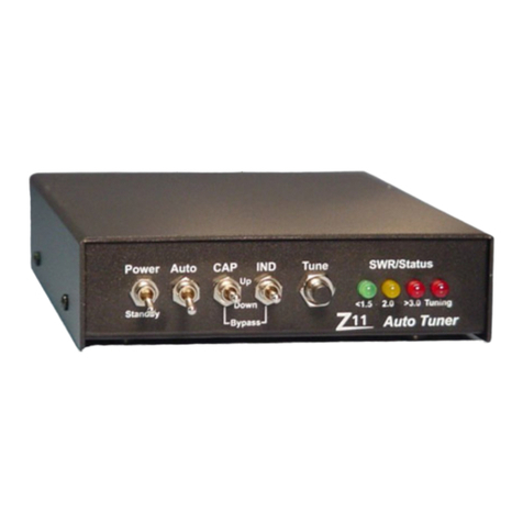
Front panel controls: The Z11 is operated from the front panel through four switches, four LEDs
and one pushbutton. Refer to the index numbers on photo below.

-2-
LEDs: Three LEDs show SWR while tuning or transmitting: green (6) indicates an SWR of less than
1.5, green and yellow together is 1.5 -2.0, yellow (7) alone is 2.0 -2.5, yellow and red togeth

-3-
and stop automatically. If the Tune button is pressed and there is less than 0.1 watts of power, the
four front LEDs will flash to indicate that there was not enough RF to tune properly.
The Tune button has some additional functions when used in combination with other switches.
Pressing the Tune button and Ind Up switch together will set the High/Low impedance relay to the
High impedance position. The Tuning LED (red) will flash to indicate the change. Pressing the Tune
button and Ind Down switch together will switch the High/Low impedance relay to the Low
impedance position. The 1.5 SWR LED (green) will flash to indicate the change. This allows you to
manually adjust the match as needed. Again, you will rarely need to use this function; it is provided
for maximum flexibility. Note that even if you manually set the High/Low impedance relay, it will
automatically be reset as needed by the processor the next time the tuning cycle is started.
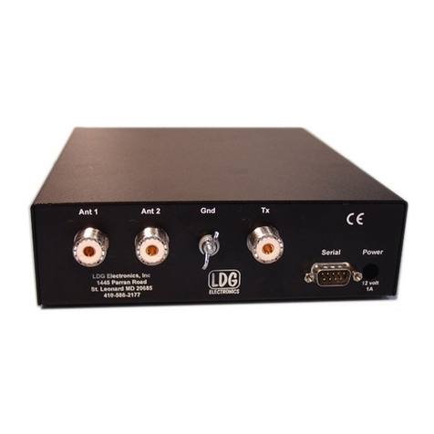
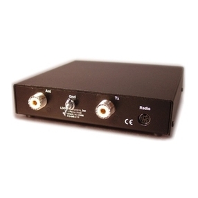
Back Panel Connections: The back panel has standard SO-239 jacks for connecting to the
antenna and transmitter; use standard PL-259 plugs. A coaxial power jack (5.5 by 2.5 mm, center
pin positive) provides DC power to the tuner. The power supply must provide between 11 and 20
volts DC at 200 milliamps for up to three seconds. If your transceiver or transmitter operates on 12
volts DC, the Z11 can be powered by the same source.
Another power option is two “9 volt” batteries in series, providing about 14 to 18 volts DC. For
rechargeable 9V batteries, you can expect to get about 500 tuning cycles on a charge. Regular 9V
alkaline batteries will last longer, but cannot be recharged.
Operation: Connect your transceiver or transmitter to the jack marked “Transmitter”, and the
antenna to the jack marked “Antenna”. Connect the power supply to the coaxial power jack. Your
Z11 is now ready to use.
Turn on the unit by placing the Power switch in the Power position (up). This initializes the
microprocessor; all four LEDs will flash once to indicate a successful power-up. If previously tuned
prior to the last power-down, the Z11 will retain the tuned state on power-up; the Z11 does not reset
on power-up.
Set the Auto switch to either Auto (up) or Manual (down) as desired. We recommend you start in
the Manual (down) mode until you become familiar with the Z11, and with your antenna.

-4-
Set your transmitter or transceiver to transmit a continuous carrier of at least 0.1 watt and not more
than 30 watts output. CW or FM are usually the most convenient modes for tuning.
While transmitting the carrier, press and release the Tune pushbutton on the Z11 front panel. The
tuning cycle will start, as indicated by the red Tuning LED. You will also hear the latching relays
cycling as the processor tries different combinations of inductance and capacitance, searching for a
match; this makes a fairly loud “buzzing” noise. You can observe the SWR on the indicator LEDs; it
will decrease as the Z11 approaches a match (watch closely; it happens fast). The tuning cycle will
end automatically in a few seconds with the LEDs indicating the final match. Unkey your transmitter;
the tuning process is complete.
In the unlikely event that the Z11 fails to achieve a satisfactory match, you can manually adjust
capacitance and inductance using the front panel switches. Key your transmitter again and adjust
up or down while observing the SWR on the indicator LEDs. Unkey when you find a satisfactory
match.
In either tuning mode (Auto or Manual), if power (either RF or DC) is removed before the tuning
cycle is complete, the LEDs will all go out and tuning will stop unmatched. Correct the problem to
restore RF and DC power, and begin a new tuning cycle.
After tuning, you can leave the Power switch in the Power position (up) and the mode switch in Auto
(up). If you shift frequency significantly, causing the SWR to exceed 3.0, the Z11 will automatically
begin a new tuning cycle when you transmit a carrier. In many cases, however, you can set the
Power switch to Standby (down), eliminating current drain entirely. You can always power up and
tune in a few seconds any time you need to.
A word about tuning etiquette: Be sure to pick a vacant frequency to tune. With today’s crowded
ham bands, this is often difficult. However, do your best to avoid interfering with other hams as you
tune. The Z11’s very short tuning cycle, usually only a second or so, minimizes the impact of your
tuning transmissions.
Performance: The performance of the Z11 will surprise you. It will match an amazing range of
antenna types, locations and setups. Using an Autek RF-1 analyzer, we found that the Z11 would
consistently tune impedances from about 6 ohms to about 850 ohms. This corresponds to an SWR
of about 10:1.
Here are some informal field test results to give you a feeling for the Z11’s capabilities:
Antenna Performance
Full-sized 40 meter dipole
30 feet above ground
Tuned practically anywhere from 3.1 to 30 MHz, with some problems at
19 and 28 MHz. In these cases, the Z11 usually achieved an SWR
of 2.0 automatically; we then used the manual switches to get
below 1.5.
Antron-99 Tuned practically anywhere from 5 to 30 MHz. The auto mode
worked very well over the whole range.
3-element tri-band beam
(20, 15 and 10 meters)
70 feet above ground
Tuned all of the ham bands (including WARC) except 160 and 80.
Some problems finding a match around 27.2 MHz, but we got around
it by moving to 27.0, letting the Z11 find a match, then moving
back to 27.2.
80-meter inverted “Vee” Tuned everything from 3.1 to 30 MHz. On 160 meters it found
good matches from1.8 to 1.9 MHz.

-5-
Even though the Z11 will match a very wide variety of antennas and frequency bands, achieving a
match far from resonance is very inefficient; much of your transmitter’s power will be dissipated in
the tuner, never reaching the antenna. For best results, your antenna should be as close to
resonance as circumstances permit.
The Z11 will match some balanced or random wire antennas connected to the SO-239 output jack,
but again, it will be somewhat inefficient. For best results, balanced and random wire antennas
should be fed through a balun such as the LDG RBA-1.
The tuning bandwidth of the Z11 (usable frequency excursion before exceeding a 1.5 SWR) varies
considerably with frequency band, ranging from about 75 kHz on 80 meters, to about 400 kHz on
10 meters. In Auto mode, the Z11 will automatically retune as necessary when you transmit a
carrier after changing frequency.
One Touch Tune (OTT) Operation: The Z11 can also be interfaced to directly control an FT-817.
The One Touch Tune interface from W4RT Electronics (www.w4rt.com) can be purchased
separately. With the OTT installed, the user simply presses the tune button the Z11 and the OTT
sends a command to the 817 to transmit a carrier while the tuner is tuning. While not required for
operation with the FT-817, the OTT makes changing bands and re-tuning a snap.
Care and Maintenance: Your Z11 tuner is essentially maintenance-free, and rugged enough for
normal field use. The outer case may be cleaned as needed with a soft cloth slightly dampened in
household cleaning solution. As with any modern electronic device, the Z11 can be damaged by
temperature extremes, water, impact or static discharge.
Technical Support: We are happy to help you with your Z11. Telephone technical support is
available at 410-586-2177 weekdays from 9 am to 5pm Eastern time. Inquiries by Fax at 410-586-

-6-
Warranty and Service: Factory assembled units are warranted against defects in parts or
workmanship for one year from purchase. Kits are warranted against defects in parts only for one
year from purchase. This warranty applies to the original purchaser only; it is not transferable. Units
returned for warranty service must be accompanied by a copy of the receipt showing the
purchaser’s name and the date of purchase. All returns must be shipped to us pre-paid; we will not
accept units with postage due. A return form is provided on our web site for your convenience.
If you need to return your Z11 to us for service, package it carefully, keeping in mind that we will re-
use your packaging to return the unit to you. A self-addressed return shipping label, while not
required, will help insure speedy and accurate delivery of your repaired unit. Include a full
description of the problem, along with your name, address and a phone number or e-mail where we
can reach you with any questions. Repair turnaround can vary from 2 to 6 weeks, depending on the
particular problem.
We will be glad to service your Z11 after the warranty period. We will notify you of repair charges by
phone or e-mail, and bill you after repairs are completed.
Firmware upgrades: From time to time we will release upgraded firmware for the Z11, refining
operation and adding features. Your Z11 is not field programmable; you will have to remove the
present chip and replace it with the upgrade chip. To remove the chip (68HC11, U1(location D7 on
parts placement grid)) you will need an appropriate tool. A PLCC extraction tool is ideal, but if you
don’t have one you can fashion a substitute from an ordinary paperclip. Straighten the paper clip,
then bend it into a “U” shape. Use pliers to bend the last 1/8” of each end toward the center (see
illustration).
The extraction tool fits into opposite corners of the 68HC11socket; the bent ends will lift the chip
from beneath. Touch a ground point to avoid static discharge damage, and remove the case top.
Insert the tool and pull gently and evenly on both sides to extract the chip. Press the upgrade chip
into the socket, observing the small diagonal corner key. Replace the case top; your upgraded Z11
is ready for service.
You will return the old processor chip to LDG; the upgrade is sold by exchange only. The
processors are recycled and reprogrammed to minimize future upgrade costs. Upgrades will cost
$10-20 with chip exchange, and will be announced on our web site when available.
Feedback: If you have an idea to improve our software or hardware, please send us a description.
If we incorporate your idea in the Z11, we'll send you a free upgrade as a “thank you”.
We encourage everyone who uses the Z11 to contact us (card, letter or e-mail preferred) telling us
how well it works for you. We are also always looking for photographs of the Z11 in use; we
frequently place such pictures in the LDG Newsletter and on our Web site
(www.ldgelectronics.com).

123456
A
B
C
D
654321
D
C
B
A
Title
Number RevisionSize
C
Date: 7-Oct-2002 Sheet of
File: C:\Projects\Protel\Genes_Protel_Files\Protel99SE\QRP\QRPZ131.ddbDrawn By:
R15
1K
C32
680pf
C29
82pf
C8
0.01uf
31
RSIP1B
1K
R20
1K
C14
100pf
AS 4
R/W 6
E5
B0 42
B1 41
B2 40
B3 39
B4 38
B5 37
B6 36
B7 35
C0 9
C1 10
C2 11
C3 12
C4 13
C5 14
C6 15
C7 16
A0 34
A1 33
A2 32
A3 31
A4 30
A5 29
A6 28
A7 27
D2 22
D3 23
D4 24
D5 25
E0 43
E1 45
E2 47
E3 49
E4 44
E5 46
E6 48
E7 50
VDD
26
VSS
1
EXTAL
7
XTAL
8
RESET
17
D1
21
D0
20
VRL
51
MODB
2
MODA
3
VRH
52
IRQ
19
XIRQ
18
U1
68HC11
Vin
1
GND
3
+5V 2
U4
7805
+5
15
RSIP1D
1K
110
RSIP1I
1K
19
RSIP1H
1K
17
RSIP1F
1K
18
RSIP1G
1K
16
RSIP1E
1K
C18
1uf
+5
C15
10pf
C16
10pf X1
~4.5Mhz
R16
1M
C12
0.01uf
C7
0.01uf
C9
10uf C13
0.01uf
D3
1N4001
1 4
RSIP1C
1K
21 RSIP1A
1K
+5
J1
Transmittr
3
4
5
T1
J2
Antenna
L1
0.11uh L2
0.22uh L3
0.39uh L4
0.59uh L5
1.25uh L6
2.5uh L7
5.0uh L8
10.0uh
C2
100pf
R19
3.3K
R18
150
D1
1N4148 D2
1N4148
1 2
R17
100
12 R21
100
C3
0.01uf C4
0.01uf
C6
0.01uf
C5
0.01uf
R23
100K
R22
100K
0
TP1
REV
0
TP2
FWD
C25
10pf C26
10pf C27
10pf C28
39pf C30
150pf C31
330pf C33
680pf C34
680pf
1
2
J4
+
INDUP
INDDN
CAPUP
CAPDN
GREEN
YELLOW
RED1
RED2
AUTOSEMI
TUNESW
Z-11 Auto Tuner
Version 1.4G
1 1 AA3AV
Reset
Set
+
+
K1
Reset
Set
+
+
K2
Reset
Set
+
+
K3
Reset
Set
+
+
K4
Reset
Set
+
+
K5
Reset
Set
+
+
K6
Reset
Set
+
+
K7
Reset
Set
+
+
K8
Reset
Set
+
+
K9
Reset
Set
+
+
K10
Other manuals for Z11
1
Table of contents
Other LDG Tuner manuals
Popular Tuner manuals by other brands

Sirius Satellite Radio
Sirius Satellite Radio SiriusConnect SCC1C installation guide

Strings.ie
Strings.ie T1 instruction manual

Technics
Technics ST-8044 Service manual

Musical Fidelity
Musical Fidelity A5 Instructions for use

Sirius XM RAdio
Sirius XM RAdio XHD2H1 user guide

Pioneer
Pioneer FH-P5000MP Operation manual