LDG OT-11P User manual

OT-11P
Automatic Antenna Tuner
For Ten-Tec Orion
Manual Version 1.1
LDG Electronics
1445 Parran Road, PO Box 48
St. Leonard MD 20685-2903 USA
Phone: 410-586-2177
Fax: 410-586-8475
www.ldgelectronics.com
Copyright © LDG Electronics 2006. All rights reserved.

2
OT-11P
Automatic Antenna Tuner
For the Ten-Tec Orion
Introduction 3
Specifications 3
OT-11P Auto Tuner Overview 4
Installation 6
Operation 11
Theory Of Operation 12
Some Basic Ideas About Impedance 12
Transmitters, Transmission Lines, Antennas and Impedance 12
The LDG OT-11P 14
A Word About Tuning Etiquette 15
Care and Maintenance 15
Technical Support 15
Warranty and Service 15
Firmware Upgrades 16
Feedback 16

3
Introduction
Congratulations on selecting the OT-11P tuner for your Ten-Tec Orion and Orion II transceiver.
This tuner, when installed, will be fully integrated with your transceiver, and will be controlled by
the radio's user interface. Your OT-11P will quickly and automatically match an amazing variety
of antennas.
LDG pioneered the automatic, wide-range switched-L tuner in 1995. From its laboratories near
the nation’s capitol, LDG continues to define the state of the art in this field with innovative
automatic tuners and related products for every amateur need.
Specifications
• Fully integrated with the Orion and Orion II transceiver
• 200 memories for instantaneous frequency or band changing
• Automatic recall of last tuned setting on power-up
• Tuning time: 0.1 to 4 seconds full tune, < 0.1 second memory tune
• Frequency coverage: 1.8 to 30 MHz.
• Tunes 6 to 1000 ohm loads (16 to 150 ohms on 6M), 6 to 4000 ohms with
optional 4:1 Balun (LDG RBA-1)
• For Dipoles, Verticals, Vs, Beams or and Coax Fed Antenna
• Optional external Balun allows tuning of random length, long wire or ladder line
fed antennas
• Powered directly by the Orion radio
IMPORTANT SAFETY WARNING
Never install antennas or transmission lines over or near
power lines. You can be seriousl
y
in
j
ured or killed if an
y
part
of the antenna, support or transmission line touches a power
line. Alwa
y
s follow this antenna safet
y
rule: the distance to
the nearest power line should be at least twice the len
g
th o
f
the lon
g
est antenna
,
transmission line or su
pp
ort dimension.

4
OT-11P Auto Tuner Overview
Your OT-11P comes fully assembled, aligned and ready to install. You will install the tuner
inside your Orion transceiver, resulting in a fully integrated internal tuner. After installation, your
OT-11P tuner will be controlled by the Orion's front panel TUNE button.
Installation is straightforward; you will mount the tuner inside your Orion transceiver, remove
one coax jumper, install three plugs and solder one connection. These are simple steps, well
within the abilities of anyone with basic electronic assembly skills. Simply follow the step-by-
step directions, referring to the accompanying illustrations. Work patiently, read through each
step completely before proceeding and check your work often.
Your workplace should be uncluttered, well lighted and well ventilated, and protected from static
discharge. A grounded static mat is ideal, but you should at least be able to touch a ground point
(light switch, water pipe, etc) from time to time to avoid static buildup.
Installing the OT-11P according to these instructions does not void your Ten-Tec warranty.

5
A word about power levels
Your OT-11P is custom designed specifically for the Orion transceiver and its power levels.
LDG does not recommend using the OT-11P in any other application. If you choose to do so,
never exceed 125 watts peak power input to the tuner. A minimum of 0.1 watts is required to
activate the tuner.
Required Tools:
You will need a few basic electronic assembly tools to install your OT-11P:
Small soldering iron, 25-40 watts (a temperature-controlled iron is preferred)
Rosin-core or other solder intended for electronic assembly (NEVER use acid core solder for
electronic assembly)
Medium cross-point screwdriver, small hex or star driver
Small pliers
Small wire cutters
Tack Soldering
In one step, you will be instructed to “tack solder” a wire. This refers to soldering a wire end to a
pin with no hole to accept the wire. Simply hold the wire against the pin, heat with your soldering
iron, and apply a small amount of solder. Hold the wire in place until the solder cools. It will help
to tin the wire first, flowing solder onto the wire before soldering it into place.

6
Installation
Before installing your OT-11P tuner, you should upgrade the radio's firmware to the latest
version. Consult the radio's manual and the Ten-Tec web site for instructions on how to do this.
When the firmware upgrade is complete, proceed with installing the tuner.
With your Orion powered down and disconnected from the DC power supply, remove the top and
bottom covers from the radio. Using a medium cross-point screwdriver, remove four screws from
the sides of the radio (two on each side). Using a cross-point or star tool, remove the small screws
from the back of the covers. Set these and all other screws aside for later reassembly; they will all
be reused. The Orion's speaker cone will be exposed throughout the installation; take care not to
damage it.
Turn the radio bottom-up on your workbench with the front panel facing you; directions for
right/left and front/back are relative to this position (front means nearest the front panel). You
will install the OT-11P tuner in the right rear compartment, connecting it to the radio via the five
cables attached to the tuner (one black and one white pair (Control), one red (+12 vdc), and two
coaxial cables (RF IN and RF OUT).
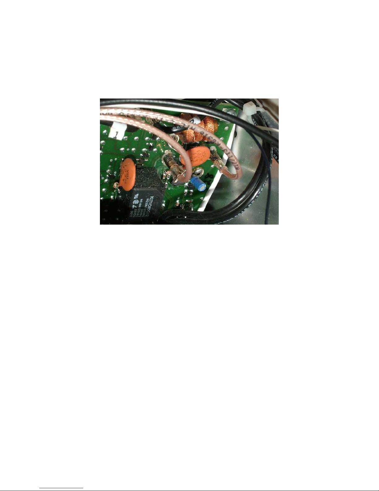
Step 1: Carefully place the OT-11P into position in the right rear compartment of the radio. Be
careful not to pinch or foul any of the wires connected to the tuner. The OT-11P goes in with the
components up (looking down into the bottom of the radio) with the red toroid inductors to the
left. Align the four mounting holes in the tuner with the four holes in the Orion chassis. Secure
with the four small cross-point screws, spacers and washers provided. Hand tighten only; do not
overtighten.
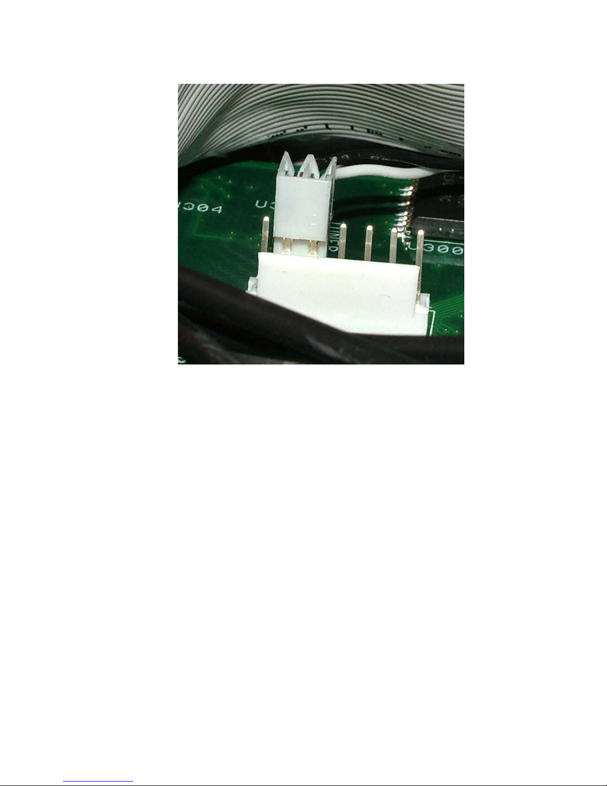
Step 2: Attach the control line. In this step, you will remove the Orion's front panel, attach the
black and white control cable to a connector on the inside of the front panel, then reinstall the
front panel. Follow these sub-steps:
Step 2.1: Don't Panic! Yes, we know you ponied up three large for your Orion, but
removing the front panel is actually a lot easier than it sounds. The Orion front panel is an
integrated assembly that comes off in one piece. You do not have to remove any knobs or
other controls. There are many cables connecting the panel to the radio chassis, but there
is enough slack to let you work leaving all connected.
Step 2.2: Remove the 12 small screws that hold the front panel to the chassis: 4 each on
the top and bottom, 2 on each side. Each screw goes through a black plastic tab on the
outside of the chassis (note for later reassembly). Set the screws aside for later
reassembly.
Step 2.3: Gently pull the front panel assembly away from the chassis. Be careful not to
stress any of the wires connection the front panel to the chassis.

7
Step 2.4: Locate connector J11, a white 7-pin connecter on the inside of the panel
assembly near the center. There is nothing connected to it in the stock radio. Note: Some
Orions have a blank connector here to prevent pin damage. You can remove the blank
connector to install the black and white tuner control connector.
Original Orion Orion II
Step 2.5: Route the black and white control cable from the OT-11P tuner through the
round grommet in the back of the front-panel compartment. It's a snug fit through the
grommet, but you can gently work it through.
Step 2.6: Attach the black and white cable to J11. The connector goes on the 2nd and 3rd
pins, counting from the left. Orient the connector with the wires going "down" toward the
top of the front panel (remember, the radio is upside down at this point).

8
Step 2.7: Reattach the front panel, making sure you don't pinch or bind any wires.
Remember, the black tabs on the edge of the front panel go on the outside of the chassis.
Step 2.8: Take a short coffee break; the worst is over.
Step 3: Route the red wire connected to the OT-11P through the notch in the radio's center-right
shield panel, to the front right compartment of the radio. Locate the small circuit board there, and
the black multi-pin connector on the left side. Locate the two pins closest to the back of the radio.
Carefully tack solder the end of the red wire from the OP-11 to either or both of these pins. Check
your work and make sure there are no solder bridges to the adjacent pins.

9
\
Step 4: Carefully route the two coaxial cables attached to the OT-11P through the round grommet
at the center rear of the radio. The coax cable connectors have flanges, pushing them through one
at a time will make it easier. Route the two cables between the left rear shield panel and the
circuit board mounted vertically in the left rear, to the area directly behind the two SO-239
antenna jacks.
Step 5: Turn the radio over and locate the two coax PC jacks on the PC board mounted flush
against the back of the radio, directly behind the ANT 1 SO-239 antenna jack. There is a jumper
connecting these two jacks. Carefully remove the jumper and discard it (or, you can save it in
case you want to uninstall your OT-11P tuner, but why would you ever want to do that?).

10
Step 6: Carefully insert the cable coming from the front of the OT-11P into the jack furtherest
from the right edge of the PC board. This is the cable that is connected to the OT-11P through the
small toroid sensor coil labeled T1 on the tuner. Insert the other cable into the jack nearest the
edge of the PC board. Double check to make sure you have the correct cable in the correct jack.
Step 7: Carefully check your work. Look especially for solder splashes or bridges. Make sure all
wires are routed neatly, and that none will be pinched or fouled when you replace the case covers.
Step 8: Replace the case covers and reconnect antenna and power cables.
Congratulations! You have completed installation of your OT-11P automatic tuner. Proceed to
Operation.

11
Operation
Enabling the tuner:
In the Orion TX setup menu, check the "Internal Tuner" setting. If it is set to "disabled",
change it to "enabled". You only have to do this once, the first time you use the tuner. However,
you will have to repeat this setting if you ever perform a hard reset on the radio.
Normal operation:
Operation of your OT-11P tuner is controlled by the Orion's TUNE button. To tune, simply set
the radio to the desired operating frequency, then press and release the TUNE button on the
radio's control panel. A memory tuning cycle will begin; stored tuning parameters will be used if
available. If no stored parameters are available, the tuner will automatically begin a full tuning
cycle. The radio will transmit a carrier of about 20 watts, and the tuner will cycle. You may hear
the relays switching in and out; they make a fairly loud buzzing noise. The tuning cycle will
automatically end in a few seconds. The radio will unkey, with power set back to the normal
level. The word "tuned" will appear on the display, and the achieved SWR (usually less than
1.5) will be momentarily displayed.
As you use your OT-11P it will automatically memorize tuning parameters for up to 200 of your
favorite frequencies and bands. When you re-tune on or near that frequency again, your OT-11P
will restore these parameters almost instantly, much faster than a full tuning cycle. Your OT-11P
literally "learns" as you use it.
Bypass mode:
To bypass the tuner and operate direct the antenna without matching, simply push the TUNE
button again. The "tuned" indication will disappear, and the tuner will be temporarily disabled.
To tune again, just press TUNE button.
If you change bands on your Orion, the radio will issue a bypass command to the tuner. To tune
on the new band, simply press and release the TUNE button and the tuner will retune for that
band.
Forcing a full tune:
You can, if you wish, force the tuner to run a full tuning cycle even when there are tuner
parameters stored for that operating frequency. Press and hold the TUNE button for the duration
of the tune. You can tell the tune cycle is over when the relays stop clicking. If you release the
TUNE button in the middle of a full tune, the next tune will be a full tune cycle.
Each time you power up your Orion, the OT-11P will automatically reset the last-used tuning
parameters, so you don't have to retune each time. Memory operation is fully automatic, and
requires no input from you.
Disabling the tuner:
If you wish to disable the tuner altogether, set the "Internal Tuner" setting to "disabled" in the
Orion setup menu. Thereafter, pressing the TUNE button will not begin a tuning cycle. To enable
the tuner again, change the "Internal Tuner" setting back to "enabled".

12
Theory Of Operation
Some Basic Ideas About Impedance
The theory underlying antennas and transmission lines is fairly complex, and in fact employs a
mathematical notation called “complex numbers” that have “real” and “imaginary” parts. It is
beyond the scope of this manual to present a tutorial on this subject1, but a little background will
help you understand what your OT-11P is doing, and how it does it.
In simple DC circuits, the wire resists the current flow, converting some of it into heat. The
relationship between voltage, current and resistance is described by the elegant and well-known
“Ohm’s Law”, named for Georg Simon Ohm of Germany, who first discovered it in 1826. In RF
circuits, an analogous but far more complicated relationship exists.
RF circuits also resist the flow of electricity. However, the presence of capacitive and inductive
elements causes the voltage in the circuit to lead or lag the current, respectively. In RF circuits
this resistance to the flow of electricity is called “impedance”, and can include all three elements:
resistive, capacitive, and inductive.
The output circuit of your transmitter consists of inductors and capacitors, usually in a
series/parallel configuration called a “pi network”. The transmission line can be thought of as a
long string of capacitors and inductors in series/parallel, and the antenna is a kind of resonant
circuit. At any given RF frequency, each of these can exhibit resistance, and impedance in the
form of capacitive or inductive “reactance”.
Transmitters, Transmission Lines, Antennas and Impedance
The output circuit of your transmitter, the transmission line, and the antenna all have a
characteristic impedance. For reasons too complicated to go into here, the standard impedance is
about 50 ohms resistive, with zero capacitive and inductive components. When all three parts of
the system have the same impedance, the system is said to be “matched”, and maximum transfer
of power from the transmitter to the antenna occurs. While the transmitter output circuit and
transmission line are of fixed, carefully designed impedance, the antenna presents a 50 ohm, non-
reactive load only at its natural resonant frequencies. At other frequencies, it will exhibit
capacitive or inductive reactance, causing it to have an impedance different from 50 ohms.
When the impedance of the antenna is different from that of the transmitter and transmission line,
a “mismatch” is said to exist. In this case, some of the RF energy from the transmitter is reflected
from the antenna back down the transmission line, and into the transmitter. If this reflected
energy is strong enough it can damage the transmitter’s output circuits.
1For a very complete treatment of this subject, see any edition of the ARRL Handbook for Radio
Communications (previously the Handbook For Radio Amateurs)
Inductive
Reactance
Capacitive
Reactance

13
The ratio of transmitted to reflected energy is called the “standing wave ratio”, or SWR. An SWR
of 1 (sometimes written 1:1) indicates a perfect match. As more energy is reflected, the SWR
rises to 2, 3 or higher. As a general rule, modern solid state transmitters must operate with an
SWR of 2 or less. Tube exciters are somewhat more tolerant of high SWR. If your 50 ohm
antenna is resonant at your operating frequency, it will show an SWR close to 1. However, this is
usually not the case; operators often need to transmit at frequencies other than resonance,
resulting in a reactive antenna and a higher SWR.
FR
FR
SWR /1
/1
−
+
=
SWR is measured using a device called an “SWR bridge”, inserted in the transmission line
between the transmitter and antenna. This circuit measures forward and reverse power from
which SWR may be calculated (some meters calculate SWR for you). More advanced units can
measure forward and reverse power simultaneously, and show these values and SWR at the same
time.
An antenna tuner is a device used to cancel out the effects of antenna reactance. Tuners add
capacitance to cancel out inductive reactance in the antenna, and vice versa. Simple tuners use
variable capacitors and inductors; the operator adjusts them by hand while observing reflected
power on the SWR meter until a minimum SWR is reached. Your LDG OT-11P automates this
process.
No tuner will fix a bad antenna. If your antenna is far from resonance, the inefficiencies inherent
in such operation are inescapable; it’s simple physics. Much of your transmitted power may be
dissipated in the tuner as heat, never reaching the antenna at all. A tuner simply “fools” your
transmitter into behaving as though the antenna were resonant, avoiding any damage that might
otherwise be caused by high reflected power. Your antenna should always be as close to
resonance as practical.
where F = Forward power (watts), R = Reflected power (watts)
SWR Lookup Table
Find SWR at intersection of
forward power column and
Forward Power (Watts)
20 30 40 50 60 70 80 90 100
2 1.92 1.70 1.58 1.50 1.45 1.41 1.38 1.35 1.33
4 2.62 2.15 1.92 1.79 1.70 1.63 1.58 1.53 1.50
6 3.42 2.62 2.26 2.06 1.92 1.83 1.75 1.70 1.65
8 4.44 3.14 2.62 2.33 2.15 2.02 1.92 1.85 1.79
10 5.83 3.73 3.00 2.62 2.38 2.22 2.09 2.00 1.92
12 7.87 4.44 3.42 2.92 2.62 2.41 2.26 2.15 2.06
14 11.24 5.31 3.90 3.25 2.87 2.62 2.44 2.30 2.20
16 17.94 6.42 4.44 3.60 3.14 2.83 2.62 2.46 2.33
18 37.97 7.87 5.08 4.00 3.42 3.06 2.80 2.62 2.47
20 - 9.90 5.83 4.44 3.73 3.30 3.00 2.78 2.62
22 - 12.92 6.74 4.94 4.07 3.55 3.21 2.96 2.77
24 - 17.94 7.87 5.51 4.44 3.83 3.42 3.14 2.92
26 - 27.96 9.32 6.17 4.85 4.12 3.65 3.32 3.08
28 - 57.98 11.24 6.95 5.31 4.44 3.90 3.52 3.25
30 - - 13.93 7.87 5.83 4.79 4.16 3.73 3.42
32 - - 17.94 9.00 6.42 5.18 4.44 3.95 3.60
34 - - 24.63 10.40 7.09 5.60 4.75 4.19 3.80
36 - - 37.97 12.20 7.87 6.07 5.08 4.44 4.00
38 - - 77.99 14.60 8.80 6.60 5.44 4.71 4.21
40 - - - 17.94 9.90 7.19 5.83 5.00 4.44
42 - - - 22.96 11.24 7.87 6.26 5.31 4.68
44 - - - 31.30 12.92 8.65 6.74 5.65 4.94
46 - - - 47.98 15.08 9.56 7.27 6.02 5.22
48 - - - 97.99 17.94 10.63 7.87 6.42 5.51
50 - - - - 21.95 11.92 8.55 6.85 5.83
Reflected Power (Watts)

14
The LDG OT-11P
In 1995 LDG pioneered a new type of automatic antenna tuner. The LDG design uses banks of
fixed capacitors and inductors, switched in and out of the circuit by relays under microprocessor
control. A built-in SWR sensor provides feedback; the microprocessor searches the capacitor and
inductor banks, seeking the lowest possible SWR. The tuner is a “Switched L” network consisting
of series inductors and parallel capacitors. LDG chose the L network for its minimum number of
parts and its ability to tune unbalanced loads, such as coax-fed dipoles, verticals, Yagis; in fact,
virtually any coax-fed antenna. The inductors are switched in and out of the circuit by relays
controlled by the microprocessor. An additional relay switches between high and low impedance
ranges.
The capacitors are connected to ground with the inductor relays. Another relay switches the entire
capacitor bank to the input or output side of the inductor. This switching allows the OT-11P to
automatically handle loads that are greater than 50 ohms (high setting) and less than 50 (low
setting).
The SWR sensor is a variation of the Bruene circuit. This SWR measuring technique is used in
most dual-meter and direct-reading SWR meters. Slight modifications were made to the circuit to
provide voltages (instead of currents) for the analog-to-digital converters (ADCs) that provide
signals proportional to the forward and reverse power levels. The single-lead primary through the
center of the sensor transformer provides RF current sampling. Diodes rectify the sample and
provide a dc voltage proportional to RF power. Variable resistors calibrate the FORWARD and
REVERSE power levels. Once adjusted, the forward and reverse power sensors produce a
calibrated DC voltage proportional to the forward and reverse RF power levels. These two
voltages are read by the ADCs in the microprocessor. Once in a digital format, they are used to
calculate SWR in real time.
The relays operate from DC supplied by the power input wire. The total current drawn by the OT-
11P depends primarily on the number of energized relays, with the maximum current drain being
approximately 250 mA, but only during the few seconds a tuning cycle is running. At all other
times, the tuner is in a “deep sleep” mode drawing only a few milliamps. The last tuned setting is
automatically reset on the next power-up.
The microprocessor’s oscillator runs at 20 MHz. The main tuning routine takes about 75 cycles to
make a tuner adjustment and take a new SWR measurement, or 7 milliseconds per tuner
adjustment. If running at maximum speed, the microprocessor can try all inductor-capacitor
combinations in under 3 seconds. Unfortunately, the mechanical relays can’t react as quickly as
the microprocessor, and the tuning speed must be slowed down to compensate for relay settling
time.
The tuning routine includes an algorithm to minimize the number of tuner adjustments. The
routine first de-energizes the high/low impedance relay if necessary, then individually steps
through the inductors to find a coarse match. With the best inductor selected, the tuner then steps
through the individual capacitors to find the best coarse match. If no match is found, the routine
repeats the coarse tuning with the high/low impedance relay energized. The routine then fine
tunes the capacitors and inductors. The program checks LC combination to see if a 1.5 or lower
SWR can be obtained, and stops when it finds a good match.

15
The microprocessor runs a fine tune routine just after the tuner finds a match at an SWR of 1.5 or
less. This routine tries to get the SWR as low as possible (not just 1.5); it takes about a half
second to run. There is also a quick tune mode. If the SWR is below 2.0 when you press the tune
button to start a tuning cycle, the tuner will first try a memory tune routine to see if it can achieve
a low SWR without a complete re-tune. This also takes about a half second to run. If it does not
find a good match, then it runs a full tuning routine.
A Word About Tuning Etiquette
Be sure to use a vacant frequency to tune. With today’s crowded ham bands, this is often difficult.
However, do your best to avoid interfering with other hams as you tune. Your OT-11P’s very
short tuning cycle, often only a fraction of a second, minimizes the impact of your tuning
transmissions. Tune at reduced power whenever possible; one or two watts is plenty.
Care and Maintenance
Your OT-11P tuner is maintenance-free. As with any modern electronic device, your OT-11P can
be damaged by temperature extremes, water, impact or static discharge. LDG strongly
recommends that you use a good quality, properly installed lightning arrestor in the antenna lead.
Technical Support
We are happy to help you with your OT-11P. Telephone technical support is available at 410-
586-2177 weekdays from 9am to 5pm Eastern Time. Inquiries by Fax at 410-586-8475 are
Warranty and Service
Your OT-11P is warranted against defects in parts or workmanship for two years from purchase.
The warranty does not cover damage due to abuse or exceeding specifications. This warranty
applies to the original purchaser only; it is not transferable. A copy of the receipt showing the
purchaser’s name and the date of purchase must accompany units returned for warranty service.
All returns must be shipped to us pre-paid; we will not accept units with postage due. A return
form is provided on our web site for your convenience.
If you need to return your OT-11P to us for service, package it carefully, keeping in mind that we
will re-use your packaging to return the unit to you. Download the return form from our web site
(www.ldgelectronics.com), fill it out and return it with your tuner. A self-addressed return-
shipping label, while not required, will help insure speedy and accurate delivery of your repaired
unit. Include a full description of the problem, along with your name, address and a phone
number or e-mail address where we can reach you with any questions. Repairs can take 3 to 6
weeks.
We will be glad to service your OT-11P after the warranty period has ended. We will notify you
of repair charges by phone or e-mail, and bill you after repairs are completed.

16
Firmware Upgrades
From time to time LDG may release upgraded firmware for the OT-11P, refining operation and
adding features. Your OT-11P is not field programmable; you will have to remove the present
chip and replace it with the upgrade chip. Upgrades are expected to cost about $10-$20, and will
be announced on our web site when available.
Feedback
If you have an idea to improve our software or hardware, please send us a description. If we
incorporate your idea in the OT-11P, we'll send you a free upgrade as a “thank you”.
We encourage everyone who uses the OT-11P to contact us (card, letter or e-mail preferred)
telling us how well it works for you. We are also always looking for photographs of our products
in use; we frequently place such pictures on our Web site (www.ldgelectronics.com).
This manual suits for next models
1
Table of contents
Other LDG Tuner manuals