manuals.online logo
Brands
  1. Home
  2. •
  3. Brands
  4. •
  5. Marantz
  6. •
  7. Tuner
  8. •
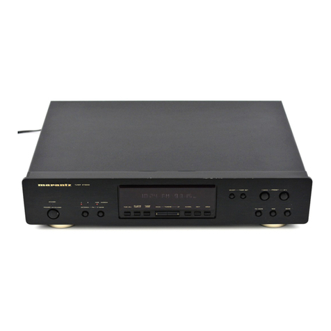
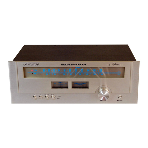
  9. Marantz ST500 User manual

Marantz ST500 User manual

SERVICE
MANUAL
Ay C4
LN
MARANTZ
DESIGN
AND
SERVICE
Using
superior
design
and
selected
high
grade
components,
MARANTZ
Company
has
created
the
ultimate
in
stereo
sound.
Only
original
MARANTZ
parts
can
insure
that
your
MARANTZ
product
will
continue
to
perform
to
the
specifications
for
which
it
is
famous.
Parts
for
your
MARANTZ
stereo
are
generally
available
within
72
hours
throughout
the
nation
via
a
toll-free
line
to
our
National
Parts
Depot
in
California.
The
sales
professionals
who
take
your
call
immediately
refer
to
their
own
desk
top
com-
puter
terminal
and
can
quickly
determine
the
availability
and
price
information
you
require.
If
for
some
reason,
your
order
should
exceed
our
available
stock,
we
usually
can
instantly
provide
an
alternate
replacement
part
or
current
delivery
infor-
mation.
When
the
order
is
placed
and
confirmed,
the
computer
simultaneously
generates
“hard
copy”
orders
at
the
distribution
center.
As
hard
copies
come
directly
from
the
computer
to
the
national
parts
depot,
your
requested
stock
is
assembled
and
prepared
for
shipment
and
placed
on
the
first
available
carrier
for
delivery
to
you.
ORDERING
PARTS
Phone
orders
will
eliminate
mail
delays,
and
we
encourage
the
use
of
this
method.
If
you
order
by
mail,
use
MARANTZ
parts
order
forms
which
are
available
from
our
National
Parts
Depot
located
at
the
following
address:
SUPERSCOPE
NATIONAL
PARTS
DEPARTMENT
20525
Nordhoff
Street
Chatsworth,
California
91311
Phone:
1-800-423-5108
1-213-998-9333
The
following
information
must
be
supplied
to
eliminate
delays
in
processing
your
order:
.
Complete
address.
.
Complete
part
numbers.
.
Complete
description
of
parts.
.
Model
number
for
which
part
is
required
(indicate
MARANTZ).
.
Account
number
(for
account
customers
only).
OhWN
=
Direct
consumers
will
be
provided
with
the
current
retail
prive
quotation
on
available
parts
in
order
to
advise
them
of
the
cost
of
the
parts
and
shipping.
OVERSEAS
PARTS
ORDERING
Parts
may
also
be
ordered
from
the
following
overseas
addresses:
CANADA
AUSTRALIA
JAPAN
Marantz
Europe,
S.A.
Superscope
(Australasia)
Pty.,
Ltd.
Marantz
GmbH
3710
Nashua
Drive
32
Cross
Street
(P.O.
Box
604)
3622
Kamitsuruma
Mississauga
Brookvale
2100
N.S.W.
Sagamihara
Shi
Ontario,
Canada
L4V1M5
Australia
Kanagawa,
Japan
EUROPE
Superscope
Europe,
S.A.
Marantz
France
Marantz
Audio
U.K.
Ltd.
Superscope
GmbH
Avenue
Leopold
Il,
2
Rue
Louis
Armand
9
London
Road,
203
Max-Planck-Strasse
22
7120
Peronnes-Lez-Binche
92600
Asnieres
Staines
D-6072
Dreieich
1
Belgium
Hauts-de-Seine
Middlesex
West
Germany
France
England
All
of
the
above
locations
are
fully
equipped
to
take
care
of
your
total
service
needs.
Because
various
countries
have
differing
?
configuration
requirements,
it
is
necessary
that
you
contact
the
service
facility
in
your
particular
country.
In
the
event
that
there
is
no
service
location
listed
for
your
country,
please
contact
the
nearest
facility
for
the
necessary
assistance.
BRnem
Been
watz.
We
sound
better
TABLE
OF
CONTENTS
SECTION
PAGE
De
ANT
RO
DUC
ON
ies
oie
See
A
aw
aac
ae
aan
Sa
aa
a
ard
ae
a
OG
AS
Cw
ea
ae
1
2.
PW.
BOARDS
scsi
h
cise
ea
hae
g
SRW
ce
he
a
See
hs
Seah
OG
ols
Ge
woe
Wack
eR
ee
2
3.
TEST
EQUIPMENT
REQUIRED
FOR
SERVICING
...
1...
ccc
ene
re
eens
2
4,
TUNER
ALIGNMENT
PROCEDURES.....
1.2...
cc
cece
cece
cere
e
eee
eee
ete
2~5
5.
VOLTAGE
CONVERSION...
0...
ccc
cc
eee
eee
ene
eee
eee
eee
eee
e
neta
6
6.
FREQUENCY
SYNTHESIZER
RADIO
TUNING
SYSTEM
.....
0...
.
cece
eee
ee
eee
eens
7~17
7,
DIAGRAM
AND
COMPONENT
LOCATIONS
..............
ccc
cee
ce
cece
nee
eeeeeeeeenas
18
~
25
8.
FUNCTIONAL
BLOCK
DIAGRAM
.....
1...
0.
cc
eee
eee
nee
eeees
26
9,
EXPLODED
VIEW
AND
PARTS
LIST...
1.2...
ce
cc
ccc ete
ee
eee
eee
ee
nees
27
~
32
1D
ELECTRICAL
PARTS
LIST
63
ve
sce
eee
ieee
oie
PREG
eS
i
ca
Ca
hd
VR
VERE omer
ea
ae
33
~
37
11.
TECHNICAL
SPECIFICATIONS.
.........
cece
cee
eee
ete
tenet
eee
nes
39,
40
12.
SCHEMATIC
DIAGRAM
MODEL
ST500
AM/FM
STEREOPHONIC
TUNER
SFOS
G00
1.
INTRODUCTION
This
service
manual
was
prepared
for
use
by
Authorized
Warranty
Stations
and
contains
service
information
for
Marantz
Model
ST500
AM/FM
Stereophonic
Tuner.
Servicing
information
and
voltage
data
included
in
this
manual
are
intended
for
use
by
the
knowledgeable
and
experienced
technician
only.
All
instructions
should
be
read
carefully.
No
attempt
should
be
made
to
proceed
without
a
good
understanding
of
the
operations
in
the
tuner.
The
parts
list
furnishes
information
by
which
replacement
parts
may
be
ordered
from
the
Marantz
Company.
A
simple
description
is
included
for
parts
which
can
usually
be
obtained
through
local
suppliers.
NOTE
ON
SAFETY:
&
computer
Sim
tuner:
selector
.
ee
re
Tartine
SCaee
co
power
4
2.
P.W.
BOARDS
As
can
be
seen
from
the
circuit
diagram,
the
chassis
of
Model
ST500
consists
of
the
following
units.
Each
unit
mounted
on
a
printed
circuit
board
is
described
within
the
square
enclosed
by
a
bold
dotted
line
on
the
circuit
dia-
gram.
1.
Tuner
&
Synthesizer
. .
.
mounted
on
P.W.
Board
P100
2..Noise
Amplifier.......
mounted
on
P.W.
Board
PBOO
3.
Display
Ass’y........
mounted
on
P.W.
Beard
P900
4.
DE-Emphasis
Switch
...
mounted
on
P.W.
Board
PCOO
5.
Scan
Step...........
mounted
on
P.W.
Board
PC50
6.
FUSC:)
bcc
eee
eee
mounted
on
P.W.
Beard
PPOO
7.
Function
Switch......
mounted
on
P.W.
Beard
PSOO
8.
Mode
Switch
........
mounted
on
P.W.
Board
PT00
9.
Preset
Switch........
mounted
on
P.W.
Board
PU0O
THE
PARTS
MARKED
WITH
A
ARE
IMPORTANT
PARTS
ON
THE
SAFETY.
PLEASE
USE
THE
PARTS
HAVING
THE
DESIGNATED
PARTS
NUMBERS
WITHOUT
FAIL.
FTZ
REGULATION
Instruction
for
the
use
in
the
range
other
than
specified
in
FTZ
codes.
Achtung
fiir
die
Leute,
die
in
dem
Gebiet
wohnen,
wo
die
FTZ-Bestimmungen
vorherrschend
sind.
Sollte
des
Geradt
auch
fiir
Frequenzen
auszerhab
des
in
den
FTZ-Bestimmungen
angegebenen
Bereiches
«mpfange-
bereit
sein,
bitten
wir,
den
Bereich
durch
Nachzellen
des
Kernes
in
der
Oszillatorspule
(in
der
Abbildung
nit
“FTZ”
gekennzeichnet)
so
zu
korrigieren,
dass
er
den
Betimmun-
gen
entspricht.
3.
TEST
EQUIPMENT
REQUIRED
FOR
SERVICING
This
table
lists
the
test
equipment
required
for
servicing
the
Model
ST500
Tuner.
Use
Signal
source
for
AM
alignment
[Trem
|___
Manufacturer
and
Model
No,
AM
Signal
Generator
Test
Loop
Use
with
AM
Signal
Generator
FM
Signal
Generator
Signal
source
for
FM
alignment
ane
St
e
ti
li
tand
MPX
Signal
Generator
Sound
Technology
Mode!
1000A
ereo
separation
alignment
and
trouble
shooting
Distortion
Analyzer
Distortion
measurements
Audio
Oscillator
‘|
Sound
Technology
Model
1700A
Sinewave
and
squarewave
signal
source
AC
VTVM
Voltage
measurements
(AC)
Tektronix
Model
T93
;
Oscilloscope
isaac
pede
2
Waveform
analysis
and
trouble
shooting
Philips
Model
3232
MPX
Oscillator
adjustment
(VCO)
Trouble
shooting
Frequency
Counter
Circuit
Tester
Fluke
Model
8000
“‘Digital’’
Simpson
Model
313,
Triplet
Model
801
AC
Wattmeter
Simpson
Model
1379
Monitors
primary
power
to
tuner
Line
Voltmeter
Simpson
Model
1359
Monitors
potential
of
primary
power
to
tuner
.
Superior
Electronic
Co.,
‘ :
Variable
Autotransformer
Powerstat
Model
116B-10A
Adjusts
level
of
primary
power
to
tuner
DC
VTVM
Voltage
measurements
(DC)
4.
TUNER
ALIGNMENT
PROCEDURES
A
dummy
resistor
of
47
kohms
must
be
connected
across
the
tuner
output
terminals
before
alignment.
4.1
FM
Alignment
Procedures
(Selector
switch
in
the
“FM”
position,
mode/tuning
switch
in
the
Mono/Manual
Position.)
1.
FM
Local
Oscillator
Alignment
Indicator
Connection
Signal
Frequency
Set
the
Digital.
Readout
Frequency
to
Signal
Source
Connection
Repeat
steps
1
and
2
107.90
MHz
C117
for
201V
DC
voltmeter
in
30V
and
3V
range
to
J505
88.10
MHz
L106
for
3.0)
3
|
;
|
F
2.
FM
RF
Alignment
Signal
Source
Connection
Signal
tndicator
Set the
Digital
Frequency
Connection
Readout
Frequency
RF
generator
to
FM
antenna
terminal
through
matching
network
(300
ohms,
balanced)
Maintain
RF
level
below
limit.
C101,
C107,
C110
for
106.10
MHz
106.10
MHz
maximum
output
and
VTVM
to
Lor
minimum
distortion.
R
channel
output
(3102)
L101,
L102,
L103
for
90.10
MHz
90.10
MHz
maximum
output
and
minimum
distortion.
Repeat
steps
1
and
2.
RF
generator
to
FM
antenna
terminals
through
matching
network
(300
ohms,
balanced)
Maintain
RF
fevel
below
limit.
RF
generator
1mV
output
to
FM
antenna
terminals
through
matching
network.
(300
ohm,
balanced)
RF
generator
1mV
output
to
FM
antenna
terminals
through
matching
network.
(300
ohms,
balanced)
RF
generator
1mV
output
to
FM
7
antenna
terminals
through
matching
network.
(300
ohms,
balanced)
VTVM
to
LorR
98.10
MHz
channel
output
98.10
MHz
(J102)
L105
for
maximum
output
and
minimum
distortion.
“0”
center
meter
or
DG
current
98.10
MHz
meter
in
100uA
98.10
MHz
range
between
J201
and
J202
L202
primary
core
so
that
the
meter
indicates
its
center
or
may
read
“Q",
{F
Band
switch
"“Wide’’.
202
secondary
core
for
minimum
distortion.
IF
Band
switch
“Narrow”.
L201
core
for
minimum
distortion.
Distortion
meter
to
L
or
R
channel
98.10
MHz
output
(J102)
98.10
MHz
RTO1
so
that
signal
strength
Led
may
light
5
points.
98.10
MHz
98.10
MHz
ee
RF
generator
to
FM
antenna
terminals
through
matching
network
(300
ohms,
balanced)
with
the
RF
signal
level
of
that
the
sigral
strength
LED
may
light
3
points
.at
IF
band
switch
“Wide"’.
1F
Band
switch
“Narrow”.
R215
so
that
signal
strength
Led
may
light
3
points.
98.10
MHz
98.10
MHz
4.2
Muting
Circuit
Alignment
~
(FM
stopping
level
of
scanning.
FM
stereo
indicator
threshold
level.)
Signal
Source
Connection
Signal
Frequency
Indicator
Connection
Set
the
Digital
Readout
Frequency
Adjust:
RF
generator
12.5uV
output
to
FM
antenna
terminal
through
matching
network
(300
ohm,
balanced)
98.10
MHz
4.3
Multiplex
Alignment
Procedures
(Selector
switch
in
the
“FM”
position.
Mode/Tuning
switch
in
the
Stereo/Auto
position.)
Signal
Source
Connection
Signal
Frequency
VTVM
to
RorLl
channel
output
(J102)
98.10
MHz
Set
the
Digital
Readout
Frequency
indicator
Connection
R229
for
12.5uV
threshold
level
(setting
to
Auto
position
of
“Mode”
switch)
Adjust:
RF
generator
to
FM
antenna
terminals
through
matching
network
(300
ohms,
balanced)
with
1mV
FM
stereo
simulator
RF
level
and
100%
modulation
(Pilot
9%)
RF
generator
to
FM
antenna
terminals
through
matching
network
(300
ohms,
balanced)
with
1mV
FM
stereo
simulator
RF
level
and
Pilot
9%
modulation.
4.4
AM
Alignment
Procedures
No
modulation
Stereo
left
(1,000
Hz)
Stereo
right
(1,000
Hz)
Pilot
only
Frequency
counter
to
(J301)
VTVM
to
right
channel
output
(J102)
98.10
MHz
VTVM
to
left
channel
output
terminal
(J102)
Repeat
steps
2
and
3.
VTVM
to
right
and
left
channel
output
(J102)
(Selector
switch
in
the
“AM”
position.
Mode/Tuning
switch
in
the
Mono/Manual!
position.)
1.
AM
Local
Oscillator
Alignment
(Scan
step
selector
switch
(SC51)
in
the
“10
kHz”
position.)
Signal
Source
Connection
Signal
Frequency
Set
the
Digital
Readout
Frequency
Indicator
Connection
DC
voltmeter
in
1,610
kHz
|
30V
and
3V
range
to
(J505)
530
kHz
Repeat
steps
1
and
2.
R303
so
that
Frequency
may
precisely
read
76
kHz
1F
Band
switch
’’Wide”
RSO5.
IF
Band
switch
‘‘Narrow”
RS04.
For
same
separation
in
‘both
channels,
R306
so
that
minimum
output
should
be
the
sarne
in
both
channels.
CA10
for
23V
LAO2
for
2.0V
2.
AM
IF
Alignment
Signal
Source
Connection
Signal
Frequency
Indicator
Connection
Set
the
Digital
Readout
Frequency
Adjust:
Sweep
generator
to
(RAOS)
3.
AMRF
Alignment
4.
AM
Stopping
Level
of
Scanning
(Mode/Tuning
switch
in
the
“Stereo/Auto”
Position.)
Signal
Source
Connection
450
kHz
marker
Signal
Frequency
Oscilloscope
to
(JAO5)
Indicator
Connection
Quiet
point
on
band
Set
the
Digital
—
Readout
Frequency
LAO3
&
LAO4
for
maximum
and
symmetric
response
Adjust:
Apply
the
signal
to
the
AM
bar
antenna
from
the
RF
generator
using
the
test
loop.
As
per
the
Figure
1.
1,400
kHz
600
kHz
VTVM
to
Lor
R
channel
output
(J102)
1,400
kHz
600
kHz
|
CAO2
for
maximum
output
L051
for
maximum
output
Apply
the
signal
to
the
AM
bar
antenna
from
the
RF
generator
using
the
test
loop.
As
per
the
Figure
1.
(with
3mV/m)
Signal
Source
Connection
Repeat
steps
1
and
2
as
necessary
to
obtain
maximum
sensitivity.
1,000
kHz
Signal
Frequency
Indicator
Connection
1,000
kHz
Set
the
Digital
L
Readout
Frequency
RSO6
so
that
signal
strength
LED
may
light
4
points.
Apply
the
signal
to
the
AM
bar
antenna
from
the
RF
generator
using
the
test
loop.
As
per
the
Figure
1.
(with
600uV/m)
1,000
kHz
=
VTVM
to
L
or
R
channel
output
(J102)
Test
Loop
60cm
1,000
kHz
AM
Bar
Antenna
Figure
1.
Application
of
AM
Signal
RA18
for
600;V
threshold
level
5.
VOLTAGE
CONVERSION
e
EUROPEAN
MODEL
ONLY
To
convert
the
unit
to
a
different
power
source
voltage,
change
the
position
as
illustrated
in
the
drawing
below.
CAUTION:
DISCONNECT
POWER
SUPPLY
CORD
FROM
AC
OUTLET
BEFORE
CONVERTING
VOLTAGE.
DO
NOT
DISASSEMBLE
THE
VOLTAGE
SELECTOR
ABSOLUTELY.
(T)
(A)
Versions
(N)
Version
—
(P)
Version
Figure
2.
Voltage
Conversion
Chart
>
6.
FREQUENCY
SYNTHESIZER
RADIO
TUNING
SYSTEM
[1]
Construction
of
Synthesizer
System
This
frequency
synthesizer
is
composed
of
a
microcomputer
(MN1400SJ),
PLL
LS!
(MN6142),
CMOS
RAM
(MN1203),
prescaler
(uPB551C),
low
pass
filter,
crystals
and
fluorescent
indicating
tubes,
as
shown
in
Figure
1.
PLL
MN
6142
PRESCALER
yPBSSIC
MICROCOMPUTER
MN
14008J
CMOS
RAM
MN
1203
INDICATOR
KEY
BOARD
Figure
1
[2]
Microcomputer
MN1400SJ
[2]-1.
Terminal
Connections
[2]-2.
Block
Diagram
TOP
VIEW
INSTRUCTION
PLA
rE)
STACK
2
LEVEL
t
2
3
4
5
6
7
8
9
J
Im
eof
MN
1400
SJ
g
Figure
2
C:
COINCIDENCE
DETECTOR
G:
GATE
L:
LATCH
S:
SYNCHRONIZING
CIRCUIT
Figure
3
[2]
-3.
Specifications
Maximum
Ratings
Electrical
Characteristics
(Ta
=
25°C)
(Ta
=
25°C)
Condition
Al0~AI3,
BIO~BI3
SNSO,
SNS1
N-Channel
(C,D,E.
Port)
LOCOS
E/D
MOS
|
!on
(aV)
a
MN1400
|
““4.Bit
+
1Chip
|
(C,D,E.
Port)
ee
noY
Microcomputers
ou
(aV)
.
(C,D,E.
Port)
:
CO0~CO11,
Voo
=
5V
;
atl
A
Jou
=
-30uA
SYNC,
EOS-EOS,
Jas
=8v
|
DOPS,
RAO~RA10
|
y=
1
00uA
J
Operating
Condition
Von
=
5V
:
(Ta
=
25°C)
lo.
=
2mMA
:
=
’
Ci
|
Vino
=
SV,
Vi
=
2V
5
‘
[2]
-4.
Functions
of
Terminals
Memory
chip
enabling
output
CO3
31
|
DOO
©
|
Fasano
pret
ouput
cor
|
anddigit
|
es
|
Keymodeswtchinput
iP
TST
Alt
Key
mode
switch
input
yd
28
Et
Kev
mode
atch
outnut
|
PY
£00
|
memory
PLL
res
nc
ee
ot
Se
8
Segment
output:
f
‘Frequency-division
ratio
preset
output
Q
2)
ron)
€
Segment
output:
@
Frequency-division
ratio
preset
output
Oo;,o|o
“|
oO]
oO
2/aQ
R\k
Segment
output:
g
Frequency-division
ratio
preset
output
=a
/f{—a3/
—
=
«©
|
co
~~
>
Ld
i)
(3]
PLL
LSI
MN6142
(3]-1.
Terminal
Connections
(3]
-2.
Specifications
Absolute
maximum
ratings
Rating
Unit
|
Remarks
Power
supply
voltage
Vop
sf
~0.3~+10
Power
consumption
P+(MAX)
50
Input
voltage
VIN
~
|=0.3~Vppt0.3
|
Output
voltage
Vout
*
-0.3~Vppt0.3
Operating
temperature
Vopt
-20~+70
Storage
temperature
Tstg
-55~+100
Figure
4,
(3]
-3.
Block
Diagram
12-BIT
PROGRAMMABLE
COUNTER
PROGRAMMABLE
FREQU
DIVIDER
INPUT
@
Pi
TT
TT
TILITI
ttl
(4)
Po
FREQUENCY
DIVIDING
©:
7
PHASE
@pro
RATIO
SE
pe
COMPARATOR
ope
input
|
(4)
PHASE
COMPAR
ATOR
@)P3
OUTPUT
OSCILLATOR
CIRCUIT
ost!
x'tal
LS2MHz
CJ
osc2
3-BIT
PROGRAMMABLE
REFERENCE
FREQUENCY
DIVIDER
CIRCUIT
GI
G2 G3
G4
G5
34
+H
fel
°
@ao
cro
(vss
vo
co
(ci
(ez
OSCILLATOR
SYNC
SIGNAL
LATCH
GROUP
INPUT
OUTPUT
OUTPUT
Figure
5.
Descriptions
Power
supply,
+5V
Frequency
dividing
ratio
preset
code
input
Programable
frequency
divider
input
Frequency
dividing
ratio
preset
code
input
Frequency
dividing
ratio
preset
code
input
Oscillator
Oscillator
Oscillator
output,
11.52
MHz
Sync
signal
output,
360
kHz
Phase
comparator
output
Latch
group
select
input
Latch
group
select
input
Latch
group
select
input
Frequency
dividing
ratio
preset
code
input
Load
signal
terminal
for
frequency
dividing
ratio
preset
code
input
latch
circuit
Ground
[41
CMOS
RAM
MN1203
(4]
-1.
Terminal
Connection
[4]
-2.
Specifications
Absolute
maximum
ratings
Remarks
16]
DO
3
Power
supply
voltage
Vss=0V
15]
DO
2
Input
terminal
voltage
Vss=0V
4]
00
|
Output
terminal
voltage
|
Vout
ie
cE
HO]
ADS
19]
ADL
Figure
6.
10
[4]
-3.
Block
Diagram
3.
Functional
block
diagram
Figure
7.
iy
COINCIDENCE
CIRCUIT
LATCH
2
A
ss
ADDRESS
DDRE
ig-=
MEMORY
CELL
ARRAY
ADDRESS
4x64
BITS
LATCH
|
Lowes)
4BITS
{4]
-4.
Functions
of
terminals
11
Descriptions
Power
supply,
+5V
Chip
select
input
Chip
select
input
Ground
Data/address
input
Data/address
input
Data/address
input
Data/address
input
ADL
Address
latch
data
input
ADS
Address
latch
select
input
CE
28a
|
9
|
|
10
|
p41
|
Chip
enable
input
[aw
|
wits
to
oar
|
13
|
ae
|
15
|
Eom
[p00
[atau
id
ee
[p02
[ata
output
(0s
[ate
output
{5]
PRESCALER
uPB551C
[5]
-1.
Terminal
Connections
Figure
8.
[5]
-2.
Specifications
Absolute
maximum
ratings
(Ta
=
25°C)
Rating
'-0.5
~
+6.0
-0.5~Vec
15
+125
-55
~
+125
Item
Conditions
Power
supply
current
Vec
=
5.0V
Out
terminal,
1g
=-40uA
Low
level
output
voltage
Out
terminal,
lo
=
1.0mA
M3
terminal
*1
Low
level
input
voltage
M3
terminal
*2
Input
voltage
Vin
IN
terminal
Response
frequency
IN
terminal,
1/10,
1/11
frequency
dividing
*3
Response
frequency
[5]-3.
Block
Diagram
1/2
IN
(2)
AMPLIFIER
SnnER
Vec
:
POWER
SUPPLY
“’#'
IN
:
SIGNAL
INPUT
CH
:
CHECK
TERMINAL
GND
:
GROUND
OUT
:
DIVIDED
FREQUEIC
Y
OUTPUT
:
M3-M1:
FREQUENCY
DIVIUMIG
RATIO
i
:
SETTING
CMOS
LEVEL
TRANSLATOR
1710,
It
DIVIDER
M3
CH
vec
GND
——
Figure
9.
12
{6]
Principles
of
Operation
of
PLL
Synthesizer
Tuning
System
This
synthesizer
system
incorporates
a
PLL
circuit
and
a
microcomputer
to
electronically
select
radio
stations
by
varying
the
capacity
of
a
varactor
diode,
eliminating
the
need
for
a
mechanical
variable
condenser.
The
basic
operation
of
the
system
is
illustrated
in
Fig.
10.
When
a
reserve
voltage
is
applied
to
the
varactor
diode,
the
junction
capacity
of
the
diode
is
varied
which
in
turn
varies
the
tank
tuning
frequency
and
hence
the
antenna
circuit,
RE
amplifier
and
local
oscillator
circuit
are
tuned
to
the
desired
radio
frequency.
In
FM
tuning,
the
local
oscillator
frequency
fL
is
divided
by
20
by
the
prescaler,
since
it
is
as
high
as
yy
98.8-118.6
MHz
(or
Sey
98.2-118.7
MHz).
The
divided
frequency
is
then
applied
to
the
1/N
programmable
counter
where
it
is
further
divided
by
N.
The
divided
signal
(fL’)
is
phase-
compared
with
the
reference
signal
(fr),
which
the
crystal
oscillator
frequency
(11.52
MHz)
is
count
down
by
the
reference
frequency
divider.
{f
there
is
a
difference
in
frequency
or
phase
between
the
two
signals,
an
error
output(er)
corresponding
to
the
dif-
ference
is
produced.
The
error
output
is
a
pulse
signal
and
its
DC
component
is
picked
up
by
the
LPF
in
the
next
stage.
The
DC
com-
ponent
is
fed
back
to
the
varactor
diode
to
vary
the
local
oscillator
frequency.
13
When
the
local
oscillator
frequency
is
varied
and
‘‘fr’’
and
“€L'"'
are
equal,
the
phase
sync
loop
is
locked.
fL’
fL
fL/20N
=
fr
20Nfr
By
changing
the
value
of
N
(an
integer)
fed
from
the
micro-
computer
to
the
1/N
programmable
counter,
the
local
oscillator
frequency
can
be
varied
in
20fr
steps.
When
tuning
FM
in
200
kHz
steps,
the
value
of
N
=
2N’
(N’:
integer)
is
fed
from
the
microcomputer.
Proper
tracking
adjustment
between
the
tuning
circuit
for
the
antenna
and
RF
amplifier
and
the
local
oscillator
tuning
circuit
enables
reception
of
the
desired
station.
The
microcomputer
programs
the
relationship
between
the
receiving
mode,
intermediate
frequency
and
the
value
of
N
and
feeds
the
data
of
the
receiving
frequency
via
the
driver
to
indicate
the
tuned
frequency
on
the
fluorescent
tube
indicator.
ve
FM:1/36
AM:1/10
sv
98.8-118.6
eee
494—-5.93
-
Ne
1/20
FM:
1/18
98.2-118.7
———>
4.91
—
5.935
AM:1/9
11.52MHz
f
oc
'
=
FM:
5kHz
BYAeON
i
oat
!
Fm:
ANTENNA
FM:
1/988-I/1186
|
FM:
1/1964-1/2374
CIRCUIT
5
ace
RE
AMPLIFIER
AM:
1/98-1/203
|
AM:
1/109-1/228
CIRCUIT
:
AM:
ANTENNA
1/N
PROGRAMMABLE
COUNTER
CIRCUIT
j
<<
oe
Cl,
C2:
FREQUENCY—DIVISION
RATIO
SETTING
SIGNAL
MN
1400
SJ
Figure
10.
incecnadls®
Local
oscillator
frequency
Number
of
Shas
compester
ving
f
Somnatep
Riecenyind
sreguesney
frequency
channels
reference
frequency
FM:
200KHz
88.1MHz
~
107.9MHz
10.7MHz
98.8MHz
~
118.6MHz
AM:
10KHz
530KHz
~
1,610KHz
450KHz
980KHz
~
2,060KHz
FM:
SOKHz
87.50MHz
~
108.00MHz
10.7MHz
98.2MHz
~
118.7MHz
AM:
9KHz
531KHz
~
1,602KHz
*
450KHz
981KHz
~
2,052KHz
Mode
Setting
and
Contro!
Key
Connections
+5V
MANUA\
x
fe)
A
©
auto
MI
FMSOkH;
AM
Sktag
SCAN
STEP
ca:
<
i
i
aranae
°
eM
DOWN
M5
M2
Al3
AlL2
AI!
ALO
MN
1400
SJ
MW:
Memory
write
AUTO/MANUAL:
Scan
AUTO/MANUAL
select
switch.
*
Memory
write
is
possible
with
key
input.
*
AUTO........
Automatic
scan
with
up/down
key
input.
*
Memory
write
mode
is
retained
for
5
seconds
after
key
*
MANUAL
...
Manual
scan
with
up/down
key
input.
input
is
turned
ON.
AM/FM:
AM/FM
select
switch
M1-M7:
Memory
address
*
Selects
AM
and
FM
bands.
*
Received
station
is
stored
in
memory
by
key
input
in
*
Calls
the
last
channel
of
the
selected
band.
memory
write
mode.
*Station
frequency
stored
in
memory
is
called
in
mode
CS:
Chip
select
switch
other
than
“memory
write”
*
Display
goes
off
at
ON
position.
*
Control
key
input
is
inhibited
at
the
same
time.
UP,
DOWN:
Up/Down
scan
SCAN
STEP:
Channel
space
and
frequency
select
switch.
Mode
switch
in
AUTO:
Scanned
at
about
110
msec/ch
*
AM
10K:
10kHz
space
530kHz
-
1,610
kHz
intervals.
FM
200K:
200kHz
space
88.1MHz
-
107.9MHz
Mode
switch
in
MANUAL:
a)
Step
scan
by
channel.
*
AMOK:
QkHz
space
531kHz
-
1,602kHz
b)
Scanned
at
about
90
msec/ch
FM
50K:
50kHz
space
87.50MHz
-
108Mhz
one
second
after
continuous
key
input.
Switches
other
than
SCAN
STEP
are
transistor
switches
and
used
for
remote
control
capability.
Scan
stop:
AUTO
....eeeeeeeees
Activated
by
squelch
signal
(receive
signal).
MANUAL
........
Activated
by
key
input
OFF.
4,
23-25
DC
IN
14-17
15
Indicator
Dynamic
Lighting
Timing
Chart
The
indicator
employs
fluorescent
tubes
for
dynamic
light-
ing.
Dynamic
lighting
timing
chart
MICRO—
“an
Se
ae
ee
COMPUTER
INDICATOR
OUTPUT
GRID
’
GS2
Gs
G4
G3
G2
Gi
GS
D5
—
GS2
D4
—
G5
a
Ye
=I
tala
12
tesa
ek
le
de
|°2!
lez]
ao
|
ica
ey
J
arene
eae
2
noe
Oe
eee
FM
STEREO
KAVINAL
mA
5
a
UT
a2
i
—
DIGIT
D3
—_
G4
SIGNAL
Oo
rr)
—
i)
oe
ee
8
D2
=
G3
Tareas
|
DI
=
G2
DO
-—Gl,
GSI
ee
(ike
Cee
ee
ne
Eto
see
Ue
ee
ee
ees
i
eee
oes
ee
ee
Soe
esllh
le
ee
eee
a
en
taf\
L[oa
tal\
/]bs
Pa
oi
Tcsee
eel
e
Mee
bat
ae
s
ees
ie
eee:
SEGMENT
SIGNAL
aQ
~~
0
a
ao
F
A
=
DISPLAY
BAND
FM
——_1
cre
ae
SIGNAL
AM
DISPLAY
POINT
DISPLAY
FM
STEREO
_]
-
=a
FM
STEREO
DISPLAY
*
In
the
above
timing
chart,
the
display
lights
on
FM
STEREO,
ME
and
FM
108.00
MHz.
*
For
the
indication
of
minimum
digit
(G1),
the
segments
a1,
c1,
d1
and
f1
are
always
lighted,
the
letter
5
is
lighted
by
the
signal
g,
and
the
figure
O
is
lighted
by
signals
b1
&
e1
fed
by
Q902
&
Q903
when
the
signal
g
is
low
level.
*
Z
7.
DIAGRAM
AND
COMPONENT
LOCATIONS
7.
1
Tuner
and
Synthesizer
Assembly
(P100)
Schematic
Diagram
and
Component
Locations-
——?
—<—_—2
<a
Ge
Sos
3308
220
/50v
Laor
RED
ty
aot
ORG
-
sAOZ
BLU
JA03
Hot
|
.
1H
nee
@)—
O-~)-6-@
ISIV
65V
63V
6.5V
6.5V
26
47V
OY
his,
ened
se
ee
&
aA
wa
65v
ah
i6v
ae
4
2
O25 naa
.
Sf
8
ie
R540
100K
9
R530~
Poa
g
&
Na
|
|
eee
)
sti
cso1
aor
1501
1OpH
C503
og
730
‘aoe
woz
1803

Other Marantz Tuner manuals

Marantz ST-54 User manual

Marantz

Marantz ST-54 User manual

Marantz AV7005 Quick start guide

Marantz

Marantz AV7005 Quick start guide

Marantz AV8801 Quick start guide

Marantz

Marantz AV8801 Quick start guide

Marantz ST7001/N1S User manual

Marantz

Marantz ST7001/N1S User manual

Marantz ST6000 User manual

Marantz

Marantz ST6000 User manual
Marantz AV7702mkII User manual

Marantz

Marantz AV7702mkII User manual

Marantz AV7702mkg User manual

Marantz

Marantz AV7702mkg User manual

Marantz AV7005 Assembly instructions

Marantz

Marantz AV7005 Assembly instructions

Marantz ST7001 User manual

Marantz

Marantz ST7001 User manual

Marantz ST4000 User manual

Marantz

Marantz ST4000 User manual

Marantz AV7702mkII User manual

Marantz

Marantz AV7702mkII User manual

Marantz AV9000 User manual

Marantz

Marantz AV9000 User manual

Marantz 10B User manual

Marantz

Marantz 10B User manual

Marantz AV8802 User manual

Marantz

Marantz AV8802 User manual

Marantz AV8805 User manual

Marantz

Marantz AV8805 User manual

Marantz AV8801 User manual

Marantz

Marantz AV8801 User manual

Marantz ST-17 User manual

Marantz

Marantz ST-17 User manual
Marantz 74ST48/01B User manual

Marantz

Marantz 74ST48/01B User manual

Marantz ST7001 User manual

Marantz

Marantz ST7001 User manual

Marantz ST6000 User manual

Marantz

Marantz ST6000 User manual

Marantz ST7001 Installation and operating instructions
Marantz

Marantz ST7001 Installation and operating instructions

Marantz 110 User manual

Marantz

Marantz 110 User manual

Marantz AV8802A User manual

Marantz

Marantz AV8802A User manual

Marantz ST6003 User manual

Marantz

Marantz ST6003 User manual

Popular Tuner manuals by other brands

Johansson 5400 user manual

Johansson

Johansson 5400 user manual

Seiko STX5 instruction manual

Seiko

Seiko STX5 instruction manual

Nuvo NV-T2FAM-EX installation guide

Nuvo

Nuvo NV-T2FAM-EX installation guide

Korg Sledgehammer Pro owner's manual

Korg

Korg Sledgehammer Pro owner's manual

Enseo ICS-SP30 user guide

Enseo

Enseo ICS-SP30 user guide

Bogen DST1 user manual

Bogen

Bogen DST1 user manual

NEC DS1-TM01 user manual

NEC

NEC DS1-TM01 user manual

Toa Scout WT-4810 operating instructions

Toa

Toa Scout WT-4810 operating instructions

Matsushita Electric TY-FB8TA Service manual

Matsushita Electric

Matsushita Electric TY-FB8TA Service manual

Sirius Satellite Radio SiriusCONNECT SIR-CL3 installation guide

Sirius Satellite Radio

Sirius Satellite Radio SiriusCONNECT SIR-CL3 installation guide

DRAKE MN-2000 instruction manual

DRAKE

DRAKE MN-2000 instruction manual

Kenwood KTC-H2A1 - Here2Anywhere Sirius Radio instruction manual

Kenwood

Kenwood KTC-H2A1 - Here2Anywhere Sirius Radio instruction manual

Integra TV Speaker Base Service manual

Integra

Integra TV Speaker Base Service manual

Hama DIT2105SBTX operating instructions

Hama

Hama DIT2105SBTX operating instructions

Arcam DT91 Handbook

Arcam

Arcam DT91 Handbook

Denon TU-6.5 operating instructions

Denon

Denon TU-6.5 operating instructions

Rotel RT-1082 owner's manual

Rotel

Rotel RT-1082 owner's manual

Ibanez PU10 user manual

Ibanez

Ibanez PU10 user manual

manuals.online logo
manuals.online logoBrands
  • About & Mission
  • Contact us
  • Privacy Policy
  • Terms and Conditions

Copyright 2025 Manuals.Online. All Rights Reserved.