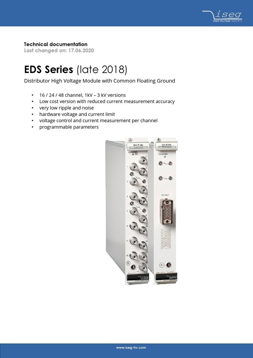
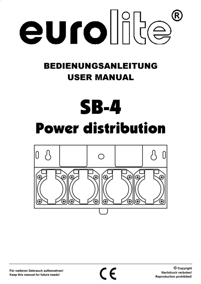
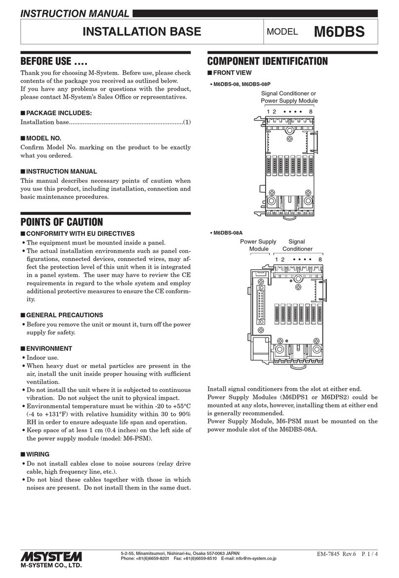
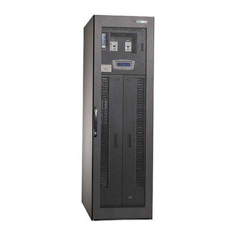
LDR PDU6M User manual

20106260 PDU6M, DMX512+ RDM
power distribution unit
istruzioni per l'uso
operating instructions
Bedienungsanleitung
instrucciones de manejo
mode d'emploi
gebruiksaanwijzing
Luci della Ribalta srl, Via Berna 14, 46042 Castel Goffredo mn Italy. tel +39 0376 771 777 - fax +39 0376 772 140 - email [email protected]

PDU6M MANUAL V0.1
ENGLISH TABLE OF CONTENTS
ITALIANO INDICE
Important safety norms ………………………………………………........................ page 2
1. Check box content……………………………………………………….………. page 3
2. Weight and dimensions………………………………………………........... page 3
3. Features ……............................................…………………………….… page 4
4. Identifying the parts …………………………………………………………….. page 5
5. Description and functions of the parts………………………………….. page 6
6. Installation .............................................…………………………..…… page 8
7. Operation .……… …………………………………………………………….….…. page 8
7.1 Connect to power page 8
7.2 Select the working mode page 8
7.3 Xpress RDM system connection diagram page 9
7.4 Input signal connection page 9
7.5 Power and output signal connection page 10
7.6 Controllable units page 10
7.7 Scroller control cable page 11
8. Trouble shooting ..................…………….…………………………..…….. page 12
9. Related equipment .......... ……………………………………………………. page 12
10. Compatibility .......………………………………………………………………… page 12
Appendix: RDM E1.20-2006 positive signal timing……………… page 13
Standards compliance…………………………………………………………… page 14
Importanti norme di sicurezza………………………..…………………………………... pag. 15
1. Controllo del contenuto dell'imballo ………………………………….… pag. 16
2. Peso e dimensioni ……………………………………………………............. pag. 16
3. Caratteristiche ........................................…………………………….… pag. 17
4. Definizione dei componenti………………………………………………….. pag. 18
5. Descrizione e funzioni dei componenti………………………………….. pag. 19
6. Installazione ............................................…………………………..……pag. 21
7. Funzionamento .…………………………………………………………….….…. pag. 21
7.1 Connessione alla rete elettrica pag. 21
7.2 Selezione della modalità operativa pag. 21
7.3 Xpress RDM system - diagramma di connessione pag. 22
7.4 Connessione del segnale di ingresso pag. 22
7.5 Connessione dell’alimentazione e del segnale di uscita pag. 23
7.6 Numero di scroller controllabili pag. 23
7.7 Cavo di controllo dello scroller pag. 24
8. Soluzione dei problemi ..........…………….…………………………..…….. pag. 25
9. Strumenatzione correlata……………………………………………………. pag. 25
10. Compatibilità.......………………………………………………………………… pag. 25
Appendice: RDM E1.20-2006 positive signal timing……………… pag. 26
Conformità…......………………………………………………………… pag. 27
Certificate of conformity - Certificato di conformità page 28
Complaint form - Modulo di reclamo page 29
WEEE Directive - Direttiva RAEE page 30
1
Luci della Ribalta srl - Via Berna 14, Z.I. Bosco dell’Irta, 46042 Castel Goffredo MN, Italy
tel.+390376771777-fax+390376772140-emailinfo@ldr.it-webwww.ldr.it
Page 05 of 22ENGLISH

PDU6M MANUAL V0.1
2
Luci della Ribalta srl - Via Berna 14, Z.I. Bosco dell’Irta, 46042 Castel Goffredo MN, Italy
tel.+390376771777-fax+390376772140-emailinfo@ldr.it-webwww.ldr.it
ENGLISH
Thanks for having chosen Luci della Ribalta srl. We hope our products and services meet your
requirements, but should this not be the case, we kindly ask you to contact us directly to help us
supply you and all our customers with better and better quality. The product you purchased has
been manufactured with maximum care and selected components, but should you, for reasons
beyond our control, have received it damaged, we kindly ask you to contact the dealer who
supplied the product to you. To help you in this casualty, a form is supplied at the end of this manual.
Apart from the instructions given on this manual, all relevant safety and health standards of the
appropriate EU Directives must be complied with
Carefully read user's instructions before using this fixture
The instructions given here below ensure a safe and correct usage of this product. User's failure to
comply with the installation, operating, maintenance and safety procedures mentioned in this
manual, as well as those generally applicable to this equipment, may cause the fixture not to perform
as expected.
Luci della Ribalta accepts no liability for direct, indirect, incidental, special, or consequential damages
resulting from the customer's failure to follow the installation, operating, maintenance and safety
procedures in this manual or those generally applicable to this type of equipment.
The limitation extends to damages for personal injury, property damage, loss of operations, loss of
profits, loss of product or loss of time, whether incurred in by the customer, the customer's
employees or a third part.
* this product is designed for professional usage and can be operated by experts only.
* this product is rated IP 20 and is therefore designed for interior use and in dry environment only
(humidity < 90% - ambient temperature 0°C - 45°C , non condensing)
* do not install this product on or near flammable surfaces
* before installing this product make sure the structure you are fixing the product to can withstand its
load.
* make sure the unit is disconnected from the mains before starting any maintenance or repair
procedure
* fixing and replacement of any component of this product must be carried out exclusively by
professional personnel in conformity with and only with
original manufacturer's components.
* replacement of any part of the wiring system must be carried out exclusively by professional
personnel in compliance with the original wiring diagrams and with components identical or
IMPORTANT SAFETY NORMS
the relevant safety and health standards
Page 05 of 22ENGLISH

PDU6M MANUAL V0.1
personnel in compliance with the original wiring diagrams and with components identical or
compatible with those originally fitted.
* installation of this product must be exclusively carried out by professional personnel in compliance
with the safety norms in force in the country where the product is used.
Upon opening the packaging, please make sure it contains the following:
A. power distribution unit fitted with clamp
b. CE22 power cord
c. metal safety bond, fitted
Should one or more items miss, we kindly ask you to contact your dealer immediately.
Net weight: 5,5 kg, including safety bond and power cord
gross weight: 6,4 kg
packing dimensions: 34x38x24h cm
1. CHECK BOX CONTENT
2. WEIGHT AND DIMENSIONS
3
Luci della Ribalta srl - Via Berna 14, Z.I. Bosco dell’Irta, 46042 Castel Goffredo MN, Italy
tel.+390376771777-fax+390376772140-emailinfo@ldr.it-webwww.ldr.it
Page 05 of 22ENGLISH
190mm
295mm
101mm 210mm

PDU6M MANUAL V0.1
3. FEATURES
NOTE: if you are working in a pure DMX512 signal environment, we strongly
recommend you ALWAYS select the BYPASS mode
THE PDU6M, Power and DMX512/RDM Signal Distribution Unit is an essential fixture of LDR
XPRESS intelligent colour scroller system. Main features of the PDU6M are the following:
- conforms to RDM E1.20-2006 standards (ANSI E1.20-2006 Entertainment Technology RDM
Remote Device Management Over DMX512 Network)
- compatible with traditional colour scroller systems
- compatible with other colour scroller systems based on RDM E1.20-2006
- XLR5F through connector, for connection with next PDU6M
- XLR4F signal + power connector, which supplies signal and power to colour scrollers
- power selection switch: allows selection between 230VAC and 115VAC
- slow blow fuse: it guarantees that the fixture can withstand the impact created by the
starting power of a number of scrollers
- 3-level switch to select the working mode: Normal, Filter and Bypass
all types of input signals can be transmitted,
only standard DMX512 signal can be transmitted, thus meeting the
requirements of some DMX512 signal-based fixtures. When transmitting the DMX512 signal,
transmission relay time is about 280
all types of input signals can be transmitted,with a transmission relay time of
5 . No feedback signal will be transmitted.
- power output for colour scroller: 150VA;
- signal and electrics are isolated, isolating voltage rating: 2500VRMS (60 sec.)
NOTE: make sure you select the desired working mode the PDU6M is connected to
power
NORMAL mode:
FILTER mode:
BYPASS mode:
before
the transmission relay time is
5µs (microseconds). If the signal conforms to RDM E1.20-2006, feedback signal will be
available with a transmission relay time of 5µs (microseconds)
µs (microseconds)
µs (microseconds)
Page 05 of 22ENGLISH
4
Luci della Ribalta srl - Via Berna 14, Z.I. Bosco dell’Irta, 46042 Castel Goffredo MN, Italy
tel.+390376771777-fax+390376772140-emailinfo@ldr.it-webwww.ldr.it

PDU6M MANUAL V0.1 Page 06 of 22
4. IDENTIFYING THE PARTS
ENGLISH
6
Luci della Ribalta srl - Via Berna 14, Z.I. Bosco dell’Irta, 46042 Castel Goffredo MN, Italy
tel.+390376771777-fax+390376772140-emailinfo@ldr.it-webwww.ldr.it
5
1 hook clamp
2 butterfly bolt
3 safety bond
4 XLR4F : output signal and DC power. Connect to colour scroller
5 XLR4M (loop): output signal and DC power. Connect to colour scroller
6 XLR5M (Input): signal and feedback out. Connect to controller
7 XLR5F (through): signal through. Connect to the next PDU6M
8 power socket: connect to power supply
9 power selection switch: 230VAC and 115VAC available. Factory-set on 230VAC
10 working mode selection switch
11 fuse
12 LED status indicators
12
48
9
11
6
3
2
1
2
7
3
5
10

PDU6M MANUAL V0.1 Page 07 of 22ENGLISH
6
Luci della Ribalta srl - Via Berna 14, Z.I. Bosco dell’Irta, 46042 Castel Goffredo MN, Italy
tel.+390376771777-fax+390376772140-emailinfo@ldr.it-webwww.ldr.it
5. DESCRIPTION AND FUNCTIONS OF THE PARTS
5.1 XLR4M - part #5
Loopback connector for output signal and control power. Connect it to the colour scroller.
5.2 XLR5M INPUT - part #6
5.3 XLR5F LOOP THROUGH - part #7
Connector for signal in and feedback out. Connect it to the controller
Connector for signal through. Connect it to the next PDU6M
5.4 LED STATUS INDICATOR - part #12
POWER
SYSTEM
DMX
RDM
Power-Red.Indicatesthatpowerison
Working status- Yellow. It flashes when the PDU is properly operating
DMX signal transmission state - Green. It flashes (4Hz) when transmitting DMX
RDM signal transmission state - Green. It flashes (4Hz) when transmitting RDM
(2Hz)
Pin No. Definition
Signal and power COM
Signal DMX -
Signal DMX+
Power +
1
2
3
4
3
4
2
1
34
2
51
INPUT LOOP THROUGH
Definition
Pin No.
Signal COM
Signal DMX -
Signal DMX+
N.C.
N.C.
1
2
3
4
5
1
2
3
4
5

PDU6M MANUAL V0.1 Page 08 of 22ENGLISH
7
Luci della Ribalta srl - Via Berna 14, Z.I. Bosco dell’Irta, 46042 Castel Goffredo MN, Italy
tel.+390376771777-fax+390376772140-emailinfo@ldr.it-webwww.ldr.it
5.5 WORKING MODE SELECTION SWITCH - part #10
This switch allows to select the desired working mode as follows:
Forfurtherdetailsontheworkingmodespleaseseepage4ofthismanual.
This fixture is fitted with a slow-blow fuse which allows it to stand the impact caused by the
starting power of a number of colour scrollers.
5.6 POWER SELECTION SWITCH - part #9
5.7 FUSE - part #11
This switch allows to select the correct voltage for the PDU you are operating between
230VAC and 115VAC. The fixture is factory-set for operation at 230V.
before operating the unit always make sure the selection switch is set to the
locally supplied voltage. Operating the unit under a wrong voltage may cause
serious damages. Also make sure the unit is fitted with the correct fuse (see
below).
CAUTION:
Type:20mm/3Aslowblow-for230Voperation,fitted
Type: 20mm /5A slow blow -for 115V operation, tobe installed in case you operateat115V
CAUTION: Replace the fuse only when power is disconnected
Make sure the new fuse you are installing is the correct type for the operating
voltage you have chosen
Switch position Mode Signal Feedback
Left
Middle
Right
DMX512
All types
All types
No
RDM
No
FILTER
NORMAL
BYPASS

PDU6M MANUAL V0.1 Page 08 of 22ENGLISH
8
Luci della Ribalta srl - Via Berna 14, Z.I. Bosco dell’Irta, 46042 Castel Goffredo MN, Italy
tel.+390376771777-fax+390376772140-emailinfo@ldr.it-webwww.ldr.it
6. INSTALLATION
7. OPERATION
7.1 CONNECT TO POWER
7.2 SELECT THE WORKING MODE
Set the power selection switch to the locally supplied power and connect the power cable.
Ap
You can choose the desidered working mode according to the control signal type and the
colour scroller type. If the colour scroller has no limitations on the control signal, we
strongly recommend you select the NORMAL working mode.
For more details on the available options please go back to page 4 of this manual
ower cord is supplied with the PDU and is fitted with a CEE 22 socket at one end and
with a Schuko plug at the other end.
Note: the signal transmission state depends on the selected working mode
This unit can be installed either on a working surface or hanging from a trussing.
Before installing this product make sure the structure you are fixing the product to can
withstand its load and the total load of any other unit installed.
1. Hangtheunittothestructureandfirmlytightentheboltoftheclamp
2. Open the safety bond, secure it to the hanging bar and lock it back to the PDU
NOTE: make sure you select the desired working mode the PDU6M is connected to
power
before

PDU6M MANUAL V0.1
9
Luci della Ribalta srl - Via Berna 14, Z.I. Bosco dell’Irta, 46042 Castel Goffredo MN, Italy
tel.+390376771777-fax+390376772140-emailinfo@ldr.it-webwww.ldr.it
Page 08 of 22ENGLISH
7.3 XPRESS RDM SYSTEM CONNECTION DIAGRAM
NOTES TO THE DIAGRAM
1. The diagram only shows signal connections between equipments
2.
The control cable (not supplied) should be a standard signal cable as per international
DMX512 standards. Belden 1420A, shielded 3 pairs twist cable is recommended.
7.4 INPUT SIGNAL CONNECTION
There is only one PDU6M chain in the diagram, more chains can be added.
3. If the system contains only one PDU6M chain, the input of the first PDU6M can be
directly connected to the output of a XPRESS controller (UDM- Box)
4. The DMX512 chain in the diagram supports normal DMX512-based devices
. The connector of control
cable to
The
control signal is sent to the input port of PDU6M (XLR5M) )
the input port of PDU6M is a 5-pin female XLR.
In In
In In
Thru
Thru
Thru
Thru
Terminator
Terminator
DMX 512
In Thru
DMX 512
In Thru
DMX 512
In Thru
OUT
XPRESS RDM
Out
Loop
In
Thru
PDU6M
1
Out
Loop
In
Thru
PDU6M
2
Out
Loop
In
Thru
PDU6M
Y
XPRESS RDM XPRESS RDM
XPRESS RDM
Out 1
Out 2
Out 3
Out N
In
IDAxxMx
X
Out 1
Out 2
Out 3
Out N
In
IDAxxMx
2
Out 1
Out 2
Out 3
Out N
In
IDAxxMx
1
PC
XPRESS
Software
USB
USB-DMX
UDM BOX
UDM BOX

PDU6M MANUAL V0.1
10
Luci della Ribalta srl - Via Berna 14, Z.I. Bosco dell’Irta, 46042 Castel Goffredo MN, Italy
tel.+390376771777-fax+390376772140-emailinfo@ldr.it-webwww.ldr.it
Page 08 of 22ENGLISH
The signal input to the PDU6M can be transmitted from one of the following types of equipment:
- a controller (such as UDM-1 in the system diagram)
- an amplifier (such as IDAxxM in the system diagram)
- the previous PDU6M (from through port)
The power and output signal (XLR4M and XLR4F) supply respectively power and signal to the
colour scrollers. Please use
XLR4M and XLR4MF of the cable will be
connected to colour scrollers in a loop.
The number of colour scrollers that one PDU6M can control depends on the specifications of the
colour scroller, such as aperture size and gel string type (number of colour gels). Before starting
connection please refer to the below chart to double check how many scrollers each PDU can
control. The actual number of controlled units could however vary from what below indicated
due to possible loss of power through long cables.
The last PDU6M in the chain should be terminated with a terminating resistor.
The number of PDU6M in one PDU6M chain should never exceed 32 sets, ideally not exceed 16
sets. To ensure a reliable transmission, the length of signal control cable should not exceed 200m.
7.5 POWER AND OUTPUT SIGNAL CONNECTION
7.6 CONTROLLABLE UNITS
dedicated colour scroller cable, including one pair twist cable for signal
and one pair for power cable (above 1.5mm ). The
2
Model Front aperture
size ø
# of colour
frames
# of controllable
units
XPRESS 13 RDM
XPRESS 13 RDM
XPRESS 19 RDM
XPRESS 19 RDM
135mm
135mm
195mm
195mm
8/11/16
8/11/16
21
21
8
8
6
6

PDU6M MANUAL V0.1
11
Luci della Ribalta srl - Via Berna 14, Z.I. Bosco dell’Irta, 46042 Castel Goffredo MN, Italy
tel.+390376771777-fax+390376772140-emailinfo@ldr.it-webwww.ldr.it
Page 08 of 22ENGLISH
7.7 SCROLLER CONTROL CABLE
The control cable (not supplied) should be of high quality shielded twist pair type. A
good example is Proplex PCCCT, shielded 3 pair twist cable. The signal pair should occupy
onepair.Usetheother2twistpairsfor"V+"and"COM"line.Sincethereisalargepower
supply current flowing through "V+" and "COM" line between the PDU and the scroller, we
strongly recommend the voltage drop in the cable should be reduced to minimum.
Loop-through connector
(5 pin female XLR)
Signal name
Input connector
(5 pin male XLR)
Pin No Signal name
1
2
3
4
5
Case
COM COM
DMX-ve DMX-ve
DMX+ve DMX+ve
Shield ground Shield ground
NC NC
NCDC26V
Page 07 of 22
Model Front aperture
size ø
# of colour
frames
# of controllable
units
XPRESS 26 RDM
XPRESS 13
XPRESS 26
XPRESS 26 RDM
XPRESS 19
XPRESS 26
XPRESS 26 RDM
XPRESS 19
XPRESS 12
XPRESS 13
XPRESS 26
XPRESS 18
XPRESS 25
270mm
135mm
270mm
270mm
195mm
270mm
270mm
195mm
120mm
135mm
270mm
185mm
255mm
8/11
21
16
21
21
16
16
8/11/16
21
8/11/16
8/11
16
11
8
6
6
6
6
8
6
8
6
8
8
8
8

PDU6M MANUAL V0.1
12
Luci della Ribalta srl - Via Berna 14, Z.I. Bosco dell’Irta, 46042 Castel Goffredo MN, Italy
tel.+390376771777-fax+390376772140-emailinfo@ldr.it-webwww.ldr.it
ENGLISH
8. TROUBLE SHOOTING
9. RELATED EQUIPMENT
10. COMPATIBILITY
Should the PDU6M not work properly, please do not try to repair it, as this might invalidate
the original warranty.
Refer to the check-list below and, if the problem still persists, please call the dealer who
supplied the unit to you
Power LED goes out Not well-connected Check power connection
Blown fuse Replace the fuse
Unit does not work Not well-connected Check power connection
Blown fuse Replace the fuse
Scroller cannot be Not well connected Check connection from the controller
controlled Control cable is too long Add signal amplifiers (IDAxxM)
Add more signal chains or
remove PDU6Ms from the chain
The last PDU6M in the Connect a terminal connector to the
chain has no terminal through port of the PDU6M
connector
Not well connected Check connection between scrollers
No feedback Wrong working mode Select NORMAL mode
PROBLEM POSSIBLE CAUSE SOLUTION
ToomanyPDUsinthechain
1. XPRESS control software (based on PC)
2. USB-DMX converter (UDM-1)
3. XPRESS series colour scrollers
4. IDA6FM,IDA6RM,IDA12RM signal amplifiers(RDM compliant)
theLDRrangeofPDUsisfullycompatibleforoperationwith:Spectra-Q,Roto-Q,Chroma-
Q, Color-Q, Forerunner.
For further details on compatible models please contact your supplier

PDU6M MANUAL V0.1 Page 21 of 22ENGLISH
13
Luci della Ribalta srl - Via Berna 14, Z.I. Bosco dell’Irta, 46042 Castel Goffredo MN, Italy
tel.+390376771777-fax+390376772140-emailinfo@ldr.it-webwww.ldr.it
APPENDIX: RDM E1.20-2006 POSITIVE SIGNAL TIMING
Signal timing diagram
Name and limit of items in signal timing diagram
Item No. Description Min. Max. Unit
Memory after BREAK
Memory after BREAK
A complete byte
BREAK interval
Starting byte
Reset sequence
The lowest byte
A complete data frame
The highest byte
Starting code (byte 0)
Stop position 1
Byte 1
Stop position 2
The last byte
BREAK
Memory between bytes
1
9
2
10
3
11
4
12
5
13
6
14
7
15
8
16
176
0
352
2.0
88
1
1
1
12
0
44
1204
1204
512
4
4
4
4
4
/mS
S
S
S

PDU6M MANUAL V0.1 Page 22 of 22
Standards compliance
Safety Standards:
EN60598-1:
EN60598-2-17:
Radio Interference Standard:
EN55103-1:
EN55103-2:
EN61000-3-2:
EN61000-3-3:
Conform to Council Directive 73/23/EEC (Low Voltage Directive) of CE
marking 99
LuminairesPart1:Generalrequirementsandtests
Part 2 : Particular requirements Section Seventeen:
for stage lighting, television, film and Photographic studios (outdoor and indoor)
Conform to Council Directive 89/336/EEC (EMC Directive) of
CE marking 99
Electromagnetic compatibility Product family Standard for audio, video, audio-
visual and entertainment lighting control apparatus for professional use; Part 1: Emission.
Electromagnetic compatibility Product family Standard for audio, video, audio-
visual and entertainment lighting control apparatus for professional use; Part 2: Immunity.
Electromagnetic compatibility (EMC); Part 3: Limits; Section 2 : Limits for
harmonic current emissions (equipment input current 16 Ampere per phase)
Electromagnetic compatibility (EMC); Part 3: Limits; Section 3: Limitation of
voltage fluctuations and flicker in low-voltage supply for equipment with rated current 16
Ampere.
Luminaires Luminaires
ENGLISH
14
Luci della Ribalta srl - Via Berna 14, Z.I. Bosco dell’Irta, 46042 Castel Goffredo MN, Italy
tel.+390376771777-fax+390376772140-emailinfo@ldr.it-webwww.ldr.it
Note: starting code (byte 0)
Content Signal Type
DMX 512
Non-RDM
RDME1.20-2006
Other
0x00
0xCC

PDU6M MANUAL V0.1
ITALIANO
Grazie per aver scelto Luci della Ribalta srl. Speriamo che i nostri prodotti e servizi soddisfino le
vostre esigenze, ma se così non fosse vi preghiamo di contattarci direttamente per aiutarci ad
offrire a voi ed a tutti i nostri clienti un servizio sempre migliore. Il prodotto che avete acquistato è
stato fabbricato con il massimo della cura e con componenti di elevata qualità. Nel caso in cui, per
ragioni indipendenti dalla nostra volontà, l'aveste ricevuto danneggiato, vi preghiamo di
contattare il rivenditore che ve l'ha fornito. Per aiutarvi in questa evenienza, abbiamo inserito un
modulo di reclamo alla fine di questo manuale.
Leggete attentamente questo manuale prima di utilizzare questa apparecchiatura elettrica
Le istruzioni qui di seguito riportate assicurano un utilizzo corretto e sicuro del prodotto che avete
acquistato. La mancata osservanza delle procedure di installazione, funzionamento, manutenzione e
sicurezza qui indicate, oltre alle norme generali di utilizzo di questo tipo di prodotti potrebbe essere causa
di malfunzionamento dell'apparecchiatura o di rese diverse da quanto specificato dal produttore.
Luci della Ribalta srl non si assume alcuna responsabilità in caso di danno diretto, indiretto, accidentale,
specifico o conseguente a cose o persone derivante dalla mancata osservanza da parte dell'utilizzatore delle
procedure di installazione, funzionamento, manutenzione e sicurezza indicate in questo manuale e di quelle
genericamente applicabili a questa categoria di prodotto.
La limitazione si estende a danni a persone, cose, proprietà, interruzione o perdita di attività, mancato
profitto, o perdita di tempo, causati dal cliente, da un suo dipendente o da terzi.
L'utilizzo di questa apparecchiatura è regolato, oltre che dalle prescrizioni qui indicate, anche da tutte le
relative norme di sicurezza e protezione della salute riportate nelle specifiche direttive EU relative a questo
tipo di apparecchiature.
IMPORTANTI NORME DI SICUREZZA
* questa apparecchiatura è un prodotto professionale che può essere utilizzata solo da personale
esperto
* questo prodotto è classificato IP20 ed è quindi adatto al solo utilizzo in interni ed in ambienti con
umidità inferiore al 90%, temperatura ambiente compresa tra 0°C e 45°C ed in assenza di
condensa.
* non installate questo prodotto su o vicino a superfici infiammabili
* prima di installare questo prodotto assicuratevi che la struttura a cui lo state per fissare ne
sopporti il peso
* assicuratevi che il prodotto sia scollegato dall'alimentazione e che sia freddo prima di effettuare
la sostituzione del fusibile o di qualsiasi altro componente.
* la riparazione e/o sostituzione di qualsiasi componente di questo prodotto deve essere
effettuata esclusivamente da personale qualificato in conformità con le specifiche norme di
sicurezza e protezione della persona ed esclusivamente con parti di ricambio originali
Page 05 of 22ITALIANO
15
Luci della Ribalta srl - Via Berna 14, Z.I. Bosco dell’Irta, 46042 Castel Goffredo MN, Italy
tel.+390376771777-fax+390376772140-emailinfo@ldr.it-webwww.ldr.it

PDU6M MANUAL V0.1
* la riparazione e/o sostituzione di qualsiasi componente delle parti elettriche deve essere effettuata
esclusivamente da personale qualificato in conformità con gli schemi elettrici forniti da Luci della
Ribalta e con componenti identici o compatibili con quelli originariamente montati.
* l'installazione di questo prodotto deve essere effettuata esclusivamente da personale qualificato in
conformità con le specifiche norme di sicurezza e protezione della persona in vigore nel paese in cui il
prodotto viene utilizzato.
Controllate che l’imballo contenga i seguenti articoli:
a. PDU6M completo di gancio di sospensione
b. Cavo di alimentazion con CE22/Schuko
c. Cavo di sicurezza in acciaio, incorporato
Nel caso in cui mancassero uno o più articoli vi preghiamo di contattare immediatamente il
rivenditore che vi ha fornito il prodotto.
Peso netto: 5,5 kg, compreso il cavo di sicurezza ed il cavo di alimentazione
Peso lordo: 6,4 kg
Dimensioni imballo: 34x38x24h cm
1. CONTROLLO DEL CONTENUTO DELL’IMBALLO
2. PESO E DIMENSIONI
Page 06 of 22ITALIANO
16
Luci della Ribalta srl - Via Berna 14, Z.I. Bosco dell’Irta, 46042 Castel Goffredo MN, Italy
tel.+390376771777-fax+390376772140-emailinfo@ldr.it-webwww.ldr.it
190mm
295mm
101mm 210mm

PDU6M MANUAL V0.1 Page 07 of 22ITALIANO
17
Luci della Ribalta srl - Via Berna 14, Z.I. Bosco dell’Irta, 46042 Castel Goffredo MN, Italy
tel.+390376771777-fax+390376772140-emailinfo@ldr.it-webwww.ldr.it
3. CARATTERISTICHE
NOTE: se state lavorando in un ambiente a segnale DMX512 puro, vi
consigliamo di selezionare SEMPRE la modalità BYPASS
Il PDU6M è un elemento essenziale del sistema intelligente di scroller LDR Xpress, e fornisce
alimentazione e segnale di controllo DMX512/RDM all’intero sistema. Le caratteristiche principali
del PDU6M sono:
- è conforme agli standard RDM E1.20-2006 (ANS E1.20-2006 Entertainment Technology RDM
Remote Device Management Over DMX512 Network)
- è compatibile con i sistemi di scroller tradizionali
- e compatibile con altri sistemi di scroller conformi allo standard RDM E1.20-2006
- è dotato di connettore XLR5F, che consente il collegamento con il successivo PDU6M
- è dotato di connettore XLR4F, che trasmette segnale ed alimentazione agli scroller
- è dotato di selettore di alimentazione: consente di scegliere tra 230VAC e 115VAC
- monta un fusibile lento, che garantisce che il PDU6M sopporti l’impatto generato dalla
potenza di avvio di vari scroller contemporaneamente
- potenza d’uscita per gli scroller: 150VA;
- Il segnale e le parti elettriche sono isolate a 2500VRMS (60 sec.)
- un selettore a 3 livelli consente di selezionare la modalità operativa: Normal, Filter e Bypass
ATTENZIONE: assicuratevi di aver selezionato la modalità operativa desiderata di
collegare il PDU6M all’alimentazione
DMX512
280
.
prima
NORMAL:
FILTER:
BYPASS:
consente la trasmissione di tutti i segnali di ingresso, con un tempo di trasmissione
di 5µs (microsecondi). Se il segnale è conforme allo standard RDM E1.20-2006, il segnale di
risposta sarà disponibile con un tempo di trasmissione di 5µs (microsecondi)
consente unicamente la trasmissione del segnale standard, rispondendo in
questo modo alle esigenze di alcune apparecchiature a controllo DMX512. Durante la
trasmissione del segnale DMX512 il tempo di trasmissione è di circa µs (microsecondi)
consente la trasmissione di tutti i segnali di ingresso, con un tempo di trasmissione di
5µs (microsecondi) Non è disponibile alcun segnale di risposta.

PDU6M MANUAL V0.1 Page 08 of 22ITALIANO
18
Luci della Ribalta srl - Via Berna 14, Z.I. Bosco dell’Irta, 46042 Castel Goffredo MN, Italy
tel.+390376771777-fax+390376772140-emailinfo@ldr.it-webwww.ldr.it
4. DEFINIZIONE DEI COMPONENTI
1 gancio di sospensione
2 vite a farfalla
3 cavo di sicurezza
4 XLR4F : connettore per il segnale d’uscita e l’alimentazione. Collegare allo scroller
5 XLR4M (loop):
6 XLR5M (Input): segnale d’ingresso e feedback in ucita. Collegare alla centralina di
controllo
7 XLR5F (through): segnale di collegamento in serie. Collegare al successivo PDU6M
8 presa alimentazione: collegare alla rete di alimentazione
9 selettore della tensione di rete: disponibili 230VAC e 115VAC. Settato di serie su
10 selettore della modalità operativa
11 fusibile
12 LED indicatori di stato
connettore per il segnale d’uscita e l’alimentazione. Collegare allo scroller
230VAC
12
48
9
11
6
3
2
1
2
7
3
5
10

PDU6M MANUAL V0.1 Page 21 of 22ITALIANO
19
Luci della Ribalta srl - Via Berna 14, Z.I. Bosco dell’Irta, 46042 Castel Goffredo MN, Italy
tel.+390376771777-fax+390376772140-emailinfo@ldr.it-webwww.ldr.it
5. DESCRIZIONE E FUNZIONI DEI COMPONENTI
5.1 XLR4M LOOPBACK - #5
connettore di raccordo per il segnale d’uscita e l’alimentazione. Collegare allo scroller
5.2 XLR5M INPUT - #6
5.3 XLR5F LOOP THROUGH - #7
Connettore per il segnale d’ingresso ed il feedback in uscita. Collegare al sistema di
controllo
Connettore per il segnale di collegamento in serie. Collegare al successivo PDU6M
5.4 LED INDICATORI DI STATO - #12
POWER
SYSTEM
DMX
RDM
rosso. Indica che l’alimentazione è collegata ed il PDU6M è acceso
giallo. Lampeggia
stato di trasmissione del segnale DMX: verde. Lampeggia (4Hz) durante la
trasmissione del segnale DMX
stato di trasmissione del segnale RDM: verde. Lampeggia (4Hz) durante la
trasmissione del segnale RDM
(2Hz) per indicare la corretta funzionalità del PDU6M
Pin No. Definizione
Segnale e power COM
Segnale DMX -
Segnale DMX+
Power +
1
2
3
4
3
4
2
1
342
51
INPUT LOOP THROUGH
DefinizionePin No.
Segnale COM
Segnale DMX -
Segnale DMX+
N.C.
N.C.
1
2
3
4
5
1
2
3
4
5
This manual suits for next models
2
Table of contents
Languages:
