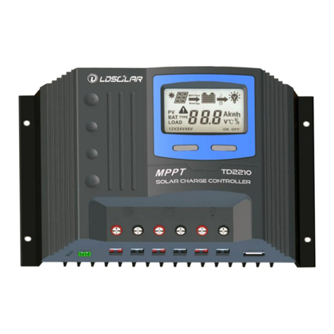
Ldsolar TRACER DREAM Series User manual

Tracer Dream series
User’s manual
of MPPT solar charge controller
MAX PV Input voltage 150V
12V/24V/48V 50A 60A
Dear Users:
Thank you for selecting our product. Please read this manual carefully
before you use this product.

Safety Tips
The input voltage of this controller is high, non-standard operation will
cause great damage to user. Please read this manual carefully and finish
the safety operation regulation before using this controller.
Please read all product safety caution and operation instruction carefully in this manual.
There are no components inside the controller that require maintenance or repair, users
are not allowed to disassemble and repair the controller by themselves.
It is better to install controller in the room, if install the controller outside, please keep
the environment dry, avoid direct sunlight and waterproof well.
Please install the controller in a well ventilated place, the heat sink temperature is very
high in process of working.
It is recommended to install suitable fuse or circuit breaker in front of controller.
Before installing and adjusting the wiring of the controller, be sure to disconnect the
wiring of the photovoltaic array and the fuse or circuit breaker near the battery terminal.
After installation, please check that all wiring connection are tight to avoid heat
accumulation due to loose connection.
Features:
This series of product adopt synchronous rectification technology and common negative design, and
equipped with LCD. The advanced MPPT control algorithm can quickly and accurately track the maximum
power point of photovoltaic array in any environment, obtain the maximum energy of solar panel in real time,
and improve the energy utilization of solar energy system. It can be used in communication base station,
household system, street light system and monitoring system and so on. Perfect electronic protection function
and patent terminal structure can avoid the damage of components and due to system fault and installation
error.
Advanced MPPT technology, fast and stable track the Maximum Power Point, tracking accuracy 99.5%.
Adopt Synchronous Rectification Technology, significantly improve the transfer efficiency of circuit,
maximum 98%.
With double peak or multi peak power tracking technology, when the solar panels is shaded or part of
solar panels is damaged, multiple peaks will appear in the I-V curve, and the controller can still accurately
track to the maximum power point.
PV array limited input power function, to ensure that the controller dose not overload operation under
any condition. When the power of solar panels is too high and the charging current is more than rated
current, the controller automatically reduces the charging power to make it work under the rated power.
Wide range of Maximum Power Point of PV array, Max PV input voltage 150V
12/24V/48VDC System voltage automatic recognition.
Humanized LCD displaying, multi button combination operation, dynamic display operation data and
working state
Built-in operation log, account system working state
Multi load control mode: Normal Mode, Sensor Mode, Timer and Sensor Mode
3 stages charging mode, Sealed, Gel, Flooded, Lithium several types battery charging procedure selection
(After the lithium battery is selected, the system voltage will not be recognized automatically)

Temperature Compensation Function(After the lithium battery is selected, there is no temperature
compensation function).
Accumulation function of charging and discharging, actual time display power generation function.
Fullest digital protection functions: Reverse connection, Overcharging, Over-discharging, Over voltage,
Overload, Short circuit, Overtemperature.
25mm2connectors, red and black connector distinguish plus and minus.
Using standard Modbus communication protocol based on RS-485 communication bus, maximize
satisfaction different occasions communication need.
Optional Blue-tooth or WiFi communication module, through the mobile phone APP can view and set the
parameters of the controller in real time.
Product Feature

No.
Name
No.
Name
1
Charging Status Indicator
7
Battery negative
2
with backlight LCD
8
Battery positive
3
Button Operation area
9
RS485 interface①
4
Mounting hole
10
External temperature interface②
5
PV positive
11
Dry contact③
6
PV negative
12
radiator
1Connect PC or expand Bluetooth WIFI module
2Connect external temperature sensor to sample battery temperature data.
3Switch for controlling battery electrical equipment according to the voltage value of battery. (Main for Inverter, Later, it
may be changed to normally open or normally closed)
Description of accessories
1
External
Temperature
Sensor
(Standard
Configuration)
The battery temperature data is collected to accurately adjust the
charging and discharging parameters as temperature compensation. The
standard line length is 1.5 meters (it can also be customized according
to the user's needs), and it is connected through the interface 10. Note:
when the remote temperature sensor is not connected or the
temperature sensor is damaged, the controller will default to 25 ℃ to
charge or discharge the battery without temperature compensation.
2
USB to RS485
Communication
line(Optional)
Special cable for connecting controller communication interface (RJ45
interface) and USB interface of PC, the standard line length is 1.5 meters
(it can also be customized according to the user's needs). The controller
can be real-time monitored and parameters set by the special upper
computer software
3
Bluetooth
module
(Optional)
The controller and Bluetooth module are connected by standard
network cable (parallel line). The mobile app software can monitor and
set parameters of the controller in real time through Bluetooth signal.
4
WIFI module
(Optional)
The controller and WiFi module are connected by standard network
cable (parallel line). The mobile app software can monitor and set
parameters of the controller in real time through WiFi signal.
Installation of Instructions
1.
Safety Considerations
This controller is base on solar panel feature researching, if use other power supply instead of solar panel,
the controller may cause fault.
It is better to install controller in the room, if install the controller outside, please keep the environment dry,
avoid direct sunlight and waterproof well.
The controller will be hot in process of working, please keep the environment ventilation,
away from flammable.

Solar panels will produce high voltage when there is light. Do not touch or short circuit wires and
terminals. When operation is required, pay attention to dry hands, use insulating tools and stand on
dry ground.
Only lead acid or Lithium batteries that meet the control range of this controller can be charged. For special
batteries, please consult with technical personnel.
The battery contains acid electrolyte. Please wear goggles when installing. If you contact the electrolyte
carelessly, please wash it with clean water
The battery has huge power, forbid any conductor short circuit the positive and negative poles of battery.
Suggest to adding a fuse between battery and controller. (Slow motion type, the action current of the fuse
should be 1.5 times rated current of the controller)
Please install the controller in a place where children can not touch.
2.
Precautions for use
The controller could detect the temperature of environment to adjust the voltage of charging,
so that the controller should be closed to battery as near as possible.
Recommend system current density of cables less than 4A/mm2, Unreasonable cable selection will increase
the system consumption, even burning.
Try to use multi strand copper wire in order to connecting with the terminal firmly. Loose power connection
and/or corroded wires may result in resistive connections that melt wire insulation, burn surrounding
materials or even cause fire.
Please keep the battery full charged (one time each month at least), or the battery will be destroyed.
This product have limited solar panel input power function, in theory, no matter how much power of solar
panel input, the controller will limited the input power under rated power, but must pay attention to the
following two points:
1) The short circuit of solar panel less than rated current of controller.
2) The Open Circuit Voltage of solar panel increased with decreasing temperature, please ensure in any
case, the Open Circuit Voltage of solar panel array will not exceed 150V, otherwise it will trigger
protection or damage to the controller.
3.
PV module connection requirements
1) Number of PV module in series
Due to the different types of photovoltaic modules in the market, the controller, as the core component of
the photovoltaic system, can adapt to various types of photovoltaic modules and can maximize the
conversion of solar energy into electric energy. According to the open circuit voltage (VOC) and maximum
power point voltage (vmpp) of MPPT controller, the series number of photovoltaic modules suitable for
different types can be calculated. The following table is the number table of photovoltaic modules in series,
for reference only:
System
Voltage
36cell
Voc<23V
48cell
Voc<31V
54cell
Voc<34V
60cell
Voc<38V
72cell
Voc<46V
96cell
Voc<62V
Thin film
moduleV
oc>80V
Max
Best
Max
Best
Max
Best
Max
Best
Max
Best
Max
Best
12V
4
2
2
1
2
1
2
1
2
1
1
1
1
24V
6
3
4
2
4
2
3
2
3
2
2
1
1
48V
6
5
4
3
4
3
3
3
3
2
2
2
1
2) Maximum power of PV array
The MPPT controller has the function of limiting the input power, that is, the controller can limit the power or
charging current within the rated range of the controller, and the maximum power of the controller can not be

greater than the rated charging power of the controller If the input power exceeds the rated charging power of the
controller, the controller will charge the battery according to the rated charging power of the controller. The actual
operation power of PV array meets the following conditions:
When the actual operating power of the PV array is less than the rated charging power of the controller,
the controller operates at the maximum power point of the PV array.
If the power of the PV array is greater than the rated charging power of the controller, the operation
time at full power of the controller will be extended, so more energy can be obtained to charge the
battery.
Attention:When the input wiring of PV array is correct and the actual power is more than 2
times of the rated power of the controller, the controller may be damaged. When the input
of PV array is reversed and the current actual power is more than 1.5 times of the rated
power of the controller, the controller will be damaged.
4.Fixation of controller
1)
The controller should be installed well-ventilated place, avoid direct sunlight, high temperature and do
not install in location where water can enter the controller. If it is to be sealed installation, please ensure
that the box can be reliably cooled.
2)
Please select correct screw to fix the controller on the wall or other platform. Screw M4 or M5, Screw cap
diameter less than 10mm.
3)
Please reserve enough space between the wall and controller, at least 150 mm up and down to allow for
cooling and cable connection.
4)
The mounting holes distance is 176mm*226mm,diameter of hole is 5mm.
5)
Aluminum fins for natural cooling, we strong suggest hanging installation, this is better for air flow
cooling effect.
5.Controller Connection
Before connecting, make sure that the system voltage matches with the selected products, and
whether the open circuit voltage and maximum power of the PV array are within the reasonable
range of the controller.
The following order of connection please do not free change,The controller has the function of
automatic identification of battery voltage. The battery should be connected first, otherwise it
may cause system voltage identification error.
All terminals are in tight status after factory, in order to well connected, please loose all terminals
at first.
If there is a short circuit at the terminal of the controller, it may cause fire or explosion! Please
operate with caution! It is strongly recommended to add air switches or fuses between the
battery and the controller and between the solar panel and the controller, and disconnect all air
switches or fuses before wiring (the air switch or fuse shall be selected according to 1.5 ~ 2
times of the rated current of the controller)
In order to avoid fault installation, please refer to below procedure
1)
As shown in the figure, connect the positive wire of the battery to battery positive terminal of the
controller(terminal 8), and the negative wire to battery negative terminal of the controller(terminal 7). The
connecting wire between the battery and the controller shall be as short as possible, and the recommended
distance is between 30cm and 100cm.
2)
As shown in the figure, connect the positive wire of photovoltaic array to PV positive of the
controller(terminal 5), and the negative wire to PV negative of the controller(terminal 6).
3)
Insert the standard external temperature sensor of the controller into terminal 10 of the controller. The
controller collects the temperature of the battery through the temperature sensor to compensate the

charging voltage. The temperature sensor should be close to the battery and away from other heat
sources, otherwise, the controller will have wrong action.
Note: the interface of temperature sensor and exposed copper part of wire shall not contact any
other live conductor, otherwise the controller will be damaged
4)
The interface of dry contact is on terminal 11 of controller. If you want to control other equipment,
switch of other equipment can be introduced to dry contact, and the maximum control current of dry
contact shall not be more than 2A.
Note: if the plug of dry contact is connected to the port of temperature sensor, the controller will be
damaged.
5)
If you want to connect the controller with a PC, you need a special RS485 communication
option. One end is RJ45 interface, which is connected to terminal 9 of the controller, and the
other end is USB interface, which is connected to the computer.
6)
If you want to connect the controller with the mobile phone app, you need a special WiFi or
Bluetooth communication option. One end is RJ45 interface, which is connected to terminal 9 of
the controller to communicate with the mobile phone through wireless signal.
For details of software use, please refer to the 《controller monitoring software operation manual》
6.Start Controller
Note: the controller supports starting the controller from the photovoltaic array end. When the
automatic battery identification function is selected, starting the photovoltaic array terminal first
may make the controller identify the system voltage error.
Before connecting the power supply, please confirm whether the wiring of battery terminal and
photovoltaic array terminal is correct.
After confirming that there is no error, first close the air switch or fuse at the battery end, so that the
controller can recognize the system voltage, and observe whether the LCD is on and whether the
interface is correct. If there is display or alarm status, please refer to 《Fault and Handling》 for
troubleshooting, and then carry out the following operation.
After the battery is connected normally, close the air switch or fuse at the photovoltaic array end. If the sunlight
is sufficient, the charging indicator light of the controller will flash, and the LCD interface will display the charging
state and photovoltaic array voltage, and start charging the battery. When disconnecting the system, please
disconnect the photovoltaic array first and then the battery.
7.
Grounding of solar system
Please bear in mind that this type of controller is a common negative design. Therefore, the
negative terminal of battery end and photovoltaic array end in the controller are connected

together. If the solar system needs to be grounded, you can choose any negative grounding!
8.
About LCD backlight
If no key is pressed, the LCD backlight will turn off automatically after 15s. When any key is
pressed, the LCD backlight will turn on again.
Battery Charging Process The controller has a three-stage charging mode, namely bulk charging, boost charging and float charging. Through these fast, efficient and safe battery charging methods, the service life of the battery can be
effectively extended.
Bulk Charging : Fast charging stage, the voltage of
battery is not reach to full charged set point. (Float
point or Boost point), the controller will be work at
MPPT mode. In process of Maximum Power of solar
panel charging.
Boost Charging : Each time the battery voltage less
than 12.6V, the controller will auto boost charging one
time. When the boost voltage reach to set point, the
controller will join into constant voltage charging
mode instead of MPPT mode, and gradually reduce the charging current, the boost charging continued
2H then go to float charging mode. (Due to the load capacity and generated changing, the controller
can't keep constant voltage charging, the constant voltage charging time will be accumulated,
accumulate 2hours cancel boost charging mode.
Float Charging :
After entering the floating charging mode, the controller will reduce the charging current
and charge weakly to maintain the battery at the floating charge voltage value. (if the voltage is not lower
than 12.6V, the boost charging mode will not be started, only floating charging will be carried out)
Main Interface
Name
Symbol
Indicate function
Solar Panel
Correct connect solar panel and in daytime
No connect solar panel or wrong connection
or at night
MPPT mode charging
Float charging mode
Boost charging mode
no charging
Data about charging
Battery capacity indicating
12V24V48V
Present System Voltage Show

Battery
Data about battery
Battery Type
Dry
Contact
Dry contact ON
Dry contact OFF
Dry contact Sensor and Timer mode output
Dry contact Sensor mode output
LOAD
Data about Dry contact
Dry contact working mode
Operation and Indication of controller
Main Interface
If no operation at main interface inner 10s, the main interface will cycle show battery voltage, PV array
voltage, charging current, battery type, temperature of environment, each parameter keep 3s.Long press “▲”
or “▼”button could speed loop display.
At the main interface short press “OK” button could on or off the Dry contact.
At the main interface long press “MENU” and “▲”5S could show work log, short press “▲”or“▼”
could see times of LVD, working days, times of over current protection, time of HVD. Press ”↺” could
return to main interface.
At main interface press “MENU” button could enter into menu interface. Press”↺” to exit from
any interface

At the menu interface press “▲”or“▼” could see the parameter, when reaching any parameter that can
be set, press “OK” button to enter the parameter setting state, press “▲” or“▼” could adjust the
value of the parameter. Long press “OK” button for 5s to save the setting data and exit the setting state
or press “↺” to exit without saving.
1)
PV power:This interface show the solar panels current output power.
2)
Accumulated Charging Power(AH): account current system generation ampere hour, long press “↺”button
could zero clearing.
3)
Float Voltage:
When the voltage of battery reach to this set point, the controller will start constant voltage charging
mode, limited the rising of battery voltage, decrease the charging current to keep the battery in full condition.
4)
Boost Voltage:When the battery voltage less than 12.6V, the HVD auto reach to 14.4V at the same time keep 2hours
then back to float voltage.
5)
Dry contact Low Voltage Reconnection(LVR) Voltage :
When the controller detected and closed the output of
load. If the controller is reconnect the output, the voltage of battery must be higher than LVR voltage or press “OK”
at main interface force to release.
6)
Dry contact Low Voltage Disconnection(LVD) Voltage :
When the voltage of battery is low, the load output
will be cut off. When the controller detected the battery voltage was less than LVD point, the cut off function will be
immediately working. At the same time, the status of controller is in lock. Users have to charge the battery, when the
battery voltage is higher than LVD voltage or press “ OK ” at main interface force to release, the dry contact will
resume power supply again.
7)
Dry contact Load mode:The control default load working 24hours. When the Load Working Time set to 24hours, the
load will keep working 24hours in no fault status. When the load working time set to ≤23H, it means the load start timer
or sensor function. If the battery capacity is enough, the load will be started at sunset. The load will work under timer
setting hours or stop working till sunrise.
8)
Temperature Detection inside controller : When the inside temperature of controller more than 75 ℃ , the
charging current will be down, exceed 85℃ closed charging.
9)
Battery Type Selection : Program Built-in 5 types battery data. Different battery will use different parameter.
(Default SEL battery parameter)
Note: for the control parameters related to the battery, we have fully considered the user's actual use.
If you want to modify, please refer to the battery supplier's suggestions, otherwise setting
unreasonable parameters will damage the battery. For lithium battery control parameters, please
adjust according to the battery supplier's recommendations.
Battery Type
SEL
GEL
FLD
Lithium iron phosphate battery
12V4 series LF4/24V8
seriesLF8/48V16 seriesLF16
Ternary lithium battery 12V3
seriesLI3/24V6
seriesLI6/48V12 seriesLI12
Over voltage protection
voltage
16.0V
16.0V
16.0V
16.0V
17.0V
Charging limit voltage
15.0V
15.0V
15.0V
14.8V
17.0V
Over voltage
reconnection voltage
15.0V
15.0V
15.0V
14.8V
17.0V
Boost voltage
14.4V
14.2V
14.6V
14.6V
12.6V
Float voltage
13.8V
13.8V
13.8V
14.2V
12.3V
Boost recovery voltage
12.6V
12.6V
12.6V
13.0V
11.5V
LVD recovery voltage
12.6V
12.6V
12.6V
12.6V
11.0V
LVD voltage
11.0V
11.0V
11.0V
10.5V
8.5V
Note: when the system is set to lithium battery type, the temperature compensation is zero and the
system will not be able to complete the automatic identification of battery voltage. After setting the type
of lithium battery, the system should be powered off completely and then powered on again to initialize the

system voltage.
Protection Function
Fault Symbol Indication
State
Symbol
Condition
LVD Protection
Battery empty and Warning Flash together
Battery Over Voltage Protection
Battery full and Warning Flash together
Controller Over Temperature
Protection
Temperature symbol and Warning Flash together
Solar Panel Over Voltage
Protection
Solar Panel symbol and Warning Flash together
The indicator lights flash
Normal charging
The indicator gradually on and off
PV voltage low can not start charging
The indicator off
Stop charging
Short Circuit and Reverse Connected Protection (Solar Panel)
When the solar panels have short circuit or reverse connection, the controller will be off the charging immediately, after
clearing of the short circuit, the charging will be automatically feedback.
Solar Panel Over Voltage Protection
When the input voltage from solar panel more than 150V, the controller will be off immediately, after input voltage
less than 145V the controller will be auto restart charging.
Reverse Connection of battery Protection
If the battery reverse connection, the controller will not destroy, corrected the connection the controller
will be normally working.
Note: since the controller can be started from the photovoltaic array end, the controller will be
damaged when the photovoltaic array is connected right and the battery end is reversed.
Battery Over Voltage Protection
When the battery voltage reaches the over-voltage cut-off point, the controller will automatically stop
charging and discharging the battery to prevent the battery and load from being damaged by the high
voltage of the battery.
Battery Low Voltage Protection (LVD)
When the voltage of battery was reach to LVD (Low Voltage Disconnection) point, the controller will be
auto closed the output in order to avoid over-discharge the battery.
Photovoltaic array over power protection
If the power of photovoltaic array exceeds the rated value of the controller, the controller can limit the
power or charging current to be within the rated range of the controller, so as to ensure that the controller
will not operate excessively.
Over Temperature Protection
When the internal temperature of the controller exceeds 75 ℃, the controller starts to alarm and reduce the charging
current. The temperature and warning flash. When the temperature exceeds 85 ℃, the charging is stopped. When the
temperature drops to 65 ℃, it will resume normal operation.
Lightning Protection
This product could only protect small lightning induction, we suggest users to use lightning rod at frequency area.

Fault and Handling
Fault Phenomenon
Possible reason
Solution
LCD no display after connected with
battery
Battery Low
Battery Reverse Connection
The connection cut off
Please confirm the voltage of battery reconnect
the controller with battery firmly and correctly.
Full of sunshine vertical on solar panel,
no solar symbol and no charging symbol
on LCD.
The solar panel connection open
circuit, short circuit, or reverse
connected
Please check the cable of solar panels if they are
correct connection and firmly.
The controller displaying LVD
The battery is over discharging
Please check the system design is reasonable or
not. Please full charge the battery
The controller displaying Over Voltage
Protection of battery
The voltage of battery is too high
Please first cut off the solar panel and see if the
voltage get down normal level. If the fault do
not finish, please cut off the battery with
controller and reconnect again
Technical Data
Mode
TD4515TU
TD4615TU
System Voltage
12V/24V/48V Auto
PV Max input voltage
At minimum ambient temperature 150V(+25℃ ambient temperature
138V)
PV Max input power
12V 660W;24V 1320W;48V 2640W
12V 800W;24V 1600W;48V 3200W
MPPT Voltage range
(VBAT+2V)---120V
MPPT tracking accuracy
≥99.5%
Controller conversion efficiency
Max 98%
MPPT limited Power Output
Yes
Self-consumption
≤2W
Max Charging current
50A
60A
LVD
11.0V ADJ 9V….12V;×2/24V;×4/48V
LVR
12.6V ADJ 11V….13.5V;×2/24V;×4/48V
Float voltage
13.8V ADJ 13V….15V;×2/24V;;×4/48V
Boost voltage
14.4V ; ×2/24;×4/48V Battery Voltage less than 12.6V Start Boost2hours(Li-battery no)
Battery Over Voltage Protection
16.5V ;×2/24V;×4/48V
Reverse Connection Protection
YES
Controller Over Temperature
Protection
Yes,75℃ Start decrease charging current,85℃stop charging,65℃return to work
Charging Type
MPPT (It can support solar panel end start-up system)
Charge Control mode
3 stage:Bulk(MPPT),Boost,Float
Optional battery types
Lead Acid, Flood, Gel, Lithium iron phosphate, Ternary lithium battery
Temperature Compensation
-24 mV /℃ for 12V ;×2/24V;×2/24V;×4/48V(Li-battery no compensation)
Cooling mode
Natural heat dissipation of radiator
Working Temperature
-20℃---+50℃
Terminals scale
25mm2
25mm2
Waterproof grade
IP32
Size
277mm×243.8 mm×110.9mm
277mm×243.8 mm×110.9mm
Net weight
4.2KG
4.5KG
*If the controller operates in high temperature environment, please reduce the rating
Version No.:V202001

Appendix一 Mechanical dimension drawing Uunit(mm)
This manual suits for next models
3
Table of contents
Other Ldsolar Controllers manuals
Popular Controllers manuals by other brands
SMC Networks
SMC Networks LC8-B*H*-M*-Q Series Installation and maintenance manual
Burda
Burda BHC4002-ER Installation & user manual
DMP Electronics
DMP Electronics 736V V-PLEX Module Advanced Settings Guide

SmartieParts
SmartieParts 9x installation instructions
Contro l4
Contro l4 C4-EA3-V2 installation guide
Regin
Regin RVAZ4-230 Instruction

