LEAB Clayton Power G3 Series User manual

LEAB Automotive GmbH
Thorshammer 6
DE-24866 Busdorf
User Manual
Version: 2.0
Issue date: 17.01.2019
G3 Sine Wave Inverters from
1012, 1024, 1312, 1512, 1524, 2012, 2324
Lightweight and compact sine wave inverter with switching power supply
technology
User Manual

User Manual About this Manual
Page 1 of 18
Table of Contents
1About this Manual ...............................................................................1
2General Safety......................................................................................2
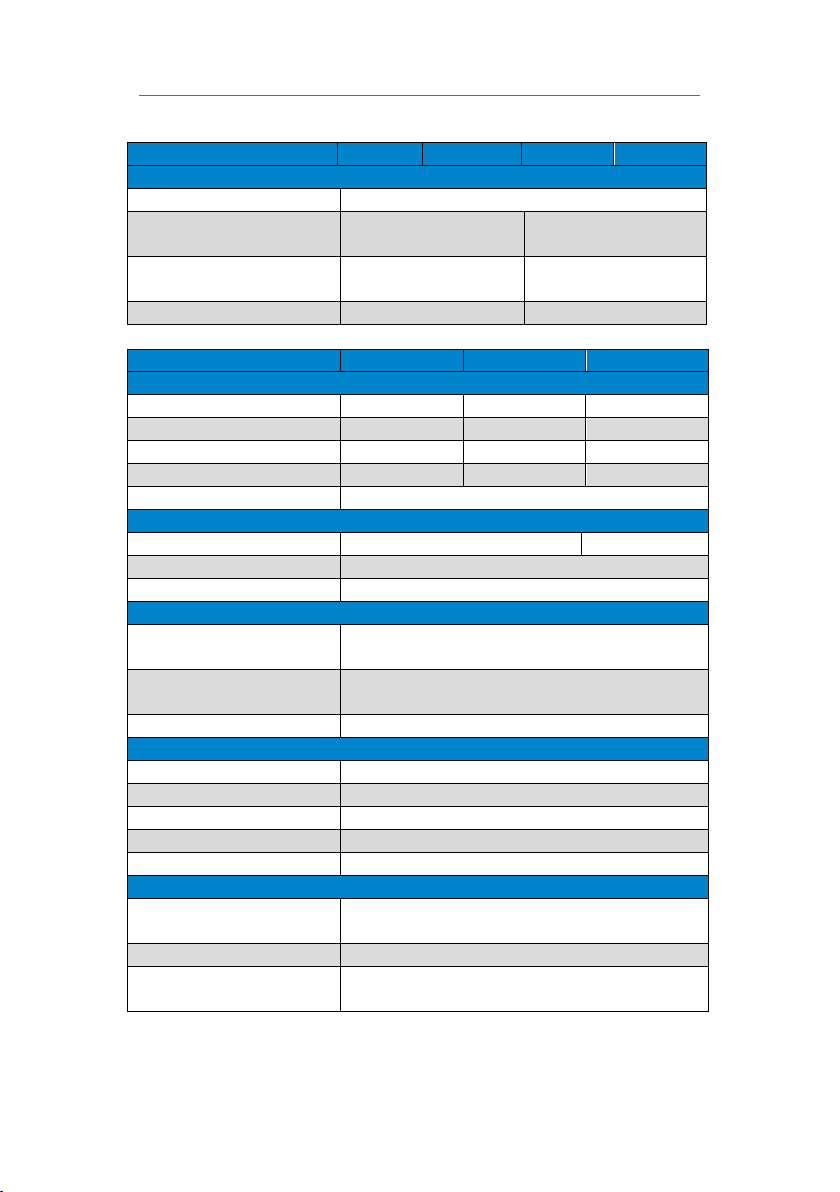
3Technical Specifications .......................................................................3
4Package Contents.................................................................................5
5About the Inverter ...............................................................................5
6Mounting .............................................................................................7
7Installation ...........................................................................................7
8Normal Operation ................................................................................9
9Connections .......................................................................................11
10 Control Displays and Error Descriptions ............................................12
11 Maintenance......................................................................................12
12 Mount Neutrik Plug............................................................................13
13 Disposal..............................................................................................14
14 EU Declaration of Conformity ............................................................14
1About this Manual
Read this manual carefully and keep it in a safe place. This manual is
intended for professionals in the automotive electrical field.
Throughout the manual, you will be alerted to warnings and safety notices
about potential hazards associated with handling the device. The colours
and signal words indicate the severity of the hazard:
Signal word
Meaning
DANGER
Warns of imminent danger resulting in death or
serious injury.
WARNING
Warns of a potentially dangerous situation that
can result in death or serious injury.
CAUTION
Warns of a potentially dangerous situation that
can result in moderate or minor injuries.
NOTICE
Warns of a potentially dangerous situation that
can result in material and environmental damage.

User Manual General Safety
Page 2 of 18
In this manual you will find the following symbols:
Shows you useful tips and information about the device.
Indicates a mandatory requirement for the following
instruction.
Shows the result of an instruction.
2General Safety
This manual supports the safe handling of the device. Use the device solely
in accordance with its intended use:
The G3 sine wave inverter with a lightweight and compact design has
switching power supply technology and is suitable for mobile and stationary
use. The G3 sine wave inverter converts DC voltage (12 V / 24 V) into
sinusoidal AC voltage, with which sensitive consumers are supplied.
Any modifications to the device or its components are prohibited and do
not conform to its intended use.
Observe the following safety instructions:
Device defect due to incorrect installation: Install the device in a dry
and cool location.
Danger from damaged, frozen or deformed batteries:
Before operation, make sure that the battery is undamaged and the
electrolyte is not frozen.
When handling open batteries, wear acid-proof clothing.

User Manual Technical Specifications
Page 3 of 18
3Technical Specifications
Model
1012
1312
1512
2012
Output power
Continuous power
1,000 W
1,300 W
1,500 W
2,000 W
Overload (1 s)
2,000 W
3,000 W
3,000 W
4,000 W
Overload (10 s)
1,500 W
1,800 W
2,000 W
2,800 W
Overload (15 min)
1,200 W
1,500 W
1,700 W
2,200 W
Degree of efficiency
90%
Internal consumption
Normal idling speed
10 W
15 W
Idling with search mode
< 2 W
Standby mode
< 5 mA
Operating temperature
Max. operating
temperature
+50°C
Min. operating
temperature
-20°C
Switch-off temperature
+80°C
Output voltage (AC)
Nominal voltage
230 V
Voltage tolerance
-10% ... +5%
Frequency
50 Hz
Frequency form
Sine
Max. distortion (THD)
3%
Input voltage (DC)
Nominal voltage of the
battery
12 V
Max. input voltage
15 V
Switch-off voltage
(Response time 3 s)
10.5 V
Switch-off voltage
(Response time < 10 s)
9 V
Switch-on voltage
(restart)
12.75 V

User Manual Technical Specifications
Page 4 of 18
Model
1012
1312
1512
2012
Output power
Protection class
IP21
Dimensions, housing
(LxWxH)
299 x 198.2 x 116 mm
376 x 198.2 x
116 mm
Dimension, housing with
connections (LxWxH)
334 x 198.2 x 116 mm
412 x 198.2 x
116 mm
Weight
6 kg
7.5 kg
Model
1024
1524
2324
Output power
Continuous power
1,000 W
1,500 W
2,300 W
Overload (1 s)
2,000 W
3,000 W
3,000 W
Overload (10 s)
1,500 W
1,800 W
3,000 W
Overload (15 min)
1,200 W
1,700 W
2,500 W
Degree of efficiency
90%
Internal consumption
Normal idling speed
10 W
15 W
Idling with search mode
< 2 W
Standby mode
< 5 mA
Operating temperature
Max. operating
temperature
+50°C
Min. operating
temperature
-20°C
Switch-off temperature
+80°C
Output voltage (AC)
Nominal voltage
230 V
Voltage tolerance
-10% ... +5%
Frequency
50 Hz
Frequency form
Sine
Max. distortion (THD)
3%
Input voltage (DC)
Nominal voltage of the
battery
24 V
Max. input voltage
30 V
Switch-off voltage
(Response time 3 s)
21 V

User Manual Package Contents
Page 5 of 18
Model
1024
1524
2324
Input voltage (DC)
Switch-off voltage
(Response time < 10 s)
18 V
Switch-on voltage
(restart)
25.5 V
Mechanical specification
Protection class
IP21
Dimensions, housing
(LxWxH)
299 x 198.2 x 116 mm
376 x 198.2 x
116 mm
Dimensions, housing
with connections
(LxWxH)
334 x 198.2 x 116 mm
412 x 198.2 x
116 mm
Weight
6 kg
7.5 kg
4Package Contents
Package contents
G3 sine wave inverter
x1
AC output plug, Neutrik NAC3FCB model –grey
x1
Phoenix plug, MSTB 2.5 / 3-ST-5.08 –green
x1
Manual
x1
5About the Inverter
Details
No.
Description
1
Inverter LED –blue
2
On/off button
3
Battery LED –red

User Manual About the Inverter
Page 6 of 18
Control displays
Pos.
Colour
Function
A
Green
Illuminates when
data connection
is “high”
B
Yellow
Illuminates when
data connection
is “low”
C
Orange
Illuminates when
remote switch is
“on”.
D
Not assigned
Details and connections
No.
Description
4
Connection, positive terminal of the battery
5
Connection, negative terminal of the battery
6
Data connection, model RJ12 (6P6C)
7
Data connection, model RJ12 (6P6C)
8
Data connection, Phoenix model
9
AC inverter output, Neutrik model
Control displays
between the data
slots

User Manual Mounting
Page 7 of 18
6Mounting
To mount the device, perform the following steps:
NOTICE
Choose a cool, dry and well-ventilated mounting site. The device
must be protected from dust and moisture.
Do not mount the device directly next to or above batteries.
Mount the device on a flat surface.
Optimum cooling is achieved with vertical mounting.
1. Fasten the device with screws to the 4 lateral holes (5 mm Ø).
The device is mounted.
7Installation
Determining the Cable Cross-section of the Input Lead (DC)
The following table shows the required cable cross-sections in relation to
the respective cable length. Select the cross-sections so that the voltage
drop to the inverter is no more than 250 mV.
To avoid voltage dips, select a higher cable cross-section for
consumers with high starting currents (e.g. motors,
compressors).
Cable Cross-
section
Device model
mm2
1012
1312
1512
2012
1024
1524
2324
15
-
-
-
-
1.5 m
-
-
25
1.5 m
-
-
-
2.5 m
1.5 m
-
35
2 m
1.5 m
1.5 m
-
3 m
2.5 m
1.5 m
50
3 m
2 m
2 m
1.5 m
-
3 m
2 m
70
-
3 m
2.5 m
2 m
-
-
3 m

User Manual Installation
Page 8 of 18
Connecting the Battery (DC Cable)
To connect the battery, perform the following steps:
1. Connect one wire of the DC cable to the negative terminal of the
inverter.
2. Connect one wire of the DC cable to the positive terminal of the
inverter.
3. Connect the negative terminal of the inverter to the negative terminal
of the battery.
4. Secure the positive cable as close as possible to the vehicle battery
with a suitable fuse.
Model
Fuse
1012
125 A, slow-blow
1024
80 A, slow-blow
1312
175 A, slow-blow
1512
175 A, slow-blow
1524
100 A, slow-blow
2012
250 A, slow-blow
2324
150 A, slow-blow
5. Connect the positive terminal of the inverter to the positive terminal
of the battery.
The battery is connected.
Connecting the Remote Switch
To connect an external remote switch, perform the following steps:
1. Connect an external on/off switch to the positive terminal of the
battery (DC voltage min. 10 V, max. 30 V).
Notice: Secure the on/off switch with at least 1 A.
2. Connect the on/off switch to the remote pin of the inverter.
The remote switch is connected.

User Manual Normal Operation
Page 9 of 18
Connecting Consumers
To connect consumers, perform the following steps:
1. Insert the plug of the consumer into the Neutrik input (grey) of the
device.
A Neutrik plug is included. You will find information on how to
install the plug on p. 13.
2. Ensure that the consumers are protected with an adequate protective
device.
The consumer is connected.
8Normal Operation
The inverter converts the DC voltage supplied by a connected battery into
sinusoidal AC voltage (230 V).
Switching on
The inverter is mounted and installed.
To switch on the device, perform the following steps:
1. Press the on/off button for 2 seconds.
Red and blue LEDs illuminate.
Red LED goes out.
Blue LED illuminates and indicates the start process.
Blue LED lights up continuously, AC voltage is activated.
The device is switched on.
Switching off
To switch off the device, perform the following steps:
1. Press the on/off button for 0.5 seconds.
Blue LED goes out.
Device switches off.
The device is switched off.

User Manual Normal Operation
Page 10 of 18
Standby Mode
If the AC voltage is not required continuously, a standby mode can be
activated. In standby mode, the internal consumption is less than 2 W. In
standby mode, the device generates a short pulse every 2 seconds.
If the actual consumption is more than 10 W, the device
switches on.
If the consumer is switched off, the device switches to
standby mode after 1 minute.
The standby mode cannot be activated or deactivated via an
external remote switch.
The standby mode is not suitable for lithium batteries.
Activating the Standby Mode
To activate the standby mode, perform the following steps:
The device is switched off.
1. Press the on/off button until the blue and red LEDs illuminate.
The standby mode remains active until it is deactivated.
The standby mode is activated.
Deactivating the Standby Mode
To deactivate the standby mode, perform the following steps:
The device is switched off.
1. Press the on/off button until the blue and red LEDs flash.
The standby mode is deactivated.

User Manual Connections
Page 11 of 18
9Connections
The pins for single wire communication are connected in parallel.
Plug, RJ12
Pin
Signal
Description
1
-Temp X1
Temperature sensor (-)
2
Ground
Ground, consumer (fused)
3
+Temp X1
Temperature sensor (+)
4
Sync_In/Out
Not assigned
5
Data
Single wire communication (Clayton)
6
Remote
Connection for connecting an
external on/off switch.
Plug, Phoenix Combicon
Pin
Signal
Description
1
Data
Single wire communication (Clayton)
2
Remote
Connection for connecting an
external on/off switch.
3
Not assigned

User Manual Control Displays and Error Descriptions
Page 12 of 18
10 Control Displays and Error Descriptions
Blue LED
Description
Steady light
Inverter in operation
…..…..…..…..…..
Start mode –Load adjustment
....….......................
Output overloaded
....……...........
Operating temperature too high
(automatic cooling and restart)
....……..
Short-circuit at the inverter output
....
Short-circuit in the power supply
....
Overload in the power supply during the
start process
Red LED
Description
Off
Battery voltage OK
Steady light
Low battery voltage (to prevent battery
draining, the device switches off after 1
minute)
..............
Battery voltage too high
Blue and red LED
Description
Flickering
Remote and mains switch on the device
switched on at the same time
....….......................
NTC error (internal temperature sensor)
....……...........
Overvoltage in the internal high-voltage
DC connection
....……..
Defect in half of the bridge circuit
....
Defect in the entire bridge circuit
11 Maintenance
Maintain the inverter at regular intervals.
Ensure that the wiring between the battery and the inverter is
secure.
To ensure the air supply, clean the ventilation grille of the
inverter.

User Manual Mount Neutrik Plug
Page 13 of 18
12 Mount Neutrik Plug
Use the following plug to connect the consumers:
AC output plug, type Neutrik NAC3FCB –grey
Connections Cable preparation
Sleeve Insert Clamp sleeve Screw connection
Coding, type B (grey)

User Manual Disposal
Page 14 of 18
13 Disposal
Dispose of the device in accordance with the Waste Electrical and
Electronic Equipment Regulations (WEEE).
The device must not be disposed of with household waste.
Take it to a recycling point or send it to your point of sale.
14 EU Declaration of Conformity
The G3 sine wave inverter
in models 1012, 1024, 1312,
1512, 1524, 2012, 2324
complies with the requirements of the following directives:
2014/30/EC: EMC
2014/35/EC: LVD
2011/65/EC: RoHS
The current and complete document is available on request from

User Manual Appendix
Page 15 of 18
Appendix: Use of Lead-acid Batteries
Selection of the Battery
Select a deep-cycle battery (e.g. lead-gel battery) as the power source for
the inverter. These batteries are designed for higher continuous loads and
cyclical discharges of up to 80% of their capacity without damaging the
battery.
Starter batteries are not suitable for operating an inverter.
Size of the Battery
When selecting the battery size, take the following into account: The
greater the battery capacity, the longer the inverter can be operated
without having to recharge the batteries.
Undersized batteries are often drained too deeply. This reduces their
efficiency and the service life of the batteries. The main causes of
premature ageing and defects are insufficient capacity, insufficient charging
and battery maintenance.
Wiring the Battery
Only connect batteries of the same type and size to each
other.
Never combine open and sealed batteries.
Clean the battery terminals with a brass wire brush.
Carefully fit the connecting terminals and tighten the clamping
screws.
Grease the battery connections.
Charge new batteries before use.

User Manual Appendix
Page 16 of 18
Connecting Batteries in Series
2 batteries connected in series
provide double the supply
voltage.
However, the total capacity does
not increase.
Example: 2 batteries 12 V / 100 Ah connected in series provide a supply
voltage of 24 V with 100 Ah.
Connecting Batteries in Parallel
2 batteries connected in parallel
provide double the battery
capacity.
However, the supply voltage does
not increase.
Example: 2 batteries 12 V / 100
Ah connected in parallel provide a
supply voltage of 12 V with 200
Ah.
Maintenance of the Battery
Lead-acid batteries must be maintained at regular intervals. The battery
must be maintained at least once a month in hot seasons and quarterly in
cold seasons. Older batteries should be checked every 14 days.
Maintenance of Open Batteries
With open batteries, check the condition of the liquid and measure the acid
density with an acid syphon.
To increase battery life, make sure the battery surface is clean and dry.
Carefully remove dirt and acid stains with hot water and a soda solution.
Remove the soda solution with fresh water and dry the battery. Ensure that
the venting flaps are clean and correctly fitted. Then check the installation
of the connecting terminals. Tighten the clamping screws if necessary.

User Manual Appendix
Page 17 of 18
Topping up Acid Level
Ensure that the cell grids are always covered with acid. Always use distilled
water to top up the battery, never normal drinking or sea water. Follow the
manufacturer's instructions when topping up the acid level.
Maintenance of Sealed Batteries
Sealed batteries require little maintenance. An inspection is limited to
measuring the battery voltage.
Storing the Battery
Store batteries in a cool, but frost-free and dry environment.
To prevent the battery from freezing, ensure continuous trickle
charging in cold conditions.
Never store batteries in a discharged state.
If stored for a long time, check the charge status regularly and
recharge if necessary.

User Manual Appendix
Page 18 of 18
Notes

LEAB Automotive GmbH
Thorshammer 6
DE-24866 Busdorf
Germany
Tel.: +49(0) 4621 9 78 60-0
Fax: +49(0) 4621 9 78 60-260
Web: www.leab.eu
This manual suits for next models
7
Table of contents