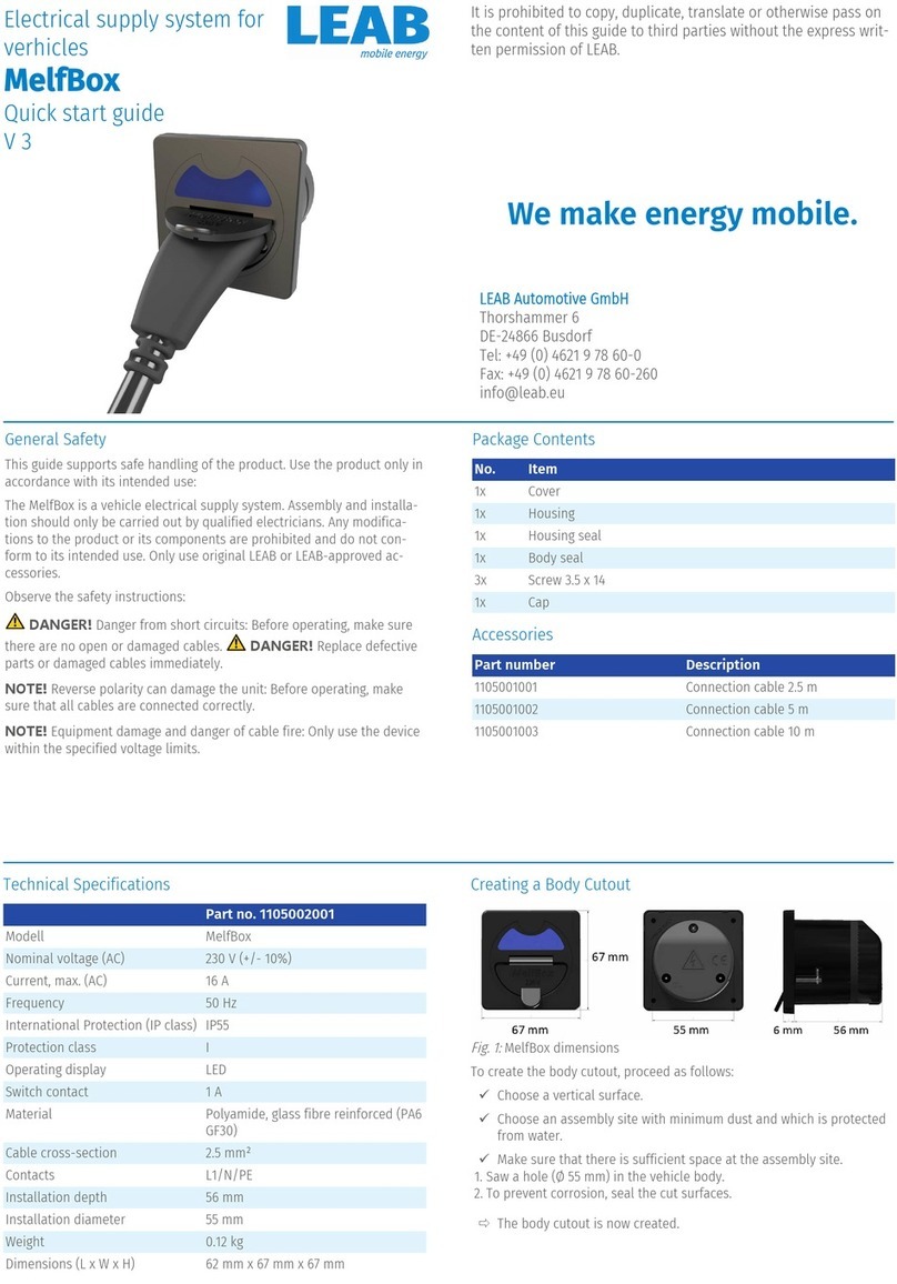
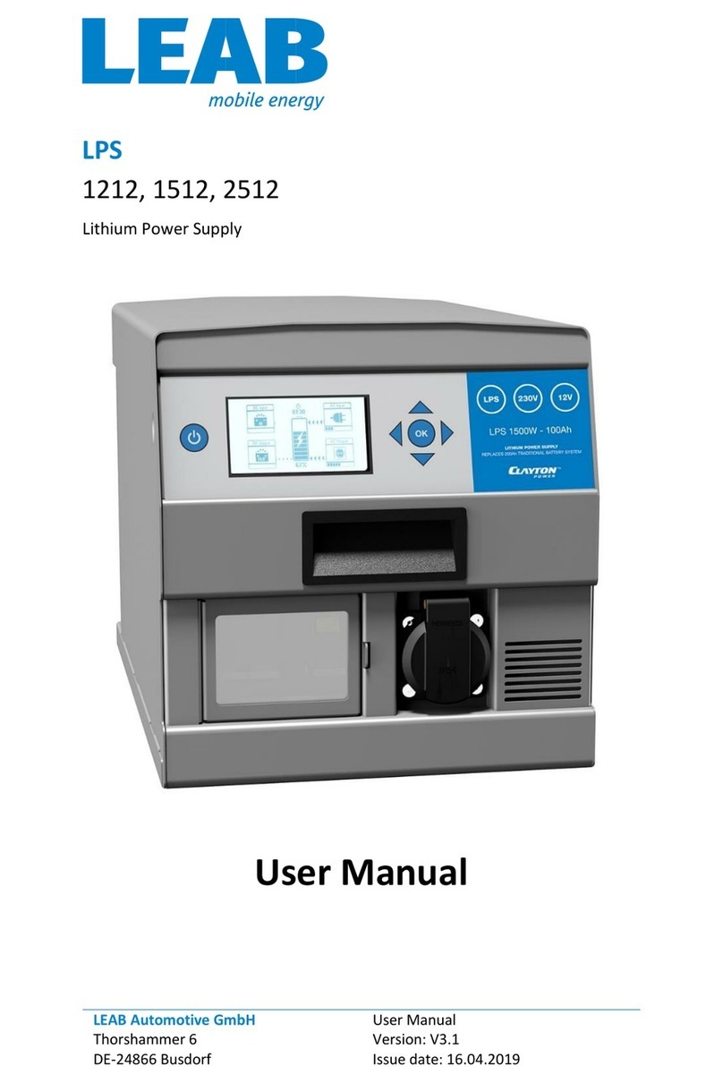
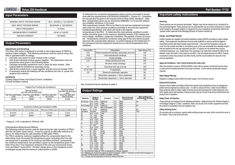
LEAB CDR 12/24 V User manual

Battery isolator
CDR 12/24 V
Quick start guide
V 1
General Safety
This manual will help you to handle the device safely. Use the device
solely in accordance with its intended use:
The CDR 12/24 V can be installed between the starter and auxiliary bat-
tery as an electronic charging current distributor. The charging current
can be distributed both bi-directionally and unidirectionally. The batter-
ies are charged almost loss-free and the plastic housing protects against
short circuits.
Thanks to a switch-off function, it can also be used as an automatic cut-
off relay to switch a consumer or an on-board supply system on or off.
The device is designed for an operating temperature of -40°C ... +60°C.
Observe the safety instructions.
WARNING!Risk of injury from damaged, frozen or deformed bat-
teries. Before using the battery, make sure that the battery is undamaged
and the electrolyte is not frozen.
WARNING!Risk of fire from overheated battery. Only charge bat-
teries in well-ventilated rooms and away from ignition sources.
WARNING!Danger of burns from escaping acid. Wear acid-proof
clothing when handling batteries.
WARNING!Danger from short circuits. Avoid contact of the screw
terminals with metallic and/or conductive vehicle parts.
Technical Specifications
Part no.: 1072001001
Modell CDR 12/24 V
Current limit 200 A I 100 A
Input voltage universal 12 V or 24 V
Typical switch-on voltage 13.5 V I 27.5 V
Typical switch-off voltage 12.8 V | 25.6 V
Quiescent current switched off < 1 mA
Quiescent current switched on < 25 mA
Operating temperature -40 °C ... +60 °C
International Protection (IP class) IP67
Dimensions (L x W x H) 134 mm x 95 mm x 31 mm (with
screw terminal height 58 mm)
Weight 700 g
About this Product
1 2 3 4 5
6
7
Fig.1:
CDR 12/24 V
1PIN 1 LED (connection for ex-
ternal LED) 2PIN 2 BI/UNI (connection for
changing the charging current
distribution)
3PIN 3 OFF (connection for ac-
tivating the switch-off func-
tion)
4PIN 4 ON (connection for the
bypass function)
5PIN 5 GND (connection for
GND) 6Screw terminal 2 (output)
7Screw terminal 1 (input)
Fig.2:
Dimensioned drawing CDR 12/24 V
LEAB Automotive GmbH
Thorshammer 6
DE-24866 Busdorf
Tel: +49 (0) 4621 9 78 60-0
Fax: +49 (0) 4621 9 78 60-260
It is prohibited to copy, duplicate, translate or otherwise pass on
the content of this guide to third parties without the express writ-
ten permission of LEAB.
We make energy mobile.

Package Contents
Item No. Item No.
CDR x 1 User manual x 1
Insulating caps x 2 Hex. nuts +washers,
M8 x 2
Assembly
NOTE!Maximum torque: 10 Nm
To assemble the device, perform the following steps:
1. Fasten the device to the 4 holes on the side (Ø 6 mm).
ðThe device is assembled.
Installation
NOTE!In vehicles with generator management, auxiliary batteries are
not sufficiently charged by conventional cut-off relays or current distrib-
utors. Recommendation: On-board charge booster BPC 12-12/40 (part
no.:1041003001).
NOTE!Maximum screw terminal torque: 20 Nm
To install the device, perform the following steps:
1. Connect the positive terminal of the starter battery to screw terminal 1
(input).
2. Connect the positive terminal of the auxiliary battery to screw terminal
2 (output).
3. Connect the plug contact PIN 5 (connection for GND) to a ground.
4. Connect the negative terminal of the starter battery and the negative
terminal of the auxiliary battery to a common ground.
ðThe device is installed.
NOTE!Various optional functions can be installed via the plug-in con-
tacts PIN 1-5 with 6.3 mm flat plugs.
Optional: Activate switch-off function
Prevents overcharging of fully
charged lithium-ion battery. Can
also be used as an automatic cut-
off relay
To activate the function, perform
the following step:
5. Switch the plug contact PIN 3 to
ground.
ðThe function is activated. The
device is switched off.
NOTE!The disconnection is independent of the direction of the char-
ging current selected.
Optional: Connect remote LED display
NOTE!External LED: Output 5 V,
max. 5 mA. Not included in the
scope of delivery.
To install the function, perform the
following step:
6. Connect the plug contact PIN1 to
the input of an external LED.
7. Connect the other terminal of
the external LED to ground.
ðThe function is installed.
Optional: Activate bypass function
Deactivates the voltage detection
through PIN 5 (GND) so that char-
ging current is distributed at any
voltage.
To use the function, carry out the
following step:
8. Switch the plug contact PIN 4 to
ground.
ðThe function is activated.
Optional: Change the charging current distribution (default:bid-
irectional)
To change the direction of the char-
ging current distribution to uni-
directional, carry out the following
step:
9. Switch the plug contact PIN 2 to
ground.
ðThe charging current distribu-
tion is unidirectional from
screw terminal 1 to screw ter-
minal 2.
To change the direction of the char-
ging current distribution to bidirec-
tional, carry out the following step:
10.Disconnect the connection cable
from plug contact PIN 2.
ðThe charging current distribu-
tion is bidirectional from screw
terminal1 to screw terminal2
or vice versa, depending on
where a higher voltage is
present.
Operating status (displayed via external LED)
External LED
status Function CDR
output Description/cause
Off Inactive Input voltage below the switch-on
voltage; PIN 3 connected to ground.
Steady light Active Input voltage within the switch-on
voltage; PIN 4 connected to ground.
Flashing, x 3 Inactive Input voltage out of voltage range
Flashing, 0.5 Hz Active/inactive
0.5 Hz Electrical voltage U>29.5 V
– Should the battery connected to the alternator or charger exceed a
voltage of 13.5 V or 27.5 V, the CDR will switch on the auxiliary battery
for charging.
– Should the voltage drop below 12.8 V or 25.6 V, the CDR will discon-
nect the batteries to prevent mutual discharge.
Disposal
Dispose of the device in accordance with the Waste Elec-
trical and Electronic Equipment Regulations (WEEE).
The system must not be disposed of with household
waste. Take it to a recycling point or return it to your point
of sale.
EU Declaration of Conformity
The CDR 12/24 V complies with the requirements of the fol-
lowing directives:
– 2014/30/EU: EMV
– 2011/65/EU: RoHS
LEAB Automotive GmbH // Thorshammer 6 // 24866 Busdorf
Other manuals for CDR 12/24 V
1
This manual suits for next models
1
Other LEAB Power Supply manuals
Popular Power Supply manuals by other brands
MERAWEX
MERAWEX ZDSO400-ER1 user manual
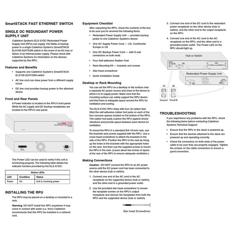
Cabletron Systems
Cabletron Systems SmartSTACK ELS100-S24TX2M Quick installation guide
ZyXEL Communications
ZyXEL Communications BPS-120 user guide

Cofem
Cofem ZAFIRPWS2 manual
Bluetti
Bluetti EB3A user manual
TDK-Lambda
TDK-Lambda IM-LZSA1000-2 Installation, operation and maintenance manual
