manuals.online logo
Brands
  1. Home
  2. •
  3. Brands
  4. •
  5. LEAB
  6. •
  7. Power Supply
  8. •
  9. LEAB MelfBox User manual

LEAB MelfBox User manual

Electrical supply system
for verhicles
MelfBox
Quick start guide
V 2
General Safety
This guide supports safe handling of the product. Use the product
only in accordance with its intended use:
The MelfBox is a vehicle electrical supply system. Assembly and in-
stallation should only be carried out by qualified electricians. Any
modifications to the product or its components are prohibited and
do not conform to its intended use. Only use original LEAB or
LEAB-approved accessories.
Observe the safety instructions:
DANGER!Danger from short circuits: Before operating, make
sure there are no open or damaged cables. DANGER!Replace
defective parts or damaged cables immediately.
NOTE!Reverse polarity can damage the unit: Before operating,
make sure that all cables are connected correctly.
NOTE!Equipment damage and danger of cable fire: Only use the
device within the specified voltage limits.
Package Contents
No. Item
1x Cover
1x Housing
1x Housing seal
1x Body seal
3x Screw 3.5x14
1x Cap
Accessories
Part number Description
1105001001 Connection cable 2.5 m
1105001002 Connection cable 5 m
1105001003 Connection cable 10 m
Technical Specifications
Part no. 1105002002
Modell MelfBox
Nominal voltage (AC) 230 V (+/-10%)
Current, max. (AC) 16 A
Frequency 50 Hz
International Protection
(IP class)
IP55
Protection class I
Operating display LED
Switch contact 1 A
Material Polyamide, glass fibre reinforced (PA6
GF30)
Cable cross-section 2.5 mm²
Contacts L1/N/PE
Installation depth 56 mm
Installation diameter 55 mm
Weight 0.12 kg
Dimensions (L x W x H) 62 mm x 67 mm x 67 mm
Creating a Body Cutout
Fig.1: MelfBox dimensions
To create the body cutout, proceed as follows:
üChoose a vertical surface.
üChoose an assembly site with minimum dust and which is pro-
tected from water.
üMake sure that there is sufficient space at the assembly site.
1. Saw a hole (Ø 55 mm) in the vehicle body.
2. To prevent corrosion, seal the cut surfaces.
ðThe body cutout is now created.
LEAB Automotive GmbH
Thorshammer 6
DE-24866 Busdorf
Tel: +49 (0) 4621 9 78 60-0
Fax: +49 (0) 4621 9 78 60-260
[email protected]
It is prohibited to copy, duplicate, translate or otherwise
pass on the content of this guide to third parties without the
express written permission of LEAB.
We make energy mobile.
Installation
To install the device, perform the following steps:
CAUTION!Install a suitable fuse in the vehicle (up to 16 A).
1. Route a connection cable (H07RN-F, 3 x 2.5) in the vehicle.
2. Attach the connection cable to the vehicle installation.
3. Pierce the housing seal at the intended location with a pointed
tool.
4. Feed the connection cable (H07RN-F, 3 x 2.5) through the hole.
5. Connect the wires of the connection cable to the corresponding
screw terminals.
ðThe device is installed.
Optional: Connect the immobiliser to the potential-free
switching contact (normally open contact)
To connect the immobiliser, proceed as follows:
CAUTION!Install a suitable fuse in the vehicle (up to 1 A).
1. Route a cable (H05RN-F, 2 x 0.5) for the immobiliser in the
vehicle and connect it to the specific vehicle installation (control
module or similar).
2. Insert the immobiliser cable (H05RN-F, 2 x 0.5) through the
second hole of the housing seal.
3. Insert the wires of the immobiliser cable into the push-in termin-
als (max. current: 1 A).
ðThe immobiliser is connected.
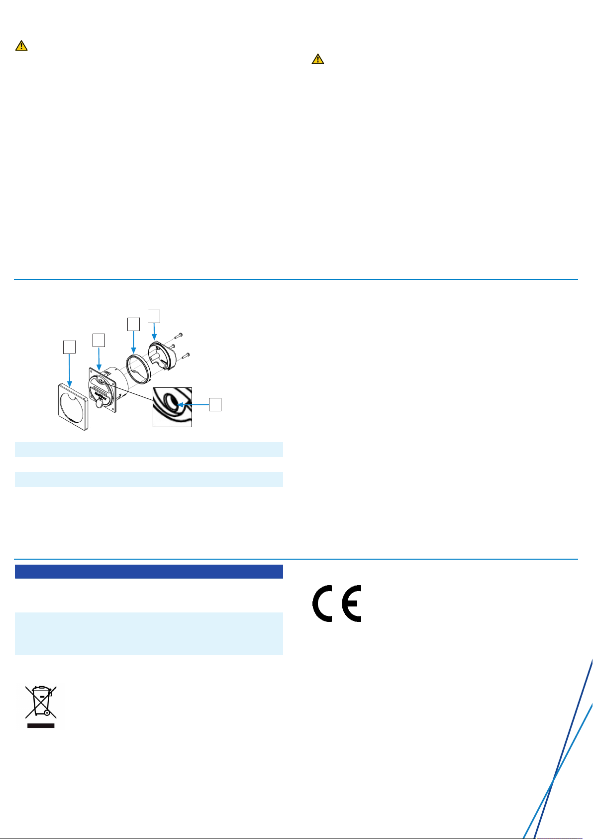
Assembly
1
2
3
4
5
1Cover 2Housing with body seal
3Housing seal 4Cap
5Retaining screw
To install the device, proceed as follows:
1. Place the housing seal in the cap.
2. Attach the cap to the supply unit with the 3 screws (3.5 x 14).
3. Check the tightness of the housing seal.
4. Push the supply unit into the body cutout.
5. Tighten the 3 screws on the front until the supply unit is firmly
seated in the body cutout (maximum torque:1Nm).
6. Attach the cover.
ðThe device is mounted and ready.
Operation
NOTE!An inactive immobiliser can cause equipment damage. The
immobiliser only works when the MelfBox is active (operating dis-
play lit up).
1. Plug the two-pin earthed plug of the connection cable into a 230-
V mains supply.
2. Open the flap of the supply unit.
3. Plug the coupling into the supply unit.
ðThe voltage input is provided at the load output of the supply
unit. Connected consumers are supplied. The operating display
shows the operating status of the MelfBox.
LED Operating status
Blue,
flashing
The MelfBox is active. A minimum of 50 W power is re-
moved from the supply unit (the greater the power, the
faster the flashing).
Yellow,
Steady
light
The MelfBox is active. No power is removed.
– Check the connection of the consumers.
– Check the fuse at the outlet of the MelfBox.
Disposal
Dispose of the device in accordance with the Waste
Electrical and Electronic Equipment Regulations
(WEEE).
The system must not be disposed of with household
waste. Take it to a recycling point or return it to your
point of sale.
EU Declaration of Conformity
The MelfBox complies with the requirements of the
following directives:
– 2014/30/EU: EMV
– 2011/65/EU: RoHS
LEAB Automotive GmbH // Thorshammer 6 // 24866 Busdorf

Other manuals for MelfBox

4

This manual suits for next models

3

Other LEAB Power Supply manuals

LEAB LPS Series User manual

LEAB

LEAB LPS Series User manual

LEAB CDR 12/24 V User manual

LEAB

LEAB CDR 12/24 V User manual

LEAB MelfBox User manual

LEAB

LEAB MelfBox User manual

Popular Power Supply manuals by other brands

BEL LEC120 Series Installation instruction

BEL

BEL LEC120 Series Installation instruction

Altronix SMPWP Series installation guide

Altronix

Altronix SMPWP Series installation guide

Norman BP320 Operation instructions

Norman

Norman BP320 Operation instructions

Mustek POWERMUST 636 Specifications

Mustek

Mustek POWERMUST 636 Specifications

Diamond Antenna GZV6000 instruction manual

Diamond Antenna

Diamond Antenna GZV6000 instruction manual

Siemens 4AV2302-2EB00-0A operating instructions

Siemens

Siemens 4AV2302-2EB00-0A operating instructions

VOSS.farming Sunny 200 instruction manual

VOSS.farming

VOSS.farming Sunny 200 instruction manual

SFC Energy EFOY Pro Series quick start guide

SFC Energy

SFC Energy EFOY Pro Series quick start guide

Argantix KDC 30-167 user manual

Argantix

Argantix KDC 30-167 user manual

Horizont trapper N45 instruction manual

Horizont

Horizont trapper N45 instruction manual

Matsusada R4K-36 Series Basic instruction manual

Matsusada

Matsusada R4K-36 Series Basic instruction manual

Scientific SME1300X Series user manual

Scientific

Scientific SME1300X Series user manual

AKG B 29 L Specifications

AKG

AKG B 29 L Specifications

Manson Engineering Industrial HCS Series user manual

Manson Engineering Industrial

Manson Engineering Industrial HCS Series user manual

Delta Elektronika SM 30-200 manual

Delta Elektronika

Delta Elektronika SM 30-200 manual

R&S NGL200 series Instrument Security Procedures

R&S

R&S NGL200 series Instrument Security Procedures

INIM Electronics IPS24060G Installation and Maintenance

INIM Electronics

INIM Electronics IPS24060G Installation and Maintenance

Elmdene LPS-ENC-T Installation & user manual

Elmdene

Elmdene LPS-ENC-T Installation & user manual

manuals.online logo
manuals.online logoBrands
  • About & Mission
  • Contact us
  • Privacy Policy
  • Terms and Conditions

Copyright 2025 Manuals.Online. All Rights Reserved.