MERAWEX ZDSO400-ER1 User manual

ZDSO400-ER1 User Manual Document No. 0717.00.95-02.0 Page:1/14
MERAWEX
MERAWEX
MERAWEX Sp. z o.o.
44-122 Gliwice
ul. Toruńska 8
POLAND
Phone: +48 32 23 99 400
Fax +48 32 23 99 409
e-mail: merawex@merawex.com.pl
http://www.merawex.com.pl
USER MANUAL
Emergency power supply units for Voice Alarm Systems
type
ZDSO400-ER1
compliant with standards:
EN-54-4:1997+A1:2002+A2:2:2006, EN-121001-10:2005, ISO 7240-4:2003
16.02.2017
1. TECHNICAL DESCRIPTION............................................................................... 2
2 PRINCIPLE OF OPERATION ............................................................................. 5
3. INSTALLATION AND CONNECTION ................................................................. 7
4. FIRST START ................................................................................................... 10
5. OPERATION ..................................................................................................... 12
6. SERVICING ....................................................................................................... 14
7. ADDITIONAL INFORMATION .......................................................................... 14
Document No. 0717.00.95-02.0

ZDSO400-ER1 User Manual Document No. 0717.00.95-02.0 Page:2/14
Warnings
Read this User Manual thoroughly before using the device.
Please don’t disassemble device which is energized. Touching the internal components
results in high risk of electric shock or skin burning.
During repair or exchange of the device please obey basic rules of handling electrical
equipment:
1. disconnect mains power and make sure that it couldn’t be accidentally switched on;
2. disconnect the batteries and make sure that its terminals couldn’t be accidentally
short-circuited (such event results in risk of fire or explosion)
3. make sure that the devices nearby are not powered and accidental touching them
does not create risk of electric shock.
Protect the device from the possibility of any items or fluids entering in – they can cause a
risk of electric shock and device damage.
Do not cover ventilation openings – doing so may result in device damage.
Provide a free space of at least 8 cm at the sides of the device, enabling its proper
ventilation.
The device must be supplied from the mains with a protective earthing terminal.
The device may interfere with operation of sensible radio and television equipment located
nearby.
1. Technical description
1.1 Designation
The emergency power supply ZDSO400-ER1 is intended to power voice alarm systems (VAS),
providing them power from main and backup power source, namely batteries, for needs of acoustic
amplifiers and separately for controllers and other VAS modules.
Emergency power supply allows to connect maximum 6 amplifiers, controller and 5 routers,
operating with one battery bank.
1.2 Design
Metallic cassette of ZDSO400-ER1 with height 1U, designed to mount in typical rack 19”.
Weight of power supply is 4,9kg.
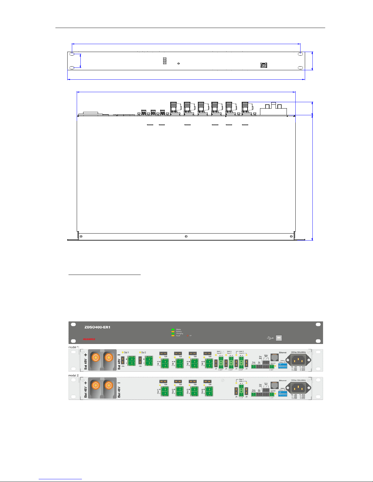
ZDSO400-ER1 User Manual Document No. 0717.00.95-02.0 Page:3/14
483
445
43290 31
465
31.8
Fig. 1. View and dimensions of ZDSO400-ER1 power supply – model 1
SUPPLIED ACCESSORIES:
1. Temperature sensor, length 1.5m with own plug,
2. Set of 6 plugs for connecting VAS amplifiers by outputs Out,
3. Set of 6 plugs for connecting continuous operation devices by output Aux,
4. Set of 3 plugs for connecting relay signalling outputs,
5. Plug for connecting external fault input signal, with preassembled jumper.
Fig. 2. View of ZDSO400-ER1 front panel and back panels
On a front panel we see:
set of 4 indication LEDs,
push-button ST used to:
a) start from battery (cold start – see par. 4.3)
b) manual start of battery circuit resistance test (see par. 4.3)

ZDSO400-ER1 User Manual Document No. 0717.00.95-02.0 Page:4/14
c) erasing errors (see par. 5.5)
USB socket for communication connection (type B).
Marking and meaning of indication LEDs is as follows:
Mains (Green) Charging (Green)
Battery (Yellow) Fault (Yellow)
On the back panel there are following components:
1. Mains socket IEC type C13 (male) to connect mains cable (230Vac, 50/60Hz)
2. Two M8 bolt terminals to connect battery 48V (BAT)
3. Socket for connecting temperature probe (Temp sensor)
4. Input of external fault signal (Ext fault)
5. Three outputs of relay signalling (Mains fault, Bat fault and Gen fault).
6. Six sockets (15A) to connect VAS amplifiers 48V (Out 1 ÷ Out 6) – in model 1
7. Four sockets (15A) to connect VAS amplifiers 48V (Out 3 to Out 6) in model 2
8. Two double and two single sockets to connect network controller and other VAS modules (Aux 1 to
Aux 6) – in model 1; two single sockets to connect network controller and other VAS modules
(Aux 5 and Aux 6) – in model 2
9. Ethernet communication socket (optional).
10. Tool (DIP switch) to set up battery capacity (charging current limit is calculated from battery
capacity) and maximum battery circuit resistance.
11. Fuses of outputs Out and Aux.
12. LED indicators of blown out fuses.
13. LED indicator of external fault state Ext fault.
1.3 Basic electric parameters
Table 1
Mains power voltage 230V +10% -15% 50/60Hz
Power factor 0.94
Efficiency (during battery charging) 84%
Leakage current in guard wire ≤1.5mA
Max. current consumption from mains 2.7A
Battery nominal voltage 48V
Floating voltage @25C 54.2V
Bulk charging voltage @25C 55.7V
Temperature compensation index for floating and bulk charging
modes - 80mV/ºC
Maximum capacity of connected battery 200Ah
Number of battery banks 1
Max. charging current 2…8A
*1)
Max. resistance of battery circuit 30…100mΩ
*2)
Current consumption from battery for own needs < 55 mA
Current consumption from battery after disconnecting by LVDD
(Low Voltage Disconnecting Device) < 1mA
LVDD battery disconnection threshold 40.8V
Range of output voltage changes 40.0…57.6V
*3)
Current capacity of main outputs foreseen for VAS amplifiers (Out)
- model 1
- model 2
6 x 15A
4 x 15A
Current capacity of auxiliary outputs foreseen for VAS components
operating continuously (Aux)
- model 1 (Aux 1/2, Aux 3/4, Aux 5, Aux 6)
- model 2 (Aux 1 and Aux 2)
4 x 2A
2 x 2A
Maximum continuous output current on 48V Aux outputs Imax. a 0…7A
*4)
Max. allowed total current sourced from battery, when main power
source is off 100A *5)
*1) Value of maximum charging current depends on battery capacity (see par. 1.4).

ZDSO400-ER1 User Manual Document No. 0717.00.95-02.0 Page:5/14
*2) Required value within given range may be set up with 10mΩ accuracy by DIP switch for selection of battery circuit
maximum resistance.
*3) Given range includes voltages between voltage on discharged battery (at the end of battery operation mode) and
bulk charging voltage, taking into account temperature compensation.
*4) Depending on capacity of connected battery. (see par. 1.4).
*5) At current 100A voltage drop inside power supply between battery connectors and amplifier output connectors
amounts 0.4V.
1.4 Dependence of maximum battery capacity on the current of Aux outputs
Current 16A, available from internal power supply, is used for both – for outputs loaded continuously
by VAS components (all outputs Aux) and for charging the batteries. As current of output Aux is limiting
the battery charging current, so maximum capacity of used battery is limited by this current of outputs Aux
in the way shown in below table.
Table 2
Max. current sourced continuously
from outputs Aux *) 0 1A 2A 3A 4A 5A 6A 7A
Max. capacity of batteries 200Ah 180Ah 160Ah 130Ah
100Ah
80Ah
50Ah 25Ah
*) This current is marked in the table of electric parameters as I max. a
1.5 Selection aspects of battery capacity
Determining the battery capacity must take into account cumulatively current consumptions during
battery operation in following order:
a. during watchdog for 6 or 24 hours
b. during transmission for 20 minutes voice messages with power lower by 10dB than nominal
power
c. during fire alarm for 10 minutes with power less by 3 dB than nominal power.
VAS components, mainly amplifiers, are working properly if supply voltage value is over given
threshold. Therefore battery circuit must fulfil requirements for voltage and resistance such, that during
fire alarm at maximum current wouldn’t happen amplifiers switch off.
VAS power system has following parameters when alarm is generated during battery operation:
- Maximum power of installed loudspeakers and current resulting from it during alarm (see par. 4.3)
- Resistance of current flow circuit between battery connectors and amplifier connectors (see par.
3.3.2)
From technical - and at the same point rational point of view - current flow could not cause on this
resistance voltage drop higher than 1.2V. This requires selection of battery in such way, that during
maximum alarm current flow, after 10 minutes, voltage on battery terminals will not drop below value
higher by 1.2V than amplifiers switching off voltage level, or LVDD battery disconnection threshold level.
1.6 Recommended operation conditions
Relative humidity max 80%
Direct sun exposure not permissible
Impacts during operation not permissible
Ambient temperature
limits of allowed storage temperature -40…+85C
operating temperature – class 3K5 by EN 60721-3-3 -5…+45C
2 Principle of operation
2.1 General
Power supply design is based on so called direct buffering operation. Mains power supply (which has
also role of a battery charger) is connected in parallel to outputs of ZDSO400-ER1 and external battery.
When mains power is present then it is delivering power to outputs and simultaneously charging the
battery. In this stage only sourcing current from outputs Aux to VAS controller or routers is allowed. After
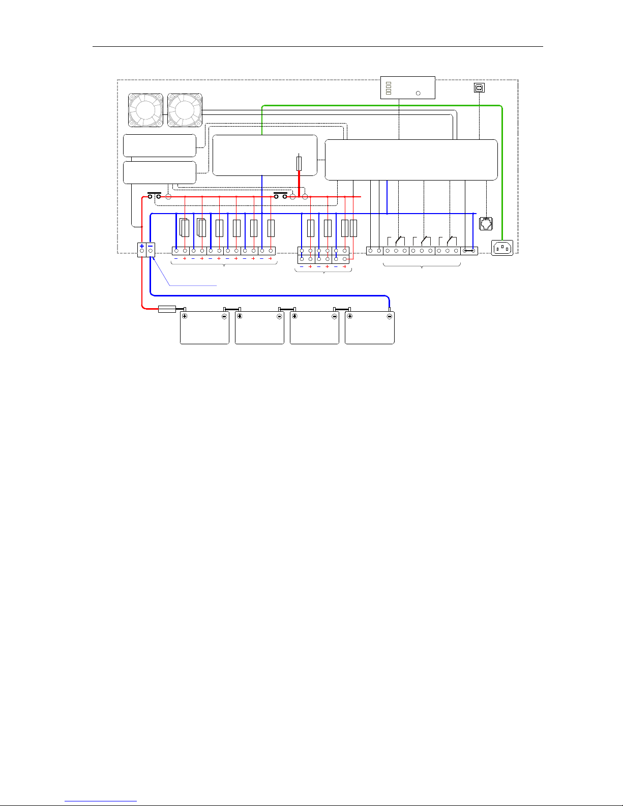
mains failure the load is transferred automatically to battery (battery operation mode). Block diagram of
power supply is shown on figure 3.
ZDSO400-ER1 User Manual Document No. 0717.00.95-02.0 Page:6/14
MICROPROCESSOR CONTROLLER
RECTIFIER 400W
LED SIGNALLING PANEL
1 2 3 4 5 6
POWER SUPPLY OUTPUTS FOR DSO MODULES
12V BATTERY 12V BATTERY
Ba
230V 50-60Hz
Mains
Battery
Charging
FAN
LVDD
Fault
BAT 48V
EX TERNAL
SIGNALLING INPUT
ETHERNET
DSO CONTROLLER/ROUTER
BA TTERY CONNEC TORS
USB SOCKET
CURRENT
MEASUREMENT SYSTEM
FAN
REMOTE SIGNALLING OUTPUTS
Mains faultBat fault Gen fault
Temp
sensor
POWER SUPPLY
RESISTANCE
MEASUREMENT SYSTEM
Out
Aux
1
2
3
4
5
6
BD
Ext
fault
ST
12V BATTERY 12V BATTERY
Fig. 3. Block diagram of ZDSO400-ER1 power supply
Power supply is designed to work with VAS systems, in which acoustic power amplifiers have own
mains power supply. It causes that there are two circuits with different character of current sourcing:
1. amplifiers of VAS, sourced from outputs Out:
a. when mains is present they are not sourcing current from ZDSO400-ER1;
b. after mains failure, when there’s no fire alarm, they source very low current from
power supply’s battery for their own needs;
c. if during mains failure fire alarm occurs, then they source from battery very large
current, defined by power necessary to transmit voice messages and alarm signals in
particular fire zones.
2. other components of VAS, operating continuously (controllers, routers, calling stations etc.);
because they have no own mains power supplies they need backup power source with
constant and relatively low power. Outputs Aux are doing this service.
ZDSO400-ER1 power supply provides following features besides already described main functions of
VAS power (outputs Out and Aux):
power from mains by own power supply 400W,
supervising an external battery, charging and monitoring it’s status,
testing the resistance of battery circuit (readings its value is possible by PC application via
USB),
protection of battery against deep discharge by LVDD,
monitoring of battery charging current, current on Aux outputs and occurrence of load on main
outputs Out when mains power is present (readings these values is possible by PC
application via USB),
disconnecting the outputs Aux by BD when battery terminals or outputs Out are shorted and
battery is not connected; it secures that voltage on outputs Aux is still present despite battery
failures previously described.
All functions of power supply are controlled by uP controller, receiving the signals from key points of
power supply, that inform about voltage, current, temperature, faulty states, etc. The controller is also
setting relays of external signalling, lighting LED indication and ensures communication with external
computer by USB link. If power supply is equipped with Ethernet module, there is possibility to control its
operation remotely.

ZDSO400-ER1 User Manual Document No. 0717.00.95-02.0 Page:7/14
2.2 Description of selected functions
2.2.1 “Cold start”
If mains power is missing, then there is possibility to start operation of power supply from battery by
using push-button ST on the front panel (so called cold start). Please hold the push-button button until
indication LEDs are lit, what takes ~5s. Battery voltage has to be over the minimum level ~44V.
NOTE: If power supply has been started from mains power and connected battery has voltage below
required level, then pressing push-button ST to connect battery will give no result.
2.2.2. Selection of battery operation mode
Power supply can operate with battery in two modes:
floating mode,
non-continuous battery charging.
Choosing one of these two modes can be done only by external computer by USB link.
Default factory setting is floating mode operation.
a. Floating operation mode
When the mains present, the charger of power supply maintains the external battery bank in its fully
charged state. Charger’s operation is controlled by the microprocessor controller of power supply, which
independently supervises the batteries, maintaining on them the floating mode voltage (depending on
ambient temperature, if the external temperature sensor has been connected). If the sensor is absent, the
controller maintains voltage corresponding to the ambient temperature of 25C.
b. Operation mode with non-continuous battery charging
If the mode with non-continuous battery charging has been selected, then it is activated with mains
supply presence, after charging battery fully, and after floating mode operation lasting for 48 hours (48h is
default factory setting, which could be changed by installing technician). After fulfilling above conditions
battery will be automatically disconnected from the charger, which will maintain the voltage on power
supply outputs at the level 0.2V higher than actual battery voltage. Such state lasts for 18 days (default
factory setting, which could be changed by installing technician) or to the moment of battery self-
discharging to the preset voltage level. In both cases the refillment charging will start. It means that
battery is reconnected to the charger and charged at increased voltage, in the same principle as bulk
charging. After recharging the battery and operating in floating mode for 48 hours battery will be again
disconnected from the charger for 18 days.
If the mains power fails or if during its presence high peak of current on outputs appears, then the
battery is reconnected immediately and momentary voltage drop seen on outputs doesn’t exceed 1.5V.
Operation with non-continuous battery charging increases lifecycle of batteries, by limiting time of
current flow through battery. It lowers positive electrodes corrosion of the cells and loss of water
contained in electrolyte.
3. Installation and connection
3.1. Installation, setting the switches, connecting
The power supply has a form of a cassette offering the IP20 ingress protection, designed for
installation in a typical 19” rack cabinet, using the four mounting holes located in the front panel (Fig. 1).
The rack dedicated to the Voice Alarm Systems must have IP30 ingress protection.
To install the power supplies in the rack you need to use guide rails. Guide rails supporting the power
supply cassette should be installed in such a way as not to cover the ventilation holes located on the both
sides of the cassette. The 8 cm ventilation space is required on both sides of the case.
3.2. Setting the switches of battery capacity and battery circuit resistance
At the rear side of power supply, next to mains socket, there is DIP switch, allowing setting of:
battery capacity Cap, which will operate with ZDSO400-ER1.
Setting the slide of the switch should be done according to calculation of capacity by DSO system
calculator and taking into account the time of operation during watchdog and total power of all foreseen
loudspeakers to be installed. Then for the calculated capacity right type of battery should be chosen, its

ZDSO400-ER1 User Manual Document No. 0717.00.95-02.0 Page:8/14
capacity (by rounding up the calculated value) and set the slide to capacity nearing or higher then chosen
for installation.
setting up maximum resistance of battery circuit Ri.
Setting the slide of the switch for maximum resistance of battery circuit on highest level depends on total
power of all foreseen loudspeaker to be installed. Value of the current during the fire alarm is closely
connected to this power, and it decides about the voltage drop in battery circuit. Right setting is shown in
Table 4 par. 4.3
The power supply controller adjusts operation parameters to the settings as they are made.
Power supply is designed to operate with batteries VRLA-AGM.
Near switch, under the mains socket, there is short description of particular position’s functions. Look
of the switch and settings description is shown on fig. 4.
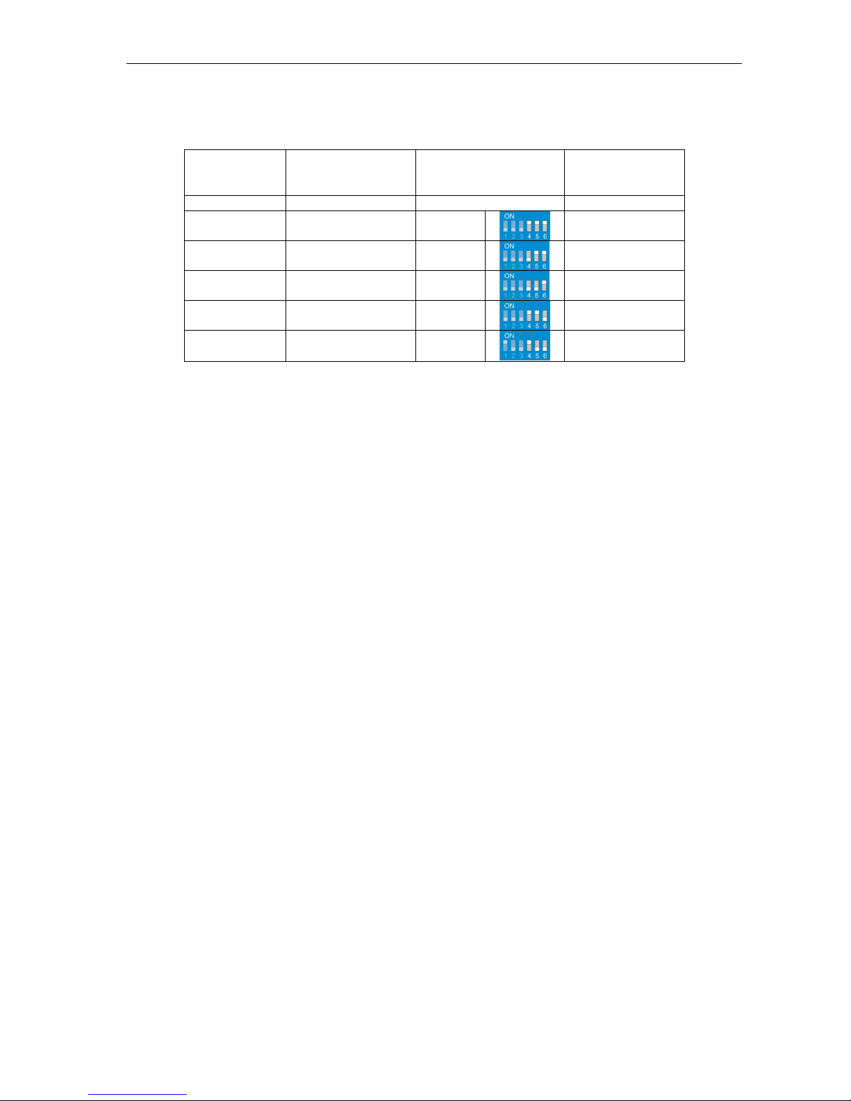
The minimal value of battery capacity Cap is 25Ah, which could be increased using 3 subsequent
slides of the switch 1, 2, and 3. Resulting capacity is a sum of 25Ah and values corresponding to every
slide, being in position ON (lifted up). Thus maximum possible capacity value is 200Ah.
The minimal value of resistance Ri is 30mΩ, which by 3 subsequent slides 4,5, and 6 could be
increased. Resulting resistance is a sum of 30mΩ and values corresponding to every slide, being in
position ON (lifted up). Thus maximum possible resistance value is 100mΩ.
Minimum
25 Ah
Maximum
200 Ah
Minimum
30 mΩ
Maximum
100 mΩ
Fig. 4 Look of the DIP switch for selection of capacity and battery circuit resistance with settings
description
3.3. Connection
Below table shows the types of connectors used in power supply with their maximum ratings and wire
diameters.
Table 3. List of ZDSO400-ER1 connectors
Output Type of plug used Model
1 2
Mains power
230Vac 50Hz/60Hz IEC C13 1 pc. 1 pc.
Outputs Out to supply the amplifiers PC 5/2-STLC-7.62
6mm2 41A with lock 6 pcs. 4 pcs.
Outputs Aux to supply auxiliary
modules
MC 1.5/2-ST-3.81
1.5mm2 8A 6 pcs. 2 pcs.
Temperature sensor input
Temp sensor
MC 1.5/2-ST-3.81
1.5mm2 8A 1 pcs. 1 pcs.
Outputs of relay signalling
Bat fault, Gen fault and Mains fault
FMC 1.5/3-ST-3.81
1.5mm2 3 pcs. 3 pcs.
Input of external fault signal
Ext fault
MC 1.5/2-ST-3.81
1.5mm2 1 pcs. 1 pcs.
Battery 48V Two-pole bolt terminal threaded M8
50mm2 100A 1 pcs. 1 pcs.

ZDSO400-ER1 User Manual Document No. 0717.00.95-02.0 Page:9/14
3.3.1 Connecting the power supply to the mains
Connecting the power supply to the mains should be implemented by using a 3-wire cable of the
1.5 mm2 cross-section, equipped with the IEC plug C13 type (to connect at ZDSO side).
NOTES:
1. The power supply is not equipped with its own mains switch, thus it is necessary to use
an external switch e.g. S301 C10A type, to connect it to the mains.
2. The required electric installation should be a permanent type and equipped with a surge
protection system.
3.3.2 Connecting the battery and protection of battery circuit
ATTENTION, safety concern:
1. Because power supply is not equipped with the fuse in the battery circuit, it is required
to install such fuse close to positive battery pole. It is allowed to put the fuse in a link
between two batteries.
2. Reversed connection of battery terminals versus markings on back panel terminals may
cause serious damages to both power supply and connected external devices
3. Batteries before installation should be pre-charged
Connection of a battery should be done by cables to terminals on a rear panel marked BAT 48V,
paying close attention to their polarity.
Connections should have minimum length. The leads connecting battery and power supply
should be close together (in parallel). To have the minimum resistance of the leads care should be
taken to tight the screws well.
Referring to par 1.5 one need to assume, that maximum drop on these connections should
not exceed 0.6V. Assuming this, one need to secure, that their total length does not exceed 2
metres, and cross section of cables should be chosen taking into account the power of
installed loudspeakers. Cross sections are shown in table 4 below.
Table 4
Power of loudspeakers [W] Suggested cross section of
cables
Total resistance of cables and
battery fuse [mΩ]
≤1500 10mm
2
[1.8mΩ/1m] ≤12 mΩ
1500 < P
L
≤ 3000 16mm2 [1.1mΩ/1m] ≤ 8 mΩ
3.3.3 Connecting the amplifiers of VAS system
The ZDSO400-ER1 power supply is equipped with 6 high power outputs Out to connect
amplifiers, with 2 models possible:
Model 1
It has 6 connectors, allowing connection of amplifiers with power 500W each.
Model 2
It has 4 connectors, allowing connection of amplifiers with power 500W each.
Connections of all amplifiers have to be done by cables with such cross section, that voltage drop
on them made by current flow during fire alarm will not exceed 0.2V.
Therefore connections of all amplifiers have to be done by cables with cross section 4mm2.
If main amplifier has in DSO system its backup amplifier, then is possible to connect both
amplifiers to the same output (if there is no free output left). This connection need to be done outside
the power supply.
3.3.4 Connecting the other components of VAS system
Components of VAS system, which need continuous power, have to be connected to output Aux.
They are organized in pairs, protected by common fuses (Aux 1 with Aux 2 and Aux 3 with Aux 4).
Two extra outputs Aux 5 and Aux 6 are equipped with own independent fuses. Most important
components of VAS system (e.g. controller) should be connected to these independent
outputs!

ZDSO400-ER1 User Manual Document No. 0717.00.95-02.0 Page:10/14
3.3.5 Connecting the external fault signal
Power supply has one input to connect signaling of external fault, which socket is located on a
rear panel. Fitting plug is supplied with accessories. It has factory installed jumper and serves to be
put in the input Ext fault, when it is not used, because the input is activated by open circuit between
its contacts.
3.2.6 Leading out the remote signalling
Outputs of remote relay signalling of ZDSO400-ER1 are 3-pin independent sockets. The power
supply unit is supplied with 3-pin plugs. By proper cabling connection the normally connected (NC) or
normally open (NO) contacts of the internal relays can be used.
3.3.7 Connecting the temperature sensor
External temperature probe, supplied with accessories, should be connected to right socket (Temp
sensor). The sensor should be placed between the walls of two adjacent batteries, in contact with
walls!
4. First Start
4.1. The initial information
The first start of the VAS system including the ZDSO400-ER1 and connected battery should be done
by qualified service personnel of the Manufacturer or the properly trained authorized personnel.
The tests during the first start of the system are necessary to ensure safe and reliable operation – both
from the mains and battery backup power.
At the first start, you should check the system completeness and all VAS modules for their compliance
with the electrical specifications of the object in which the system is to operate. The checking should also
include the correctness of connections as well as the connected battery and the signaling circuits.
ATTENTION:
If any of amplifiers, when equipment is already powered on and is connected to the battery, starts
sourcing current from output Out, as a result of internal fault or disconnection of its individual mains
power, then such state can lead to uncontrolled discharging of battery even though power supply is
operating properly.
4.2. Start-up sequence
Suggested sequence of switching on devices in the VAS system is like follows:
1. All devices should be switched off (all AMPs and ZDSO400-ER1)
2. Set up battery capacity on a rear panel according to paragraph. 3.2 and table 5 in par. 4.3.
3. Set up battery circuit resistance on a rear panel according to par. 3.2 and table 5 in par. 4.3.
4. Connect 24V battery to the unit, after checking if their polarity is right
5. Put in the fuse insert into a fuse holder
6. Switch on the mains power (230Vac) of all AMPs and ZDSO400-ER1 power supply
7. Test the battery circuit resistance according to par. 4.3
8. Check the operation and signaling with disconnected mains power in accordance with
par. 4.4
9. Check the operation and signaling with battery disconnected in accordance with par. 4.5.
4.3. Tests of battery circuit resistance during start up
Limitation of the maximum battery circuit resistance is caused by securing on the outputs of power
supply voltage value enough to proper operation of VAS system during fire alarm coming when in battery
operation mode.
Maximum possible value is 100mΩ, however for loudspeakers power higher than 500W [column 1] the
setting of the limit for battery circuit resistance should be lower (see Table 5.)
In practice battery circuit should have lower resistance than the set maximum value, and the margin to
the limit has to take into account increase of resistance due to battery aging.
In the Table 5 below [in column4] there are shown resistance values for battery circuits as function of
maximum total VAS system power, corresponding to total power of all loudspeaker foreseen for
installation [column 1].
ZDSO400-ER1 User Manual Document No. 0717.00.95-02.0 Page:11/14
For selection of the maximum resistance (its setting out) one need to use Table 5.
Table 5
Loudspeaker
power
[W]
Expected battery
circuit resistance
value *1) [mΩ]
Setting of maximum
battery circuit
resistance Ri [mΩ]
Resistance
margin *2)
[mΩ]
1 2 3 4
500 ≤ 40 80
40
1000 ≤ 36 70
34
1500 ≤ 28 60
32
2000 ≤ 22 50
28
2500 ≤ 18 40
22
3000 ≤ 18 40 22
Explanation for the Table 5
*1) Battery circuit resistance value, which was measured by ZDSO400-ER1 power supply. It periodically
takes this measurement. It exists possibility to initiate the battery circuit resistance test by pressing and
holding ST push-button on a front panel for about 10s. Carrying such test is possible only for pre-charged
batteries. Viewing the value of battery circuit resistance is possible by use PC application via USB
connector with a software application supplied by manufacturer.
*2) Resistance margin [5] is the difference between the setting of maximum resistance [4] (over this level
fault signal is generated) and expected battery circuit resistance value [3]. Resistance margin shown in
the table is equal approximately to nominal resistance of batteries with capacity sufficient for system with
power presented in column [1].
4.4. Checking the ability of maintaining output voltage after mains power
disconnection
Please, disconnect the mains power. The power supply should start operating in the battery mode,
supplying voltage to its all outputs for powering the VAS modules. Check the voltage presence and value
by a voltmeter.
In this state, the Mains LED on the front panel of the ZDSO400-ER1 should go dark and the Fault and
Battery LEDs should be lit.
The both relays of Mains fault and Gen fault should enter the idle mode (the position of contacts should
follow the picture near the connector). The state of the relays can be checked by an ohmmeter.
The connected VAS modules should function normally during the checking.
4.5. Checking the operation when battery is disconnected
When ZDSO400-ER1 is powered from the mains, please break the battery circuit. This event should
be detected during nearest test, what can take up to 100s.
Disconnected battery state should be noticed by ZDSO400-ER1 power supply controller, which has to
lit Fault visual indication and change the state of relays Bat fault and Gen fault to idle mode (the
contacts position following the picture close to the connector).
During the above test, the connected VAS modules should operate normally

ZDSO400-ER1 User Manual Document No. 0717.00.95-02.0 Page:12/14
5. Operation
5.1. The initial information
Output voltages and signalling thresholds are preset as factory default values. Power supply after
installing requires supervision by the service team as some emergency states may occur during the
operation of the device.
ATTENTION: In the system with battery backup power source, the power supply should subject periodic
checking and tests in line with directions written in instruction manual of this system.
5.2. Operational safety
The power supply unit is a Class I device according to the standard EN 60950-1:2006+A1:2009
(IEC950), designed for connecting to a permanent, one-phase installation using an earthing cable,
according to the standard HD 60364-4-41:2007: Low-voltage electrical installations - Part 4-41: Protection
for safety - Protection against electric shock
The metal case of the power supply unit is connected to a guard terminal (PE). The circuits used for
connecting the battery, remote signalling and power outputs are separated from the power supply circuits
and from the case.
The EMI filters used in the power supply are equipped with the Y2 class capacitors causing the
appearance of the leakage current in the guard wire of maximum 1.5 mA.
NOTES:
1. Relay contacts for remote signaling are fully separated (galvanically isolated) from all other circuits
(including the output circuits).
2. Input of external fault signal is referred to the potential of negative pole of the battery bank.
5.3. Digital communication
The front panel of the emergency power supply unit is equipped with a USB communication socket
used routinely for servicing. The PC software allows performing diagnostic works, making possible
checking numerous operation parameters of the power supply and modifying its default settings. This
output is galvanically insulated from all other circuits of the emergency power supply unit.
Optionally, the emergency power supply may be equipped with an Ethernet interface, enabling operation
within a TCP/IP network. Server with ModbusTCP protocol enables device control and supervision.
Detailed information can be obtained from the manufacturer.
5.4. Signalling of the operation state
The emergency power supply is equipped with LED indication and remote signalling. The LED
indication is used for bringing attention of the personnel to the operation state of the device and to inform
about the reason of a potential malfunction.
Fault indication is maintained as active until fault condition disappears (root cause of fault condition is
removed or disappears).
Visual fault indication consists of four LEDs placed on the front panel of power supply. Three of them
are indicating current operation mode (Mains – green, Battery – yellow, Charging – green) and fourth is
indicating fault (Fault – yellow).
The remote signalling includes three sockets marked Mains fault, Bat fault and Gen fault. Each of
the sockets has three pins, switchable by relays, electrically separated from all other circuits. During
normal operation of the emergency power supply unit, relays are in ON state. It means that indication of
Mains Fault (power failure), Battery Fault and General Fault are executed by switching off the
corresponding relay.
The contacts position in this state (so called zero-voltage state) is shown next to connector of Mains
fault relay.
List of states of the LED indication and remote signalling is presented in the tables below.
Note:
By a term “rectifier” is understood the power supply equipment with charger functionality

ZDSO400-ER1 User Manual Document No. 0717.00.95-02.0 Page:13/14
Table 6. LED indication on a front panel.
DESCRIPTION
COLOUR STATE EVENT DESCRIPTION
Mains green lit Normal operation state when the mains power present.
dark No mains power or rectifier fault.
Battery yellow lit Battery operation (no mains or rectifier fault).
dark Normal operation state when the mains present.
Charging green
blinking Bulk or refillment charging
lit Charging during floating mode
dark Charging is finished.
Fault yellow
lit Fault occurred within the power supply or external fault.
blinking External fault signal active at Ext fault input.
*)
.
dark Normal operation state at mains power present – no fault
signals
*) If together with the external fault signal active any internal fault occurs, the Fault LED will be lit continuously
Table 7. LED indication on the rear panel.
DESCRIPTION COLOUR STATE EVENT DESCRIPTION
From Out 1
to Out 6 yellow lit Particular output fuse blown out.
dark Output is powered.
From Aux 1
to Aux 6 yellow lit Auxiliary output fuse blown out.
dark Output is powered.
Ext fault yellow lit External fault signal terminals open (fault)
dark External fault signal terminals shorted (normal operation)
Table 8. Relay remote signalling
DESCRIPTION STATE EVENT DESCRIPTION
Mains fault on Normal operation state at the mains present.
off No mains power or rectifier fault.
Bat fault
on Correct battery condition.
off Battery disconnected, high resistance of battery circuit or battery
voltage below a preset level (battery discharged).
Gen fault on No fault.
off Fault inside the power supply or external fault
*)
*) there are also signalled: blown fuses status on Out and Aux outputs and external fault incoming on input Ext fault
5.5. Erasing alarms
In the ZDSO400-DR1 power supply push-button ST may be used (by short pressing) to erase two
possible internal errors.
failure of voltage regulation circuit in the charger,
checksum error in EPROM memory.
Other functions of ST push-button were described in par. 2.2.1 and 4.4
5.6. Maintenance
The device does not require any specific maintenance operations to be performed. Please take care
to maintain clean and tidy area around the emergency power supply during normal operation.

ZDSO400-ER1 User Manual Document No. 0717.00.95-02.0 Page:14/14
6. Servicing
6.1. Fuses
Fuses are accessible for the service team easily and their parameters are specified below in table 9.
Fuse holders are located on rear panel.
Table 9.
Protected circuit in the power supply Fuse type, value and description
Outputs for amplifiers 15A (flat, car style)
Auxiliary outputs 48V 2A (flat, car style)
The VAS system personnel can only exchange the fuses mentioned above. If other fuses used inside
the power supply are broken, a repair performed by qualified service personnel is required.
6.2. Diagnosing faults and troubleshooting
Most cases of malfunctions which can occur during device operation are indicated and handled by the
microprocessor installed in the device. The ZDSO400-ER1 is equipped with 12 fuses for model 1 and 10
fuses for model 2. They can be replaced by qualified service personnel. These are fuses of output circuits
– for powering the amplifiers, VAS controller / routers or the smoke and heat control system devices.
Damage of output fuses may happen due to short circuit on the output or significant overload. The fuses
of outputs mentioned in Table 8 are accessible on the rear panel of the power supply.
Warranty and after-warranty repairs should be performed by service of the manufacturer or by an
authorised service partner of the manufacturer.
6.3. List of of indicated errors
Table 10. Power supply faults indication by LED Fault on a front panel.
Description
No battery or connected battery voltage is too low.
Output voltage outside the limit set when mains power is present.
Output fuse faulty on
Out
or
Aux
outputs.
External fault (open circuit on the
Ext fault
input
)
–
LE
D blinking
Faulty rectifier or mains power failure
Missing or faulty temperature sensor
High battery resistance
7. Additional information
7.1. Remarks of the manufacturer
The manufacturer reserves the right to introduce design and technology changes to the product,
without diminishing its quality.
7.2. Handling the packaging materials and used products
Product packaging is made of non-hazardous materials (wood, paper, cardboard, plastics),
which can be recycled. Packages which are no longer needed should be passed on to a waste
collection station, after they had been sorted.
The used product is a non-hazardous waste which should not be disposed of in the
general waste bin, but it has to be transferred to the local waste collection/recycling station
accepting electric and electronic equipment.
Proper handling of used electric equipment contributes to avoiding harmful influences on
people and environment resulting from improper warehouse storage and processing of such
equipment.
Table of contents
Other MERAWEX Power Supply manuals

MERAWEX
MERAWEX ZDSO400-DR2 User manual

MERAWEX
MERAWEX ZUP-230V User manual

MERAWEX
MERAWEX ZSP135-DR-2A-1 User manual

MERAWEX
MERAWEX ZSP100 Series User manual

MERAWEX
MERAWEX ZSP135-DR-2A-1 User manual

MERAWEX
MERAWEX ZMS-1A-12V10A User manual

MERAWEX
MERAWEX ZUP-230V-BM-400S User manual

MERAWEX
MERAWEX ZSPM-75-05 User manual
Popular Power Supply manuals by other brands

TDK-Lambda
TDK-Lambda CUS800M instruction manual

Broadata Communications
Broadata Communications Link Bridge LBC-24PI user manual

VOLTCRAFT
VOLTCRAFT FPPS 9-7.2W operating instructions

Musical Fidelity
Musical Fidelity TRIPLE-X170 Instructions for use

Altronix
Altronix AL400UL3 installation guide

VIGO System
VIGO System MPPS-01 user guide


