LEAB LPS Series User manual

LEAB Automotive GmbH
Thorshammer 6
DE-24866 Busdorf
User Manual
Version: V3.1
Issue date: 16.04.2019
LPS
1212, 1512, 2512
Lithium Power Supply
User Manual

Installation instructions About this Manual
Page 1 of 25
Table of Contents
1About this Manual .................................................................................. 1
2General Safety......................................................................................... 2
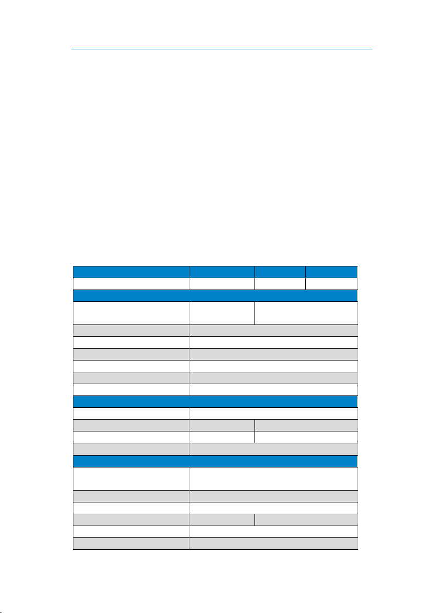
3Technical Specifications ..........................................................................3
4Unpacking the LPS...................................................................................5
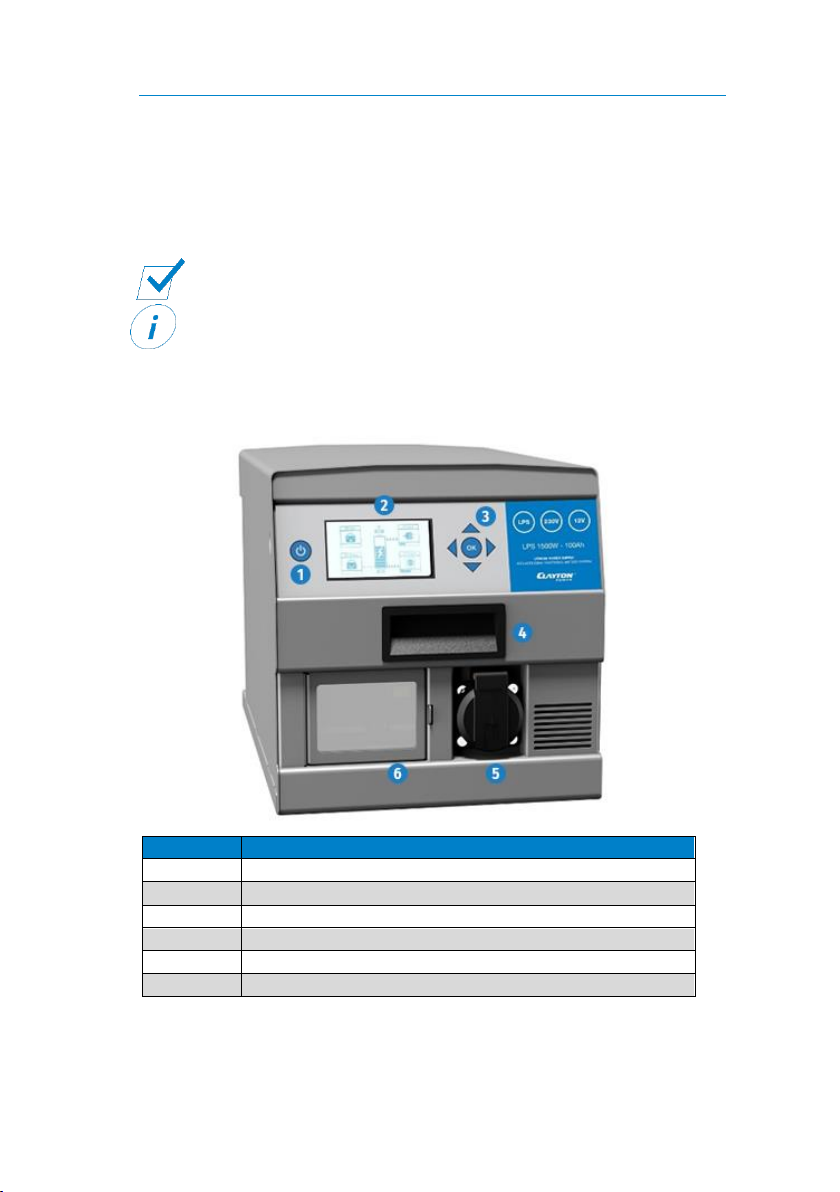
5About the LPS.......................................................................................... 5
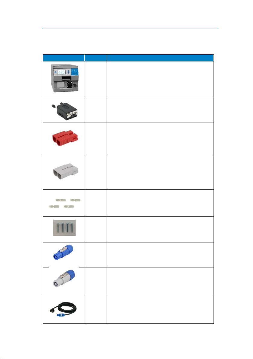
6Package Contents.................................................................................... 7
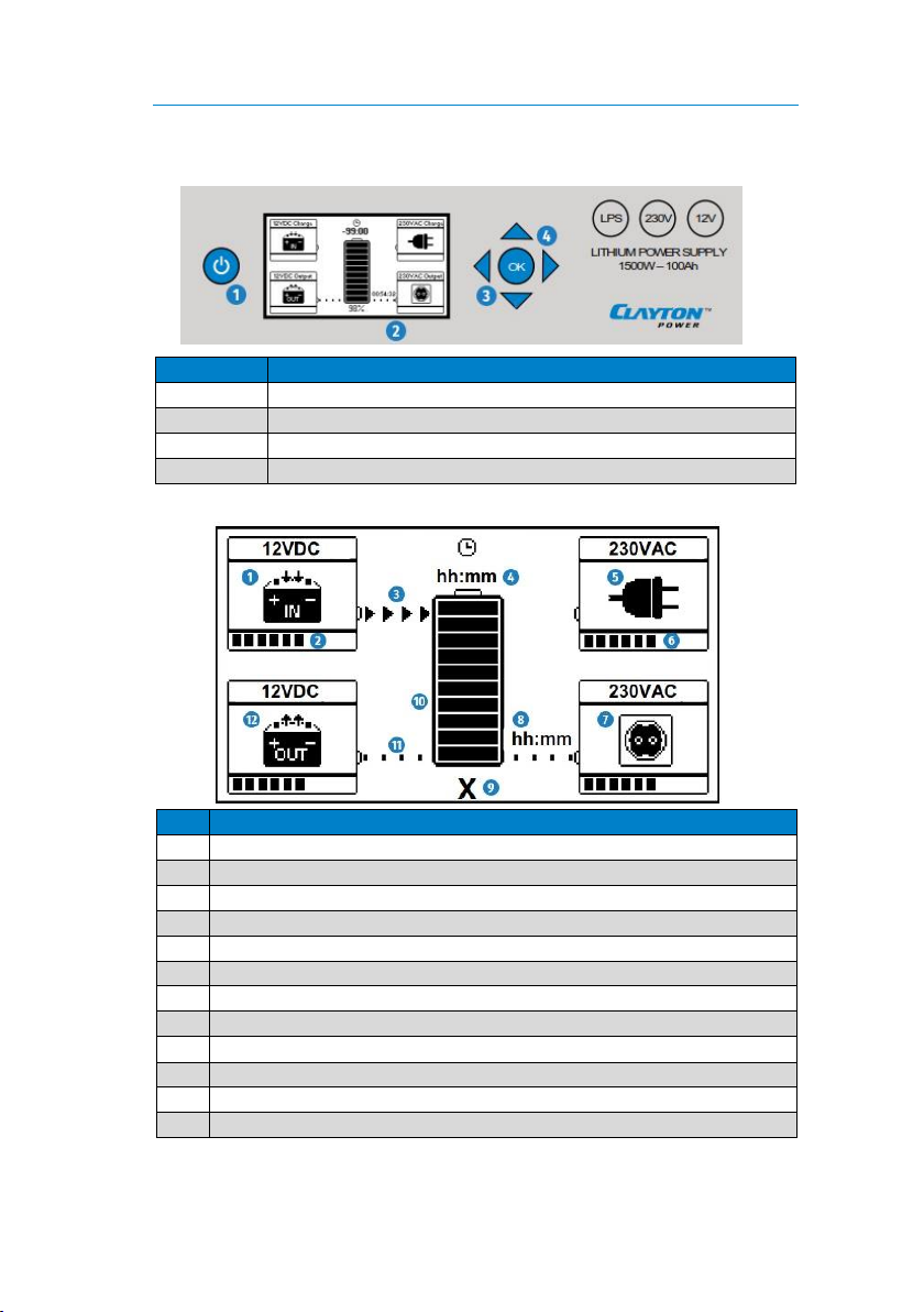
7Display..................................................................................................... 8
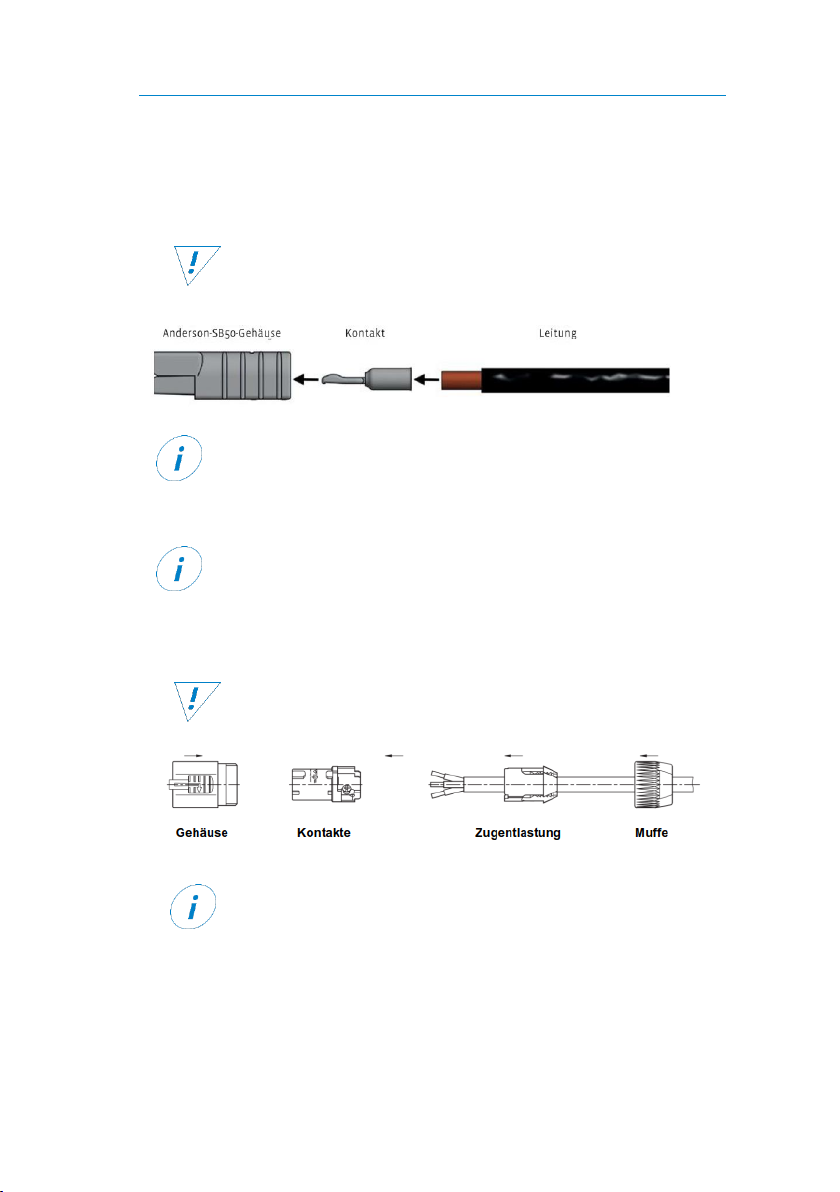
8Installing the Connection Set / Preparing Connections .......................... 9
9Mounting ..............................................................................................10
10 Installation ............................................................................................11
11 Installation of Accessories.....................................................................13
12 Operation.............................................................................................. 15
13 Displays ................................................................................................. 20
14 Maintenance.........................................................................................21
15 Troubleshooting....................................................................................22
16 Disassembly ..........................................................................................25
17 Disposal.................................................................................................25
18 EU Declaration of Conformity ............................................................... 25
1About this Manual
Read this manual carefully and keep it in a safe place. This manual is intended
for users with previous knowledge in the automotive electrical field.
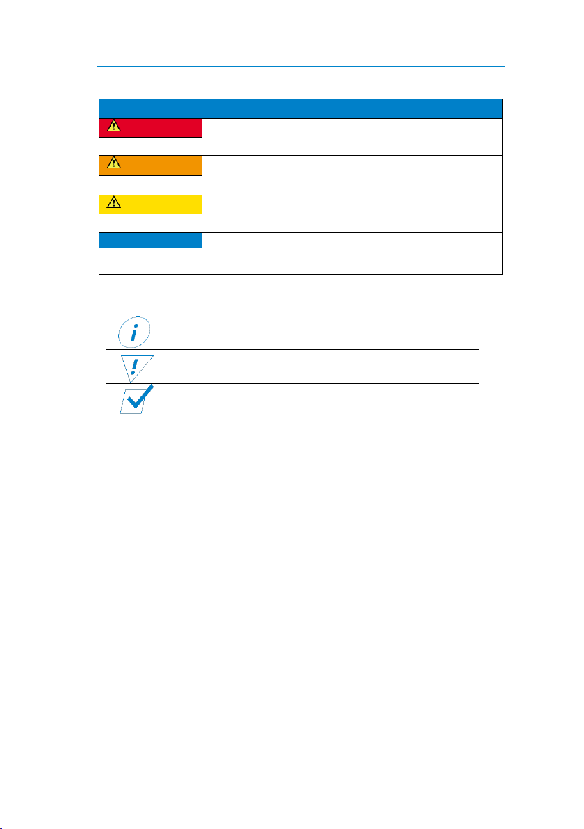
Throughout the manual, you will be alerted to warnings and safety notices
about potential hazards associated with handling the device. The colours and
signal words indicate the severity of the hazard:

Installation instructions General Safety
Page 2 of 25
Signal word
Meaning
DANGER
Warns of imminent danger resulting in death or serious
injury.
WARNING
Warns of a potentially dangerous situation that can
result in death or serious injury.
CAUTION
Warns of a potentially dangerous situation that can
result in moderate or minor injuries.
NOTICE
Warns of a potentially dangerous situation that can
result in material and environmental damage.
In this manual you will find the following symbols:
Shows you useful tips and information about the device.
Indicates a mandatory requirement for the following
instruction.
Shows the result of an instruction.
The information in this manual describes the factory settings of the device.
2General Safety
This manual supports safe handling of the device. Use the device solely in
accordance with its intended use:
The LPS is a high-quality product for mobile power supply in vehicles. All
components relevant for the power supply of the vehicle are integrated into
one device. This means that the LPS performs many functions that are
conventionally performed by individual components. The LPS supplies 12-V and
230-V consumers simultaneously via the integrated lithium-ion battery. When
the 230-V mains connection is inserted, the LPS is quickly charged via the built-
in charger. The connected 230-V consumers are automatically supplied by the
mains priority circuit via the 230-V mains.
Solar cells or alternative energy sources can also contribute to energy input.
Weak and discharged starter batteries can be supported with the optional
jumpstart function (emergency start).

Installation instructions Technical Specifications
Page 3 of 25
Any modifications to the device or its components are prohibited and do not
conform to its intended use.
The LPS is a protection class 1 device. Only connect the LPS to low-voltage
sources which have an earth connection (shockproof socket with PE) and a RCD
circuit breaker (FI).
Observe the following safety instructions:
Store and mount the LPS upright, never overhead or on its side.
Danger from damaged, frozen or deformed batteries: Before charging,
make sure that the battery is undamaged and the electrolyte is not frozen.
Only charge batteries in well-ventilated rooms and away from ignition
sources.
3Technical Specifications
Model
LPS 1212
LPS 1512
LPS 2512
Part number
014-02001GF
014-01004GF
014-03001GF
Device
Weight
(with/without packaging)
26 kg / 28 kg
28 kg / 30 kg
Dimension (device)
390 mm x 244 mm x 250 mm
Dimension (packaging)
495 mm x 355 mm x 350 mm
Protection class
I
IP rating
IP21
Operating temperature
-20°C … +50 °C
Cooling
Fan, active
Battery
Battery type
Lithium iron phosphate (LiFePO4)
Available capacity
48 Ah (634 Ah)
80 Ah (1056 Ah)
Rated value
60 Ah (792 Ah)
100 Ah (1320 Ah)
Cycle stability at 80%
2000 cycles
AC input
Voltage / frequency (rated
values)
230 V / 50 Hz
Voltage range
207 V …253 V
Frequency range
45 Hz …65 Hz
Current
2.5 A
3.5 A
Charging time
95 min
Connections
Neutrik PowerCon type A

Installation instructions Technical Specifications
Page 4 of 25
Model
LPS 1212
LPS 1512
LPS 2512
Part number
014-02001GF
014-01004GF
014-03001GF
AC output
Voltage / frequency (rated
values)
230 V / 50 Hz
Power (continuously)
1000 W
1300 W
2000 W
Power (mains priority circuit)
1800 W
1800 W
2300 W
Power (< 15 min)
1200 W
1500 W
2500 W
Power (< 10 s)
2400 W
3000 W
5000 W
Connections
Neutrik PowerCon type B, two-pin earthed
plug
DC input
Voltage (rated value)
12 V
Voltage range
12.8 V …15 V
Current
25 A
50 A
Charging time
105 min
Connection
Anderson SB50, grey
DC output
Voltage (rated value)
13.2 V
Voltage range
9.5 V …15 V
Current (continuous)
60 A
Current (< 20 min)
70 A
Current (< 1 min)
100 A
Current (< 10 s)
150 A
Connection
Anderson SB50, red
Performance data / operating periods
Internal consumption
(only DC active)
5 W
Internal consumption
(AC+DC active)
22 W
35 W
Internal consumption (Sleep)
0.025 W
Operating periods (200 W)
155 min
260 min
250 min
Operating periods (500 W)
65 min
110 min
105 min
Operating periods (1000 W)
35 min
55 min
55 min

Installation instructions Unpacking the LPS
Page 5 of 25
4Unpacking the LPS
To unpack the device, perform the following steps:
1. Lift the device out of the transport box using the black carrying handles on
the front and back.
The device is unpacked.
After unpacking, check the scope of delivery of the LPS (see page 7).
5About the LPS
Number
Details
1
On/Off button
2
Display
3
Control panel / navigation buttons
4
Carrying handle (front)
5
Two-pin earthed socket, AC output (230 V)
6
Fuse cap, RCD

Installation instructions About the LPS
Page 6 of 25
Number
Details
7
Carrying handle (back)
8
D-Sub plug for communications connections
9
AC output (230 V) Neutrik, grey
10
AC input (230 V), Neutrik, blue
11
DC output, (12 V) Anderson, red
12
DC input, (12 V) Anderson, grey

Installation instructions Package Contents
Page 7 of 25
6Package Contents
Figure
No.
Part Name
x 1
Lithium Power Supply (LPS)
x 1
D-Sub data adapter
x 1
Anderson plug SB50, red
x 1
Anderson plug SB50, grey
x 4
Contacts for Anderson SB50 plugs
x 4
4 x M3 screws for fastening the Anderson
plugs
x 1
Neutrik PowerCon type A plug, blue
x 1
Neutrik PowerCon type B plug, grey
x 1
Mains cable, Neutrik PowerCon type A with
two-pin earthed plug

Installation instructions Display
Page 8 of 25
7Display
Number
Item
1
On/Off button
2
Display
3
Arrow button
4
OK button
No.
Item
1
DC input (12 V)
2
Shows the charging capacity in 10 % increments
3
Shows the direction of the current flow
4
Shows the remaining operation (-hh:mm) or charging time (hh:mm)
5
AC input (230 V)
6
Shows the discharging capacity in 10 % increments
7
AC output (230 V)
8
Shows the remaining time until the output switches to Energy Saver
9
Shows the charge status of the battery in percent
10
Shows the charge status of the battery in 10 % increments
11
Shows the standby mode of the connection
12
DC output (12 V)

Installation instructions Installing the Connection Set / Preparing Connections
Page 9 of 25
8Installing the Connection Set / Preparing Connections
Anderson Plug
To mount the Anderson plug, observe the following notes:
For installation you need a H07V-K or equivalent electrical
cable with a cross-section of 16 mm² and a crimping tool.
Grey Anderson plug for DC input (12 V).
Red Anderson plug for DC output (12 V).
Notice: Reverse polarity may damage the device. Pay attention to the
polarity of the wires. The housing is marked with plus and minus.
Loosen and pull out incorrectly inserted cores using gentle lever
movements from a screwdriver (slot).
Mounting Neutrik Plug
To mount the Neutrik plug, observe the following notes:
For installation you need a H07RN-F 3G or equivalent
electrical cable with a cross-section of 1.5 mm².
blue Neutrik plug for AC input (230 V)
grey Neutrik plug for AC output (230 V)
white strain relief for cables with an average cross-section of
6 mm ... 11 mm
black strain relief for cables with an average cross-section of
9.5 mm ... 15 mm

Installation instructions Mounting
Page 10 of 25
Mounting the D-Sub Data Adapter
To mount the D-Sub data adapter, observe the following instructions:
You need an H07V-K or equivalent electrical cable with a
cross-section of 1 mm² and, if necessary, a fuse holder.
Pin
Item
Use
1
Single wire
Data transmission
2
CAN-Low
Software update
3
GND
Ground connection for
accessories
4
+12 V*
+12 V (active, if LPS active)
5
Input 2
External switching signal
(switching the inverter)
6
Output 1
CDR connection (jumpstart
function)
7
CAN-High
Software update
8
Output 2
Signal output**
9
Input 1
Activation of DC input after 10 s
connection D+ signal (terminal
15/terminal 61)***
* From hardware 2.02 (up to hardware 2.01: GND (ground))
** can be parametrised accordingly
*** Allocation necessary for installation at DC input
9Mounting
To mount the device, perform the following steps:
NOTICE
Choose a cool, dry and well-ventilated mounting site.
Mount the device on a flat surface.
Do not mount the device directly next to or above batteries or any
flammable materials
1. Fasten the device to the mounting location with screws on the underside
of the device or with the LPS mounting plate (optional accessory).
The device is mounted.

Installation instructions Installation
Page 11 of 25
10 Installation
Ensure that the LPS is switched off during installation.
Connecting the AC Input (230 V)
To install the device to the 230-V mains, perform the following steps:
1. Insert the blue Neutrik plug of the mains cable into the AC input (230 V)
on the device.
2. Turn the Neutrik plug clockwise until it clicks into place.
3. Plug the two-pin earthed plug into a 230-V mains supply.
The LPS starts the charging process automatically, consumers at the
AC output (230 V) are supplied with power via the 230-V mains
(mains priority circuit).
The device is connected.
Connecting the DC Input (12 V)
To connect the LPS to the vehicle battery, perform the following steps:
Grey Anderson plug is mounted.
1. Disconnect the battery from the vehicle power circuit.
Warning: Disconnect the negative cable first.
2. Secure the positive cable of the grey Anderson plug as close as possible to
the vehicle battery with a suitable fuse (80 A).
3. Connect the positive cable of the grey Anderson plug with the positive
terminal of the battery.
4. Connect the negative cable of the grey Anderson plug to the negative
terminal of the battery.
5. Connect a signal cable (1 mm²) to terminal 15 (switched ignition plus) or
terminal 61 (ignition signal) of the vehicle.

Installation instructions Installation
Page 12 of 25
6. Secure the signal cable near the connection to the vehicle with a suitable
fuse (1 A ... 3 A).
7. Connect the open end of the signal cable to pin 9 of the D-Sub data
adapter.
8. Connect the D-Sub data adapter to the D-Sub plug on the device.
9. Plug the grey Anderson plug into the DC input (12 V) on the device and
screw it tight.
10. Connect the vehicle battery with the vehicle power circuit.
The device is connected.
Connecting the Consumer AC Output (230 V)
You have two options for connecting consumers to the AC output (230 V).
Consumer with Neutrik plug:
Insert consumer with Neutrik plug into the AC output on the back of the
device.
A Neutrik plug is included. You will find information on how to
install the plug on page 9.
Consumer with two-pin earthed plug:
Plug consumer with two-pin earthed plug into the AC output on the front
of the device.
The consumer is connected.
Connecting the Consumer DC Output (12 V)
To connect consumers to the DC output (12 V), perform the following steps:
1. Insert the red Anderson plug of the consumer into the DC output of the
device.
An Anderson plug is included. You will find information on how to
install the plug on page 9.
The consumer is connected.

Installation instructions Installation of Accessories
Page 13 of 25
11 Installation of Accessories
Connecting Solar Panel
To charge the LPS with solar panels, perform the following steps:
You need a solar charge controller with Maximum Power
Point Tracking (MPPT) and an output voltage (DC) of 14.5 V ...
15 V.
You have mounted the red Anderson plug.
1. Connect the solar controller with the red Anderson plug.
2. Connect the solar charge controller to the photovoltaic cells.
For the installation of the solar charge controller, follow the notes
and instructions in the device manual.
3. Insert the red Anderson plug into the DC output (12 V).
4. Activate the DC output (12 V) via the menu of the LPS (see page 18).
The solar panel is connected.
Connecting Fuel Cells
To charge the LPS using alternative charging sources (fuel cells), perform the
following steps:
You have mounted the red Anderson plug.
1. Connect the fuel cell with the red Anderson plug.
For the installation of the fuel cell, follow the notes and instructions
in the device manual.
2. Insert the red Anderson plug into the DC output (12 V).
3. Activate the DC output (12 V) via the menu of the LPS (see page 18).
The fuel cell is connected.

Installation instructions Installation of Accessories
Page 14 of 25
Connecting the CDR Power Distributor Relay
The LPS has a jumpstart function to start the vehicle when the starter battery is
discharged. In an emergency, the CDR power distributor relay ensures
controlled and current-limited charge compensation between the LPS and the
empty starter battery.
From hardware version 12.20/15.20/25.20, the jumpstart function
is also possible without CDR.
To connect the CDR power distributor relay, perform the following steps:
You need a CDR 200/40.
You need two cables (16 mm2).
1. Disconnect the starter battery from the on-board power supply.
Warning: Disconnect the negative lead first.
2. Secure one cable (16 mm2) of the device near the vehicle battery with a
suitable fuse (80 A).
3. Using the fused line, connect the positive terminal of the vehicle battery
to a screw terminal of the CDR.
4. Use a cable to connect the same screw terminal of the CDR with the
positive contact of the grey Anderson plug.
5. Use a cable to connect the negative terminal of the vehicle battery to the
negative contact of the grey Anderson plug.

Installation instructions Operation
Page 15 of 25
6. Use a cable to connect the other screw terminal of the CDR to the positive
contact of the red Anderson plug.
7. Connect the ground wire (black) and bridging wire (blue) of the CDR to
pin 6 of the D-Sub data adapter.
8. Insert the D-Sub data adapter into the D-Sub plug of the LPS.
9. Insert the grey Anderson plug into the DC input (12 V) and screw the
Anderson plug tight.
10. Insert the red Anderson plug into the DC output (12 V) and screw the
Anderson plug tight.
The CDR is connected.
Connecting the LPS Remote Display
If the LPS is installed such that the display is not visible, an LPS remote display
from LEAB can be connected to control the LPS.
To install the remote display, follow the notes and instructions in
the manual.
12 Operation
Switching on the LPS
To switch on the LPS, perform the following step:
1. Press the On/Off button to switch on the LPS.
The display will light up.
The LPS is switched on.
Charging the LPS (230 V, AC)
To charge the LPS with 230 V, perform the following steps:
Blue Neutrik plug is mounted.
1. Plug the two-pin earthed plug of the mains cable into a 230-V mains
supply.
The charging process starts automatically.
Display is activated.
The factory-set mains priority circuit supplies the connected 230-V
consumers via the 230-V mains.
The LPS is charged.

Installation instructions Operation
Page 16 of 25
Limiting Input Current (230 V, AC)
The LPS gives you the option to control the input current of the AC input,
adjustable values are between 1 A and 10 A. To limit the input current at the
AC input, perform the following steps:
1. Press the OK button to access the menu.
2. Select the menu item '230VAC Charging' by pressing the arrow buttons
(up/down) and confirm selection by pressing the OK button.
3. Select the menu item 'Maximum Current' by pressing the arrow buttons
(up/down) and confirm selection by pressing the OK button.
4. Select the desired current limit value by pressing the arrow buttons
(up/down) and confirm selection by pressing the OK button.
5. To exit the menu, press the left arrow button twice.
The input current is limited.
Activate/Deactivate 230-V Output
To activated or deactivate the 230-V output, perform the following steps:
1. Press the On/Off button to open the On/Off menu.
2. Select the menu item 'AC Out' by pressing the arrow buttons (up/down).
The following icons are displayed:
AC output is active
Mains priority circuit is active
AC output is inactive
3. To change the setting, press the OK button.
4. To exit the On/Off menu, press the left arrow button.
The 230-V output is activated or deactivated.
Device is ready for operation.

Installation instructions Operation
Page 17 of 25
Deactivate/Activate Energy Saver (230 V, DC)
The Energy Saver is used to set a threshold and a time. If the value falls below
this threshold, the set time runs down and the AC output (230 V) is
automatically deactivated after the time has elapsed.
To activated or deactivate the Energy Saver, perform the following steps:
1. Press the OK button to access the menu.
2. Select the menu item '230VAC Output' by pressing the arrow buttons
(up/down) and confirm selection by pressing the OK button.
3. Select the menu item 'Energy Saver (Threshold)' by pressing the arrow
buttons (up/down) and confirm selection by pressing the OK button.
4. In order to activate the Energy Saver, select a value between 0 W and
200 W by pressing the arrow buttons (up/down) and confirm selection by
pressing the OK button.
5. To exit the menu, press the left arrow button.
6. Select the menu item 'Energy Saver (No Load)' by pressing the arrow
buttons (up/down) and confirm selection by pressing the OK button.
7. In order to activate the Energy Saver, select a time between 1 min …10 h
by pressing the arrow buttons (up/down) and confirm selection by
pressing the OK button.
8. To deactivate the Energy Saver, press the down arrow button until
'inactive' is displayed and confirm the selection with the OK button.
9. To exit the menu, press the left arrow button twice.
The Energy Saver is activated or deactivated.
Charging the LPS (12 V, DC)
The LPS is automatically charged with 12 V when a voltage is applied to the
DC input and a signal is applied to the D-Sub connector.
If there is no signal at the D-Sub connector or no voltage, the LPS is
not charged.
The device is switched on.

Installation instructions Operation
Page 18 of 25
Activate/Deactivate 12-V Output
To activated or deactivate the 12-V output, perform the following steps:
1. Press the On/Off button to open the On/Off menu.
2. Select the menu item 'DC Out' by pressing the arrow buttons (up/down).
DC output is active
DC output is inactive
3. To change the setting, press the OK button.
4. To exit the menu, press the left arrow button.
The 12-V output is activated or deactivated.
Activate Jumpstart Function (Emergency Start) (12 V, DC)
With the help of the jumpstart function (emergency start), a discharged starter
battery can be jumpstarted by the LPS to such an extent that a starting process
is possible again.
To activate the jumpstart function, perform the following steps:
1. Press the OK button to access the menu.
2. Select the menu item '12VDC Output' by pressing the arrow buttons
(up/down) and confirm selection by pressing the OK button.
3. Select the menu item 'Jumpstart' by pressing the arrow buttons
(up/down) and confirm selection by pressing the OK button.
4. To activate the jumpstart function, press the OK button.
A charging current of 40 A is provided for 5 min at the DC input.
After 5 minutes, the vehicle can be started as usual.
5. To exit the menu, press the left arrow button twice.
The jumpstart function is activated.
Device is ready for operation.
The device is switched on.
A CDR was installed (before HW version 12.20/15.20/25.20 , s.
page 14)

Installation instructions Operation
Page 19 of 25
Deactivate/Activate Shutdown Delay (12 V, DC)
With the shutdown delay you have the option to delay the deactivation of the
DC output until after switching off the LPS.
To activate or deactivate the shutdown delay, perform the following steps:
1. Press the OK button to access the menu.
2. Select the menu item '12VDC Output' by pressing the arrow buttons
(up/down) and confirm selection by pressing the OK button.
3. Select the menu item 'Shutdown Delay' by pressing the arrow buttons
(up/down) and confirm the selection by pressing the OK button.
4. To activate the shutdown delay, select a time of 1 min ... 10 h by pressing
the arrow buttons (up/down) and confirm the selection by pressing the
OK button.
5. To deactivate the shutdown delay, press the lower arrow button until
'inactive' is displayed and confirm the selection with the OK button.
6. To exit the menu, press the left arrow button twice.
The shutdown delay is activated or deactivated.
Switch Off LPS
To switch off LPS, perform the following steps:
1. Press the On/Off button.
An On/Off menu opens.
2. Press the OK button to confirm the 'Shutdown' menu item and switch off
the LPS.
The LPS cannot be completely switched off when charging is taking
place at the AC input (230 V) or DC input (12 V).
The LPS is switched off.
The device is switched on.
This manual suits for next models
3
Table of contents
Other LEAB Power Supply manuals
Popular Power Supply manuals by other brands

Powerfinn
Powerfinn PAP3200HV operating manual

Elmdene
Elmdene G1380 BMU Series quick start guide

Belden
Belden Hirschmann PC150/36V/48V-IP67 Description and operating instructions

Extron electronics
Extron electronics EPS 1210 P Specification sheet

Black Box
Black Box PS568A user manual

Aube Technologies
Aube Technologies Power Base PB1 30-024T installation instructions