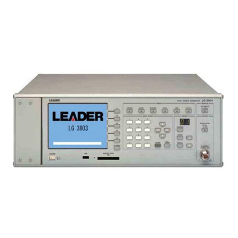
Leader Electronics Corp. LT 416 User manual

LT 416
INSTRUCTION MANUAL
NTSC/PAL/SECAM
PATTERN GENERATOR

TABLE OF CONTENTS
GENERAL SAFETY SUMMARY ···························································································· |
1. INTRODUCTION ··············································································································1-1
1.1 Scope of Warranty ······························································································1-2
1.2 Operating Precautions ·······················································································1-2
1.2.1 Line Voltage and Fuse ························································································1-2
1.2.2 Reverse Voltage···································································································1-2
1.2.3 Installation ···········································································································1-2
1.2.4 Mechanical Shock ·······························································································1-3
1.2.5 Calibration ···········································································································1-3
1.2.6 Routine Maintenance··························································································1-3
2. SPECIFICATIONS ············································································································2-1
2.1 GENERAL ············································································································2-1
2.2 FEATURES ···········································································································2-1
2.3 Specifications······································································································2-2
2.3.1 Composite Video Signal Output ········································································2-2
2.3.2 Sync Signal··········································································································2-3
2.3.3 Test Patterns········································································································2-4
2.3.4 Y/ C Separation Output·······················································································2-5
2.3.5 Y, B-Y, R-Y Output ·······························································································2-5
2.3.6 R, G, B Output ·····································································································2-6
2.3.7 RF Output·············································································································2-6
2.3.8 Sound Output ······································································································2-7
2.3.9 General Specifications ·······················································································2-7
3. PANEL DESCRIPTION ····································································································3-1
3.1 Front Panel ··········································································································3-1
3.2 Rear Panel············································································································3-3
4. OPERATING PROCEDURE·····························································································4-1
4.1 Turning Power On ·······························································································4-1
4.1.1 Connecting Power Plug······················································································4-1
4.1.2 Turning Power On ·······························································································4-1
4.1.3 Warm-Up Time·····································································································4-1
4.2 Connection ··········································································································4-1
4.2.1 Cable ····················································································································4-1
4.2.2 Termination··········································································································4-2
4.3 Color System Selection······················································································4-2
4.4 Composite Video Signal·····················································································4-3
4.4.1 Variable VIDEO OUTPUT connector·································································4-3
4.4.2 Fixed VIDEO OUTPUT Connector······································································4-3

4.5 Component Video Signal····················································································4-3
4.5.1 Y, B-Y, R-Y Connectors ⑲··················································································4-3
4.5.2 R, G, B, C.SYNC Connectors ⑳·········································································4-3
4.6 Y/C Separation Signal·························································································4-4
4.6.1 Y/C OUTPUT Connector ·····················································································4-4
4.7 Audio Signal ········································································································4-4
4.7.1 AUDIO OUTPUT Connector················································································4-4
4.8 RF Signal ·············································································································4-4
4.8.1 OUTPUT Connector ⑱························································································4-4
4.8.2 Level knob ···········································································································4-4
4.9 Pattern Settings···································································································4-4
4.10 RF Channel Settings···························································································4-5
4.10.1 Setting Method ····································································································4-5
4.10.2 Setting Procedure ·······························································································4-6
4.10.3 Selecting Channel·······························································································4-7
4.10.4 Restriction by 「SYSTEM ⑨」············································································4-7
4.10.5 RF Modulation ·····································································································4-7
4.10.6 RF Setting Example ····························································································4-8
4.10.7 Sound Subcarrier Level Selection·····································································4-8
4.11 Battery Backup····································································································4-9
4.11.1 Backup Capability ·······························································································4-9
4.11.2 Battery··················································································································4-9
4.11.3 Battery Life ··········································································································4-9
4.12 Fuse Replacement ······························································································4-9
5. RF CHANNEL PLAN········································································································5-1
5.1 Broadcast System·······························································································5-1
5.2 Broadcast System/Channel Plan for Country/ Region ····································5-1
5.3 Channel Plan Table ·····························································································5-7
5.3.1 How to use Channel Plan Table ·········································································5-7
5.3.2 Channel Plan Table ·····························································································5-8
6. MAINTENANCE ···············································································································5-20

— I —
The sections where this symbol is marked in this manual or
instrument, if not correctly performed or practiced, could result in
personal injury or cause serious danger to the instrument. Misuse
could also produce unintentional movement to create an
operational impediment on the instrument or other products that
might be connected to it.
Be sure to refer to the safety precautions in this manual to safely
use the part of the instrument where the symbol is marked.
Warning statements identify warning conditions that if
disregarded
or not correctly performed or adhered to, could result in serious
personal injury or even loss of life.
Caution statements identify caution conditions that if disregarded
or not correctly performed or adhered to, could result in personal
injury or damage to the instrument.
<Symbol>
<Te r m >
<Te r m >
WARNING
CAUTION
GENERAL SAFETY SUMMARY
■To Avoid Personal Injury
It is recommended that only qualified personnel with technical knowledge use this
instrument only after reading and fully understanding all functions of the instrument
described this instruction manual.
This instrument is not designed and manufactured for consumers.
If you do not have enough knowledge on electricity, to avoid personal injury and
prevent damage to this product, please be sure to use this product only under the su-
pervision of an engineer who has sufficient knowledge about electronics.
■Precautions on Contents
Should you find the contents in this manual and any of its technical terms confusing,
please feel free to contact your local LEADER agent.
■Symbols and Terms
Following terms and symbols indicate necessary warnings and cautions used in this
manual and on the product are there for safe operation.

— II —
WARNING
GENERAL SAFETY SUMMARY
Review the following safety precautions to avoid operator's injury and loss of life
and prevent damage and deterioration to this instrument. To avoid potential hazards, use
this product as specified.
■Warnings on the Cases and Panels of the Instrument
Operator should not remove any cases or panel for any reasons. If you touch
inside the instrument it could result personal shock or fire hazard. Refrain
from spilling any liquid on or inserting anything flammables or piece of metal
into the ventilation of the instrument. Such actions could cause fire, shock,
malfunction and be an accident hazard while the power is on.
■Warnings on Power Line
●Make sure to connect only to the rated power line voltage. Excess
voltage may cause fire.
Confirm the voltage of the commercial power line before connecting the AC power
cord. The power frequency of the power line should be 50/60 Hz.
●Warning on the Power Cord
Use only the optional power cord that is attached to this instrument. The use of the
power cord other than that attached could cause fire hazard.
If the attached cord is damaged stop using it and contact your local LEADER
agent. Should you use a damaged cord, it could cause a shock or create a fire
hazard. When you pull out the cord be sure to hold it by plug and pull from the
socket not by holding the cord wire.
■Warning on Fuse
When the fuse is melted the instrument stops operation. If the fuse melted, turn off the
power switch and disconnect the power plug from the socket. If you change the fuse
while the cord is connected to the socket, it could cause a shock hazard. Only use the
specified type and rated current and voltage fuses.
If the cause for melting fuse is unclear or if you suspect there is damage to the instru-
ment or if you have no proper fuse at hand please contact your local LEADER
agent.

— III —
WARNING
GENERAL SAFETY SUMMARY
■Warning on Installation Environments
●About the Operating Temperature Range
Operate the instrument between the temperature range of 0 to 40 °C. Operating the
instrument at higher temperatures could cause a fire hazard.
Rapid changes of temperatures from cold to warm can create internal moisture or
condensation and could damage the instrument. If there is a possibility of moisture
condensation allow the instrument to sit for 30 minutes without the power on.
●About the Operating Humidity Range
Operating humidity range is ≤90 % RH.
Do not operate the instrument with wet hands. This could cause a shock and fire
hazard.
●About the Operation in the Presence of Gasses
Operating the instrument in and near the presence or storage locations of flam-
mable, explosive gasses or fumes could create an explosion and fire hazard. Do not
operate the instrument anywhere near such environments.
●Avoid Insertions
Do not insert metals or flammable objects or drop liquid on or into the instrument.
To do so could cause fire, shock, malfunction and create a dangerous accident haz-
ard.
■Warning while Operating
While operating the instrument if smoke, fire, or a bad smell occurs, turn off the instru-
ment at once for it could cause a fire hazard. When such a case occurs, turn off the
power switch and pull the plug of the cord from the plug socket. Contact your local
LEADER agent after confirming there is no fire.
■Warning about Ground
The instrument has a ground terminal to avoid electric shock hazard and to protect the
instrument from damage. Ensure that the product is properly grounded for safe opera-
tion.

— IV —
CAUTION
■Caution when Not to Use the Instrument for a Long Time
Make sure to disconnect the power cord from the socket when you do not use the
instrument for a long time.
GENERAL SAFETY SUMMARY
■Caution on Input/Output Terminals
Input Terminals are rated with a maximum input. Do not supply an input over the
specified rating in the standard section of the instruction manual. Also, do not supply
external power to Output terminal, this could cause the instrument to malfunction.
Please conform to the above warnings and cautions for safe operation. There are cautions
in each area of this instruction manual, so please conform to each caution. If you have any
questions about this manual, please feel free to contact your local LEADER agent.

1. INTRODUCTION
Thank you for purchasing Leader’s measuring instruments.
Please read this instruction manual carefully to ensure correct and safe operation.
If you have any difficulties or questions on how to use the instrument after you have read this
manual, please feel free to contact your local LEADER agent.
1.1 Scope of Warranty
This LEADER instrument has been manufactured under the strictest quality control
guidelines.
LEADER shall not be obligated to furnish free service during the warranty period under the
following conditions.
1. Repair of malfunction or damages resulting from fire, natural calamity, or improper
voltage applied by the user.
2. Repair of an instrument that has been improperly repaired, adjusted, or modified by
personnel other than a factory-trained LEADER representative.
3. Repair of malfunctions or damages resulting from improper use.
4. Repair of malfunctions caused by devices other than this instrument.
5. Repair of malfunctions or damages without the presentation of a proof of purchase or
receipt bill for the instrument.
1-1

CAUTION
1.2 Operating Precautions
WARNING
1.2.1 Line Voltage and Fuse
Confirm that the power line voltage is correct before connecting the power cord.
The voltage range and fuse rating are indicated on the rear panel.
When replacing the fuse, turn the power switch off and disconnect the power cord
from the mains.
Voltage Range Fuse
Rating LEADER Parts Number
90 to 250 V T0.63AL, time-lag 436 3555 005
1.2.2 Reverse Voltage
•Shorting the output connectors
Do not short any output connectors to prevent damage to the instrument.
•Do not apply external voltage to the output connectors. It can cause trouble.
1.2.3 Installation
Do not use the instrument in the following environments.
•High temperature environments
Do not place the instrument under direct sunlight or near a heater (e.g., stove).
Do not move the instrument from cold to warm environment abruptly, it may cause
condensation.
Operating temperature range: 0 to 40 °C
•High humidity environments
Do not place the instrument in the high humidity environment (e.g., bathroom, near
a humidor).
Operating humidity range: ≤90 % RH
•Dusty environments
1-2

1.2.4 Mechanical Shock
Please be careful not to expose the instrument to other forms of severe mechanical
shock as this product contains shock sensitive precise parts.
1.2.5 Calibration
When calibration or service is required, contact your local LEADER agent.
1.2.6 Routine Maintenance
When cleaning the instrument, do not use such solvents as thinner or benzol which
will remove paint or damage the plastic surface. Use a soft cloth dampened with
neutral detergent.
Do not drop water or detergent, or insert metal object into the instrument while
cleaning. Otherwise, you run the risk of electrical shock or fire.
1-3

2. SPECIFICATIONS
2.1 GENERAL
Model LT 416 is a precision test-signal source which provides four color systems of
NTSC, PAL, SECAM, and NTSC-4.43 for testing and adjusting all kind of video
products such as TV, VTR etc.
In addition of a composite signal output, the generator provides a Y/C output and a
component signal outputs (except SECAM) of Y/B-Y/R-Y and GBR so that it is
suitable to a production line for video products of component system.
RF output is easily selected by setting channel number while the channels are pre-
programmed by each countries.
15 test patterns including color bars, raster, convergence and circle satisfy the most
desired applications.
2.2 FEATURES
•Conforms to four standards (i.e., NTSC, PAL, SACAM, NTSC-4.43)
This generator is ideal for adjusting and testing TVs, VTRs, and AV equipments.
•Sconnector
An S connector is provided to output Y and C signals for adjusting AV equipments
with S connector.
•Component video signal output
This generator outputs the composite video signal and component video signal.
Since Y/ B-Y/ R-Y or G/ B/ R is output, the generator allows test signals for
component AV system adjustment and testing. (The SECAM color signals
(B-Y, R-Y) are not output.)
•RF setting
The channel plan based on the country system is provided for easier RF frequency
setting.
•Various test patterns
The 15 patterns including color bar and circle are provided for various adjustment
and test processes.
2-1

2.3 Specifications
2.3.1 Composite Video Signal Output
(1) Color System: NTSC, PAL, SECAM, NTSC-4.43
(2) Scanning Method
NTSC/ NTSC-4.43: 525-line interlace scanning
PAL/ SECAM: 625-line interlace scanning
(Progressive scanning can be performed for all color systems when the
CIRCLE or CONVERGENCE pattern is selected.)
(3) Field frequency
NTSC: 59.94 Hz ±30 ppm
(60.06 Hz ±30 ppm for progressive
scanning)
PAL/ SECAM: 50 Hz ±30 ppm
(50.08 Hz ±30 ppm for progressive
scanning)
NTSC-4.43: 59.94 Hz ±150 ppm
(60.06 Hz ±150 ppm for progressive
scanning)
(4) Line frequency
NTSC: 15.734 kHz ±30 ppm
PAL/ SECAM: 15.625 kHz ±30 ppm
NTSC-4.43: 15.734 kHz ±150 ppm
(5) Subcarrier Frequency
NTSC: 3.579545 MHz ±30 ppm
PAL: 4.43361875 MHz ±30 ppm
NTSC-4.43: 4.43361875 MHz ±50 ppm
(Progressive scanning can be selected when
CIRCLE or CONVERGENCE patterns is
selected.)
(6) Video Generating System: Digital system using 4 fsc sampling (without
SECAM)
(7) Number of Quantitative Bits: 8 bits
(8) Output Impedance: 75Ω
(9) Output Level: 1 Vp-p ±50 mVp-p (Between sync tip and
100 % white)
0 to 1 Vp-p, continuous variable
2-2

(10) Setup Level: NTSC: 0 % (“7.5 %” model optionally
available)
PAL/SECAM/NTSC 4.43 : 0 %
(11) Output connector
Variable output: BNC
Fixed output: RCA jack ............. 1
(12) Number of Outputs: 1 each ................. 1
2.3.2 Sync Signal
(1) Sync Signal
Amplitude
NTSC/ NTSC-4.43: 286 mVp-p ±14 mVp-p
PAL/ SECAM: 300 mVp-p ±15 mVp-p
Horizontal Sync Width: 4.7 µs ±200 ns (same spec.)
Vertical Sync Width
NTSC/ NTSC-4.43: 3H
PAL/ SECAM: 2.5H
Vertical Blanking Period
NTSC/ NTSC-4.43: 20H
PAL/ SECAM: 25H
(2) Color Burst
Amplitude
NTSC/ NTSC-4.43: 286 mVp-p ±23 mVp-p
PAL: 300 mVp-p ±24 mVp-p
Number of Cycles
NTSC: 9 cycles
PAL: 10 cycles
NTSC-4.43: 11 cycles
(3) SECAM Color Identification Signal
Amplitude
D’R Line: 540 mVp-p +40 mVp-p, -50 mVp-p
D’B Line: 500 mVp-p ±50 mVp-p
(4) SECAM Color (Back porch on the horizontal blanking period)
Amplitude
D’R Line: 215 mVp-p ±25 mVp-p
D’B Line: 167 mVp-p ±20 mVp-p
2-3

2.3.3 Test Patterns
(1) Color Bar: 100/ 0/ 75/ 0 Full-field Color Bar
(2) Demodulator Pattern (Not output when the SECAM is selected)
PAL: Combination of normal and reversed B-Y
and R-Y for each line
NTSC: Combination of normal and reversed B-Y,
R-Y, I, and Q for each line
line n: R-Y, -(R-Y), B-Y, -(B-Y), R-Y, -(R-Y), B-Y,
-(B-Y)
line n+1: -(R-Y), R-Y, B-Y, -(B-Y), R-Y, -(R-Y),-(B-Y),
B-Y
line n: I, -I, Q, -Q, I, -I, Q, -Q
line n+1: -I, I, Q, -Q, I, -I, -Q, Q
(3) Multiburst
Frequency
NTSC/ NTSC-4.43: 0.5, 1.0, 2.0, 3.0, 3.58, 4.2 MHz
PAL/ SECAM: 0.5, 1.0, 2.0, 4.0, 4.8, 5.5 MHz
Amplitude: 100 %(*)
(4) Raster
Output eight colors in combination with red, green and, blue
Color: 100 % white, yellow, cyan, green, magenta, red, blue, black
Amplitude: Same as color bars
(5) Window
Window Amplitude: 100 %(*)
(6) Step
10 equal steps from 0 mV to 700 mV white
(7) Circle Pattern: White circle pattern (with black fringe) on the
convergence pattern
Color Burst: on/off selectable
Interlace/ Progressive: Selectable
(Flicker may occur on the border of convergence and circle patterns.)
(8) Convergence
Luminance Amplitude: 75 %(*)
Number of Vertical Lines
NTSC/ NTSC-4.43: 17
PAL/ SECAM: 19
2-4

Number of Horizontal Lines
NTSC/ NTSC-4.43: 14
PAL/ SECAM: 15
Horizontal Line Width: 2 lines
Number of Dots
NTSC/ NTSC-4.43: 16 x 13
PAL/ SECAM: 18 x 14
Dot Pulse Vertical Width: 2 lines
Color Burst: On/ off selectable
Interlace/ Progressive: Selectable
(*) Notes on pattern specifications
Signal amplitude (100 %) is as follows.
PAL/ SECAM: 700 mVp-p
NTSC/ NTSC-4.43: 714 mVp-p
Accuracy: Same as the composite signal
2.3.4 Y/ C Separation Output
Specifications: Same as the composite signal
Output Impedance: 75 Ω
Connector: S type
Number of Outputs: 1
2.3.5 Y, B-Y, R-Y Output
Output Signal (*2): Y, B-Y, R-Y
Y Output Amplitude
NTSC/ NTSC-4.43: 714 mVp-p ±36 mV
PAL: 700 mVp-p ±35 mV
Sync Signal Amplitude
NTSC/ NTSC-4.43: 286 mVp-p ±14 mV
PAL: 300 mVp-p ±15 mV
B-Y, R-Y Output Amplitude: 525 mVp-p ±26 mV
Output Impedance: 75 Ω
Connector: BNC
Number of Outputs: 1 each
(*2) B-Y and R-Y are output when the SECAM is selected;
Y is only output.
2-5

2.3.6 R, G, B Output
Output Signal (*3): R, G, B, C.SYNC
R, G, B Output Amplitude: 700 mVp-p ±35 mV (NTSC, PAL,
NTSC-4.43)
C.SYNC Output Amplitude: C-MOS Level (NTSC, PAL, SECAM,
NTSC-4.43)
Output Impedance: 75 Ω
Connector: BNC
Number of Outputs: 1 each
(Pulse noise may be superimposed n the leading and trailing edges of the R, G
and B Sync signals.)
(*3) R, G, B are output when the SECAM is selected;
C.SYNC is only output.
2.3.7 RF Output
System
NTSC: M
PAL: B, D, G, H, I, K
SECAM: B, D, G, H, K, L
(The RF is disabled when the NTSC-4.43 is selected)
Carrier Frequency Range: VHF and UHF
Carrier Frequency Setting Method: Direct setting using programmed country
channel plan (Arbitrary frequency cannot be
set)
Modulation Polarity: Negative or Positive
Modulation System: Double sideband
Sound Signal
Intercarrier Frequency: 4.5, 5.5, 6.0, 6.5 MHz
Modulation Signal: 1 kHz ±200 Hz
Modulation System: FM or AM
Output Voltage
VHF: At least 1 mVrms (into 75 Ω)
UHF: At least 0.5 mVrms (into 75 Ω)
Number of Output: 1 (75 Ω, BNC)
Since a double sideband modulation system is used for the RF signal of the LT 416.
such parameters as P/S ratio do not conform to the official standards.
Therefore, video noise or audio noise may appear on a TV monitor, etc. when the RF
signal of the LT 416 is applied.
2-6

2.3.8 Sound Output
Output Signal: 1 kHz ±100 Hz, sine wave
Amplitude: 1.2 Vp-p (into 600 Ω)
Output Impedance: 600 Ω
Number of Output: 1 (RCA jack)
2.3.9 General Specifications
Environmental Conditions
Operating Temperature: 0 to 40 °C
Operating Humidity: ≤90 % RH (without condensation)
Spec-Guaranteed Temperature: 10 to 30 °C
Spec-Guaranteed Humidity: ≤85 % RH (without condensation)
Operating Environment: Indoor use
Operating Altitude: Up to 2000 m
Overvoltage Category: ΙΙ
Pollution Degree: 2
Power Requirements: 90 to 250 VAC, 50/ 60 Hz Max.15 W
Dimensions: 426 (W) x 88 (H) x 300 (D) mm
(excluding projections)
Weight: 4.6 kg
Accessories: Power cord .............................. 1
Instruction manual ................... 1
2-7

3. PANEL DESCRIPTION
Please refer to each item number described on Figure 3-1 and 3-2 for the described
instruction after 4.OPERATING PROCEDURE.
3.1 Front Panel
Figure 3-1 Front Panel
qPOWER switch
Push this switch in to apply power. Release this switch for turning power off.
wPattern keys
Select the pattern.
eR, G, B keys
Set raster color when the raster pattern is selected. Eight colors can be set in
combination with the keys pressed.
rPROGRESSIVE/ INTERLACE key
Select the scanning system when “CIRCLE” or “CONVERGENCE” is selected
by using the “Pattern Keys w.”
When the PROGRESSIVE is selected, the key LED light. When the INTERLACE
is selected, the key LED goes off.
tBURST key
Selects the color burst on or off when “CIRCLE” or “CONVERGENCE” is
selected by using the “Pattern Keys w.” When the signal with color burst is
output, the key LED lights; when the signal without color burst is output, the key
3-1
qwuio!3 !4 !6 !7
ert y!0 !1 !2 !5 !8

LED goes off.
In the SECAM system, this key is used to turn on or off the reference burst.
y COUNTRY/ CHANNEL u CHANNEL/ COUNTRY display i SELECT keys
This block is used to control the RF frequency.
Press the COUNTRY/ CHANNEL ywhen selecting the TV channel number and
country number.
When the COUNTRY LED light, the country number being selected is displayed
on the CANNEL/ COUNTRY display u.
When the CHANNEL LED light, the TV channel being selected is displayed on
the CHANNEL/ COUNTRY display u.
Use the SELECT ito select the country number and channel number.
The COUNTRY/ CHANNEL yis also used to turn on or off the sound subcarrier
on the RF output.
oSYSTEM
Selects the color system.
!0 AUDIO OUTPUT connector
Outputs 1 kHz sine wave in fixed level.
RCA jack is used. Output impedance is 600 Ω.
!1 VIDEO OUTPUT connector
Outputs composite video signal in fixed level.
RCA jack is used. Output impedance is 75 Ω.
!2 Y/C OUTPUT connector
Outputs Y and C video signals in fixed level.
S connector is used. Output impedance for both Y and C is 75 Ω.
!3 VIDEO OUTPUT !4 LEVEL !5 OUTPUT
This group is used to control the composite video signal output level.
OUTPUT connector is BNC, and output impedance is 75 Ω.
The level is calibrated at the PRESET (detent) position.
The output level can be set from 0 V (MIN, immediately before the detent
position) to the preset level (MAX) by rotating the OUTPUT LEVEL control.
!6 RF OUTPUT !7 LEVEL !8 OUTPUT
This group is used to control the RF output level.
OUTPUT connector is BNC, and output impedance is 75 Ω.
OUTPUT LEVEL control sets the output level. Clockwise rotation increases
output level.
3-2

3.2 Rear Panel
This section describes the rear panel according to Figure 3-2.
Figure 3-2 Rear Panel
!9 Y, B-Y, R-Y connectors
Output component video signal with fixed level. Luminance signal (Y) and color
difference signal (B-Y, R-Y) are output.
Output impedance of each connector is 75 Ω.
@0 R, G, B, C.SYNC connectors
Output RGB video signal and composite sync signal with fixed level. Output
impedance of R, G, and B connectors are 75 Ω. The C.SYNC is output in C-MOS
level.
@1 Inlet
Connect the accessory power cord.
Usable AC voltage range is 90 to 250 V, universal.
@2 Fuse holder
The fuse rating is indicated on the rear panel. When replacing the fuse, rotate the
fuse holder cap counterclockwise using a Phillips screwdriver to remove the cap.
@3 Ground terminal
This terminal is connected to the chassis, and is used for grounding.
@4 Serial number plate
Instrument serial number. Provide this number when contacting us.
3-3
@0 @1 @2
@4 @3
!9
Table of contents
Other Leader Electronics Corp. Portable Generator manuals
Popular Portable Generator manuals by other brands

Furius
Furius FORCE 800 user manual

Generac Power Systems
Generac Power Systems 9801-7 owner's manual
Coleman
Coleman Battery Generator 500 user guide

Generac Power Systems
Generac Power Systems 17,500 WATT Warranty information booklet
Yamaha
Yamaha EF2400iSHC owner's manual
EcoFlow
EcoFlow Smart Generator Dual Fuel user manual
