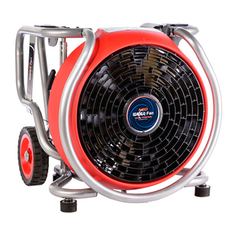
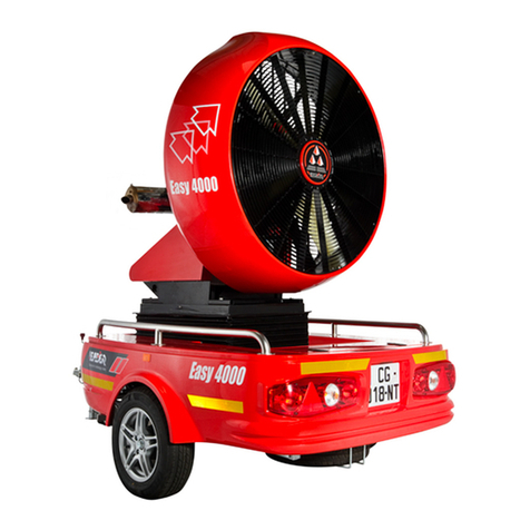
Leader EASY 2000 User manual

EASY 2000


Product number:
I60.30.120
EASY 2000 ON TRAILER + 1200 MM LIFT
I60.30.123
EASY 2000 ON TRAILER + 600 MM LIFT
I60.30.124
EASY 2000 ON TRAILER WITHOUT LIFT
I60.30.126
EASY 2000 ON SKID + 1200 MM LIFT
I60.30.125
EASY 2000 ON SKID + 600 MM LIFT
I60.30.121
EASY 2000 ON SKID WITHOUT LIFT

4
1INTRODUCTION 5
2SAFETY INSTRUCTIONS 5
3VERSION AND OPTION 7
4GENERAL CHARACTERISTICS & PERFORMANCE 8
4.1 General characteristics 8
4.2 Manufacturer’s plate 9
5DESCRIPTION 10
5.1 Engine instrument panel 10
5.2 Fuel valve 10
5.3 Circuit breaker and charger socket 10
5.4 Remote console 11
6COMMISSIONING INSTRUCTIONS 12
6.1 Fan stabilization for the trailer version 12
6.2 Starting the engine 12
6.3 Stopping the fan 14
6.4 Gasoline failure 15
6.5 Recharging the battery 15
6.6 Misting 15
6.7 Suction duct (Option) 16
6.8 Supply duct (Option) 16
6.9 Trailer (Option) 16
7MAINTENANCE OPERATIONS 17
7.1 Replacing the battery 18
7.2 Fuses 18
7.3 Information on engine oil level and changing 19
7.4 Lift table maintenance (option) 20
7.5 Front grid disassembly 21
7.6 Checking the propeller 21
7.7 Replacing the propeller 21
7.8 Fuel filter 22
7.9 Air Filter 22
7.10 Replacing the spark plugs 22
7.11 Changing the engine coupling bearing 22
8TROUBLESHOOTING 23
9SPARE PARTS 24
10 MAINTENANCE SERVICE BOOKLET 25
11 ANNEX 28
12 WARRANTY 30

5
1 INTRODUCTION
This manual was made in order to enable safe use of the EASY 2000 fans.
The instructions for use and maintenance must be followed in order to prevent any incident.
In order to improve this booklet, LEADER will be happy to read your suggestions.
Please don’t hesitate to contact us.
2 SAFETY INSTRUCTIONS
ATTENTION!
•This equipment has been constructed in accordance with EC directives. Its use is reserved to
firefighting professionals.
•Please read this manual completely as well as the instructions for use before commissioning and
using the equipment.
•Keep fingers and hands away from the turbine and moving parts.
•Only qualified and trained personnel should operate or repair this fan.
•Do not start the engine if the blades or casing show signs of alterations.
•Never move the fan when it is running.
•Never move the tilt or the lift when the fan is running at full speed.
•Always replace a defective part by an original part provided by LEADER.
•No disassembly must be performed before the battery is disconnected, the emergency stop
pressed and the ignition turned off.
•After a maintenance operation, make sure that all the tools used have been recovered.
•The EASY 2000 must not be used in explosive atmospheres.
•Do not stay in the fan outlet area (risk of projections).
•Keep the appliance away from children.
•Wear protective goggles, gloves and a noise-cancelling headset when using the fan.
•Do not wear clothes that are too loose which could be caught by the fan.
•Never allow a person to use a fan without having provided them with the necessary
instructions.
•Start the fan after making sure that it is in a stable position and that the trailer brake has been
applied.
•Do not drive with the lift deployed.
•Do not wash the fan with a high pressure cleaner.
•Do not touch the exhaust, risk of burns.
•Read the engine manual before using or performing maintenance on the EASY2000

6
ATTENTION –ATTENTION –ATTENTION
Area of occasional presence
R=15m
m
Wear protective equipment

7
SKID ROTATION VERSION
with lift
SKID VERSION
with lift
Lift table
(option)
TRAILER VERSION
with lift
Trailer
(Option)
TRAILER VERSION
without lift
Storage box
Gasoline
Jerrican 20L
(Option)
SKID ROTATION VERSION
without lift
360°
rotation
(option)
SKID VERSION
Tilt +20°/-
10°
Fuel tank
Circuit
breaker
Remote
console
Engine
control
Charger socket
battery
Misting
supply
SKID chassis
3 VERSION AND OPTION

8
4 GENERAL CHARACTERISTICS & PERFORMANCE
4.1 General characteristics
❖Manufacturer: LEADER SAS
ZI des hautes vallées
Chemin N°34
76930 OCTEVILLE SUR MER
France
❖Fan characteristics:
❖Engine characteristics:
Engine
HONDA GX630
Engine power
20.8Cv
Type
V- twin, 4 time
Cooling
Air
Cubic capacity
688 cm3
Rotation speed (Rpm)
2850 Tr/min
Start
Electric
❖Consumables:
Description
Type
Qty
Fuel
Unleaded gasoline 95 EN228
18L
Fuel additive
Fuel stabilizer
10ml/L
Engine oil
5W-30 Synthetic API SJ or later (CASTROL MAGNATEC)
1.9L
Model
EASY 2000 on trailer
EASY 2000 Skid
Lifting system
Without
600mm
1200mm
Without
600mm
1200mm
References
I60.30.124
I60.30.123
I60.30.120
I60.30.121
I60.30.125
I60.30.126
Free air delivery
150000m³/h
Propeller diameter
885mm
Height - mm
1715
1915
2050
1250
1510
1645
Width - mm
1430
1430
1430
1060
1060
1060
Length - mm
2800
2800
2800
1205
1205
1205
Weight - kg dry weight
301
402
447
158
275
320
Weight - kg in running order
324
425
470
178
295
340
Support
1-axle trailer with brakes, hitch ball and
sealed compartment.
Skid on steel chassis painted red epoxy
adaptable on trailer, pick-up truck platform,...
(All delivered on a pallet).
Misting system
For water or water with additive - 260 l/min at 7 bar
Autonomy
3 hours
Fuel tank
18 Litres
Fuel
Unleaded gasoline 95
Oil
Engine oil: 5W-30 Synthetic API SJ or later (CASTROL MAGNATEC) Hydraulic
oil for lift option: CASTROL SAF XJ 75-140
Battery
12V battery / 44 Ah for the electrical equipment power supply
Sound Level
93.9 dB at 7 m
Engine control panel
Attached to the engine (starter/start and electric stop/Hour meter/oil level light
Remote console
8m of cable (thimble inclination -10° to +20°/lift option/engine Stop/activation LED spotlight)

9
❖Available options:
360° Manual rotation system
For version on Skid only.
I60.30.129
Exhaust extension piece
Lg 2.5 m / Ø 50 mm (Advice: Use 3 extension cords end-to-end for more
effectiveness)
I60.30.003
Exhaust extension adapter
For connecting the exhaust extension
I60.30.128
Headlight
LED
I60.30.130
Truck
Truck in aluminium with handle and brake system for easy movement of
the EASY 2000 skid (without lifting system). W 1.2 x D 0.8 x H 1.1 m.
I60.30.119
Supply Duct
5 m spiral Ø 900 mm
I60.30.122
Suction duct
6 m spiral Ø 575 mm
I60.30.019
Gas tank for trailer
20L jerrican on steel bracket
I60.30.131
Pintle Eye (height-adjustable draw bar)
Allows the trailer to be coupled with a ring system (+70kg requiring a car
registration document according to the country of registration)
I60.30.132
Important information:
The fuel disintegrates when it is stored for more than 30 days. Degraded fuel causes acid
deposition and rubber residues in the fuel circuit or on essential parts of the carburettor. To keep
the fuel in good condition, use a fuel stabilizer. Use Ethanol Free gasoline where possible.
When you add a fuel stabilizer, fill the fuel tank with fresh gasoline. If the tank is only partially filled,
the air inside promotes fuel degradation during storage. When storing a refueling jerrycan, make
sure that it only contains fresh fuel.
Unleaded gasoline
The United States
Pump octane rating of at least 86
Except The United States
Research octane number of at least 91
Pump octane rating of at least 86
Procedure for adding fuel stabilizer to prolong the storage duration:
1. Add the stabilizer by following the manufacturer’s instructions 10ml per litre of fuel.
2. After having added the fuel stabilizer, let the engine run outside for 10 minutes to be sure that
the treated fuel has replaced the existing fuel in the carburettor.
3. Stop the engine and if the tank is equipped with a fuel cock, place it on the closed position.
4.2 Manufacturer’s plate
This information will be needed for ordering parts and requests for technical information or concerning
the guarantee.
Engine serial number: ……………………………………………..
Manufacturing company plate

10
Oil warning light:
The Oil Alert system protects the motor against damage
due to the lack of oil in the engine crankcase. Before the
engine crankcase oil level drops below a security threshold,
the Oil Alert warning light (red) will light up and the Oil
Alert system automatically stops the engine (the engine
power switch remains in the ON position).
If the engine stops and will not restart, check:
1. The engine oil level See § 7.3
2. That the engine is not in a sloped use configuration
of more than 20°.
Hour meter:
It counts the elapsed time of use of the engine after start
up.
5 DESCRIPTION
5.1 Engine instrument panel
5.2 Fuel valve
5.3 Circuit breaker and charger socket
Fuel
level
Fuel valve
The fuel valve is located
under the tank.
Circuit breaker:
Allows you to switch off the
electrical supply.
Throttle Lever
STARTER
Key switch to stop
the engine
Oil warning
light
Hour
meter
Charger socket:
Allows you to charge the battery.

11
Never connect or disconnect the remote control when
the engine is running.
5.4 Remote console
The remote console allows you to control the EASY 2000 from a distance. It is equipped with an 8m cable.
This console allows you to control the following functions: Tilt adjustment, lift adjustment (optional), area
lighting (optional) and "STOP” punch switch which allows you to switch off the engine.
1-LED light switch: It activates the LED light located on the ferrule. (LED headlight optional).
2-Tilt Joystick: Allows for tilting from -10° to +20°.
3-LED indicator light: When the green LED indicator light is illuminated, it indicates that the
LED headlight is in operation. (The LED light is available as an optional).
However, the green LED indicator light is functional and will light up if
the joystick is ON, (even if the light is not fitted).
4-Lift Joystick: Allows for the raising and lowering of the fan lift table (optional).
(If the lift option is absent, a plug will replace the control joystick).
5-General shut down: Punch switch for stopping the engine, lifting and tilting from the console
6-Ready to Start indicator light: II indicates that the fan is ready to be used:
1) Circuit breaker "On"
2) The emergency stop is not engaged
3) Oil level is okay
4) Trailer brake applied (optional)
The remote console is equipped with a connector that allows for quick maintenance. You don’t have
to disconnect this socket between 2 uses.
4
2
3
5
6
1

12
6 COMMISSIONING INSTRUCTIONS
6.1 Fan stabilization for the trailer version
On the trailer version, the central rear strut is for stabilising the trailer on sloped or uneven ground.
Its installation is essential to avoid the device tipping over when using the lift.
Check that the engine is not tilted more than 20° in order not trigger the low oil
security mechanism (Oil alert).
1: Make sure that the handbrake is firmly applied on the trailer versions
2: Pull the red handle, the strut will rotate toward the ground.
3: Stabilize the fan by adjusting the strut by using the crank provided in the box.
6.2 Starting the engine
•Check the fuel levels and engine oil before commissioning.
•Circuit breaker "ON".
•Check that the STOP button on the remote control is not pressed.
(Rotate the button to unlock).
•Adjust the desired tilt and lift by using the joysticks.
•Check that the "Ready to Start" indicator light of the remote control is green.
•Check that the valve under the fuel tank is in the OPEN position before starting the engine.
1
2
3

13
➢To start a cold engine, pull the choke pull knob on the
CLOSED position.
➢To start a warm engine, push the choke knob in.
➢Move the throttle lever from the MIN position.
To approximately 1/3 from the MAX position.
➢Place the key in the engine switch.
(A set of 2 keys is provided with the fan).
➢Turn the engine start key to the ON position.
➢Continue to turn the key in a clockwise direction to
the start position to activate the starter motor.
Place the key to the START position and hold it in this
position until the engine starts.
At the first start-up or following a fuel failure, it is normal that the engine does not start
after 5 seconds; this is due to priming the fuel pump.
In other cases, if the engine does not start within 5 seconds, release the key and wait at
least 10 seconds before activating the starter again.
When the engine starts, release the key; it should return to the ON position.
After start-up:
➢Warm up the engine at low speed for 2 or 3 minutes.
➢If the starter is on the CLOSED position, push it progressively to the OPEN position as the engine
heats up.
➢Gradually increase the speed using the throttle lever.
Starter
Starter
Throttle
lever
Engine switch key
ON
START
0

14
The exhaust system will remain very hot after use.
6.3 Stopping the fan
In an emergency situation to stop the EASY 2000, push the emergency stop
of the Remote console.
To stop the fan according to the standard procedure:
➢Decrease the engine speed to the minimum by placing the gas control lever on the MIN position.
➢Using the key, place the engine switch on the OFF position, the engine must stop.
➢Close the valve of the fuel tank.
➢Bring the tilt to 0°.
➢Bring the lift to 0°.
➢Put the circuit breaker on OFF.
➢Allow the engine to cool down for a few minutes.
➢Store the accessories if you have the trailer option (exhaust sheath, wheel chocks, strut...).
Emergency stop
Throttle
lever
Engine switch key

15
6.4 Gasoline failure
After a gasoline failure, you must re-prime the fuel pump by using the following procedure:
Activate the starter. If the engine does not start within 5 seconds, release the key and wait at least
10 seconds before activating the starter again. This is due to priming the fuel pump.
When the engine starts, release the key; it should return to the ON position.
6.5 Recharging the battery
The EASY2000 is fitted with a socket for recharging the battery.
In order to ensure a sufficient charge level, it is recommended to recharge the battery once a month.
A charger is provided with the fan. The charger can be maintained connected without any time limit
6.6 Misting
The misting system must be supplied with water after the engine is started. On the versions with lift,
the fan will need to be raised before the water is supplied. The connection is delivered in male thread
1"1/2BSP.
Misting water connection
Battery charger socket
Battery charger

16
6.7 Suction duct (Option)
It is imperative to install it before installing the start-up.
3 mounting hooks are provided on the rear grid for
mounting the suction duct as well as a protection in
order to avoid contact with the exhaust manifold.
6.8 Supply duct (Option)
It is imperative to install it before installing the start-up.
Straps with hooks are provided on the supply duct
for mounting it near the rear grid.
6.9 Trailer (Option)
When towing the EASY2000, the following precautions must be taken:
•The stabilization strut must be raised.
•The hand brake released.
•The jockey wheel must be raised or disassembled and stored in the box.
•The pintle hook connection verified.
•The safety cable secured to the vehicle tractor.
•The electrical connector in place on the vehicle tractor.
•The signal lights checked.
Stabilisation
strut
Hand brake
Signal lights
Jockey
wheel
Safety cable
Electrical Connector
Exhaust manifold
protection (series)
3 hooks
(series)
6M Suction
duct
5M
Supply
duct

17
7 MAINTENANCE OPERATIONS
Maintenance programme
Maintenance level:
Level 1: Can be performed by users.
Level 2: done only by a Qualified mechanic.
Operations
Before every start-
up
After every use
First 20 hours
Or first month
Every 100 hours or
every 6 months
Every 200 hours or
every 2 years
Chapter
Maintenance level
Check fuel level
X
Cf.4.2
1
Check engine oil level
(Add oil if necessary)
X
Cf.7.3
1
•Complete fuel level
•Propeller condition (visual inspection
without disassembly)
On trailer version:
•Make sure the crank is present
•Check the condition of the strut
•Check signalling (Lighting, brake lights…)
•Tire pressure
X
1
Change the engine oil
X
X
Cf.7.3
2
Replace the oil filter
X
Cf.7.3
2
Cleaning air filter
X(1)
Cf. engine
leaflet
2
Replace air filter
X
Cf.7.8
1
Clean and check the spark arrester
X
Cf.
engine
leaflet
1
Lift table maintenance
X
Cf.7.4
2
Check propeller
X
Cf.7.6
1
Replace fuel filter
X
Cf.7.7
2
Replace the spark plugs
X
Cf. engine
leaflet
2
Replace the bearing of the engine coupling
X
Cf.7.10
2
(1) In the case of use in dusty environments, increase the frequency of maintenance.

18
7.1 Replacing the battery
7.2 Fuses
Main protection:
Cartridge fuse 10A (5mm x 20mm)
Located on the electronic unit next to the remote console connection.
Battery charger protection:
Cartridge fuse 10A (5mm x 20mm)
Located on the electronic unit next to the remote console connection.
No disassembly must be performed before the emergency stop
pressed and the ignition turned off.
All interventions must be performed on a cold engine.
Before any intervention on the lift table, install the security
mechanism as described in paragraph cf.6.4.
- Remove the battery cover by unscrewing the 4 screws.
- Remove the positive terminal of the battery.
- Remove the negative terminal of the battery.
- Remove the old battery.
- Install the new battery.
- Connect the negative terminal first.
- Connect the positive terminal.
- Fasten the battery cover by tightening the 4 screws.
Battery cover
Battery
Battery charger fuse
Main fuse

19
7.3 Information on engine oil level and changing
➢Frequency of oil level checks: Before every start-up.
Engine oil level:
Using the engine with a low oil level can deteriorate engine and is not covered by
the warranty
➢Frequency of oil changes: Every 100 hours or every 6 months.
➢Frequency of oil filter replacements: Every 200 hours or every 2 years.
- The engine oil level is visible on the gauge.
- The oil level should be between the lower and
upper limits. It must be checked on a cold engine
at least 5 minutes after stopping it. The warmer
the engine, the higher the level will be.
- Add oil if necessary.
Never open the engine oil tank cap when the engine is hot. Wait at least 25 min
after stopping the engine.
- Place a suitable container under the engine to
collect the used oil.
- Remove the oil filler cap, the drain cap screw and
the sealing washer.
- Completely drain the used oil.
- Install the drain plug with a new sealing washer
and tighten it completely.
- Fill the oil tank with new oil (5W30).
- Retighten the filler plug.
- Remove the oil filter and drain the oil into a
suitable container.
- Discard the oil and the old filter in a manner
that is compatible with the environment.
- Preferably use a tool to remove the oil filter.
- Put the new oil filter in place by tightening it
with your hand until it blocks.

20
Position the safety bar in the holes of the lower rails of the table
7.4 Lift table maintenance (option)
➢Frequency: Every 100 hours or every 6 months.
•Put the table in the upper stop.
•Lift the bellow and hold it in place by using the straps (not included).
•Positioning the safety bar (supplied with the device)
•Lubricate the lower and upper rails to the right and to the left with graphite grease.
•Check the oil level in the pump reservoir. It must contain at least 2cm of oil when the table is at the
upper stop, complete with hydraulic oil if necessary.
2cm minimum
Upper rail to be greased
Lower rail
Filler plug
Adjusting the lowering speed:
Loosen to increase the speed
Adjusting the pressure:
Loosen to increase pressure (150bar max)
Lower rail to be greased
Safety bar
Pump tank
Bellow
Straps
This manual suits for next models
6
Table of contents
Other Leader Fan manuals