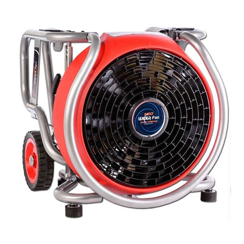
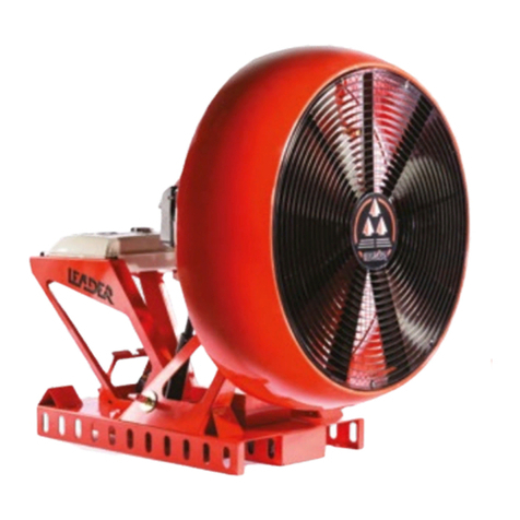
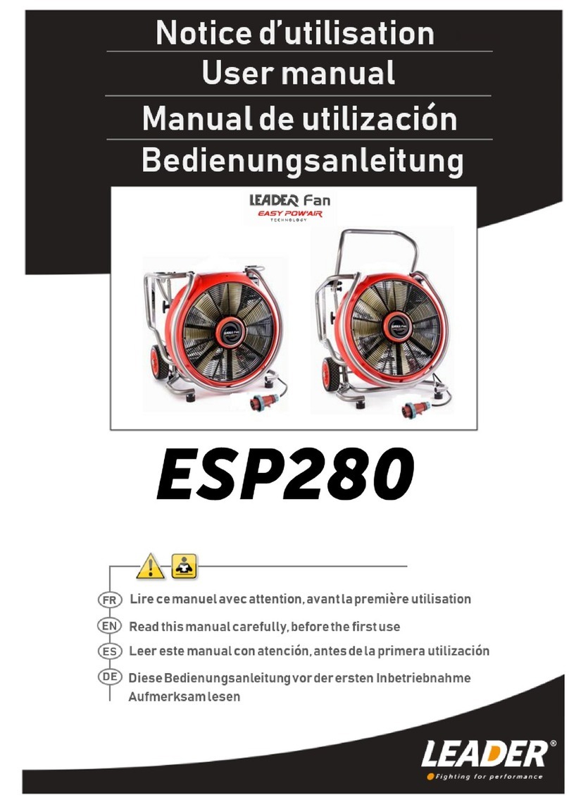
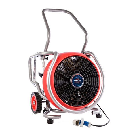
Leader EASY 4000 User manual


Product reference :
Reference
Product
I60.30.109
EASY 4000 SUR REMORQUE + ELEV 1200 MM + ATTELAGE BOULE
I60.30.114
EASY 4000 SUR REMORQUE + ELEV 600 MM + ATTELAGE BOULE
I60.30.113
EASY 4000 SUR REMORQUE SANS ELEVATION + ATTELAGE BOULE
I60.30.112
EASY 4000 SUR SKID + ELEVATION 1200
I60.30.111
EASY 4000 SUR SKID + ELEVATION 600
I60.30.110
EASY 4000 SUR SKID + SANS ELEVATION
I60.30.117
EASY 4000 SUR SKID + ELEVATION 1200 + ROTATION
I60.30.115
EASY 4000 SUR SKID + ELEVATION 600 + ROTATION

2
1INTRODUCTION 4
2SAFETY ADVICE 4
3GENERAL SPECIFICATIONS & PERFORMANCES 5
General features 5
Engine specification 8
Capacities 8
Options 8
Manufacturers serial plate 8
4COMMISSIONING INSTRUCTIONS 9
Dashboard 9
Starting up 10
Stopping 10
Remote control 11
Run out of petrol 11
Atomisation 12
Wheel block 12
Suction duct 12
Duct blow 12
Rear stabiliser stand 12
Battery recharge 13
Towing 13

3
5MAINTENANCE OPERATIONS 14
Maintenance programme 14
Removing the casing and the bellows 15
Fuses 16
Levels 17
Adjusting the engine speed 18
CLEANING THE RADIATOR 18
Elevation (Option) 18
Air filter 20
Air filter clogging indicator (optional) 20
Changing the gearbox oil 21
Changing the motor oil 22
Spark plugs 23
Fan 24
Fuel filter 24
Exhaust spring 25
Alternator belt 25
6FAILURE 26
7SPARE PARTS 27
8MAINTENANCE LOG BOOK 29
9ANNEXE 30
10WARRANTY 34

4
1INTRODUCTION
This booklet has been produced to help you use and install the EASY 4000 ventilators safely.
The instructions for use and maintenance must be followed to prevent any incidents.
To make improvements to this booklet, LEADER, welcomes your suggestions. Do not hesitate to let us know.
2SAFETY ADVICE
•This equipment is manufactured in compliance with EC directives. Its use is reserved for firefighting
professionals only.
•Read the whole of this manual and the instructions for use before commissioning and using the
equipment.
•Keep fingers and hands away from the turbine and the moving parts.
•Only have this ventilator operated and repaired by qualified, trained personnel.
•Do not start the motor if the blades or the casing show signs of alterations.
•Never move the ventilator while it is operating.
•Never change the angle or the elevation or the rotation when the ventilator is at full speed.
•Always replace a defective part by an original part supplied by LEADER.
•Do not dismantle before having disconnected the battery, pushed down the emergency stop and cut the
contact.
•After a maintenance operation, check that all tools that were used have been retrieved.
•Blower ventilators must not be used in explosive atmospheres.
•Do not stand in the ventilator discharge zone (risk of projections).
•Keep out of the reach of children.
•Wear protective goggles, gloves and a soundproof helmet when using the ventilator.
•Do not wear too loose clothes that could become entangled in the ventilator.
•Never authorise anyone to use a ventilator without having supplied the necessary instructions.
•Start the ventilator after having made sure it is in a stable position, that the wheel blocks are installed
and that the trailer brake is on.
•Do not drive with the elevation deployed.
•When used in extraction the EASY4000 must be positioned away from the fireplace and must not be
exposed to temperatures above 60 ° C (140°F).
•The air filters must not be clogged (see §5.8).
•Use only the accessories provided and validate by LEADER.

5
3GENERAL SPECIFICATIONS & PERFORMANCES
General features
❖Manufacturer: LEADER
ZI des hautes vallées
Chemin N°34
76930 OCTEVILLE SUR MER
FRANCE
▪Working area LED illuminated.
▪blade fan.
▪Water Mist/Atomisation 260 l/min (68.7Gpm) at 7 bar (100Psi) from 5 nozzles. Maximum pressure 10 bar (145Psi).
▪Fan driven by a rack gear reducer and a centrifuge gear.
▪Battery recharge socket.
▪Wheel block.
▪Sound level at 7m: 96dBA
▪Fuel: Lead-free octane 95 petrol
▪Rated air flow: 180,000m3/h (6356640 cu ft/h)
▪Running time: 1h40
R=49.2ft

6
Size:
TRAILER VERSION
Version
Option
Height
A
Width
B
Length
C
working Weight
Trailer
(tow-bar)
without elevation
2185 mm
(7,17ft)
1690 mm
(5,55ft)
3300 mm
(10,80ft)
579kg (1276,5ib)
elevated
to+600mm
(1,97ft)
2215 mm
(7,27ft)
1690 mm
(5,55ft)
3300 mm
(10,80ft)
680kg (1499ib)
With Elevated
+1200mm
(3,94 ft)
2315 mm
(7,60ft)
1690 mm
(5,55ft)
3300 mm
(10,80ft)
725kg (1598ib)
Angle
+20°/-10°
Elevator table (optional)
Misting/Atomisation/Water inlet
Stowage area
Fuel tank
Control panel

7
SKID VERSION
Version
Option
Height
A
Width
B
Length
C
working Weight
Skid
Without elevation
1618 mm
(5,31ft)
1482 mm
(4,82ft)
1815 mm
(5,96ft)
405kg (893ib)
With elevation +600mm
(1,97ft)
1789 mm
(5,87ft)
1482 mm
(4,82ft)
1815 mm
(5,96ft)
506kg (1115,6ib)
With elevation +1200mm
(3,94 ft)
1922 mm
(6,30ft)
1482 mm
(4,82ft)
1815 mm
(5,96ft)
551kg (1214,8ib)
Skid with 360°
rotation
Without elevation
1792 mm
(5,87ft)
1482 mm
(4,82ft)
1815 mm
(5,96ft)
474kg (1045ib)
With elevation +600mm
(1,97ft)
1963 mm
(6,44ft)
1482 mm
(4,82ft)
1815 mm
(5,96ft)
575kg (1267,7ib)
With elevation +1200mm
(3,94 ft)
2096 mm
(6,88ft)
1482 mm
(4,82ft)
1815 mm
(5,96ft)
620kg (1366,9ib)
Battery charger socket
Rotation 360°(Option)
Elevator table (optional)
Misting/Atomisation/Water inlet
Fuel tank
Control panel
Angle
+20°/-10°

8
Engine specification
▪Brand: BMW.
▪Type: Flat two-cylinder, 4 strokes.
▪Displacement: 1170cm3.
▪Power: 115HP.
▪Alternator: 5000W.
▪Speed: Up to 7000rpm.
▪Cooling: Air and oil cooled.
▪Start-up: Electronic ignition.
▪Exhaust: Catalytic converter.
▪Injection and double ignition: Electronic
Capacities
Description
Type
Qty
Fuel
Lead-free octane 95 EN228
42L (11.10Gal)
Motor oil
CASTROL Power1 Racing 10W40
API SL - JASO MA2
4L (1,057Gal)
Gearbox oil
CASTROL SAF XJ 75-140
YACCO BVX C100 85W140
0.25L(0.066Gal)
Options
•Elevation +600mm (1,97ft).
•Elevation +1200mm (3,94 ft).
•Rotation 360° (on SKID version).
•Projector.
•Exhaust evacuation duct: avoids sending exhaust fumes into a ventilated room. 4 ducts each with a unit
length of 2.5m (13.12ft)can be combined.
•Remote control.
•Suction duct.
•Duct blow.
•Air filter clogging indicator.
Manufacturers serial plate
Serial number
Manufacturer
Designation
Date of manufacture
Reference

9
4COMMISSIONING INSTRUCTIONS
Dashboard
1- Battery cut-off: Provides electric power to the entire ventilator.
2-Ignition: Used to start and stop the motor.
3-Starter: Used to start the engine.
4-Emergency stop: Used to stop the engine, the elevator table and the angle.
5-Rev counter: Used to control engine output.
6-Hour meter: Used to view engine operating time. It is triggered as soon as the ignition
is “ON”.
7-Fuel level: Shows 25min of running time per ¼ fuel tank at full power.
8-Engine temperature: Indicates the motor oil temperature. It must remain below 130°C (266°F).
9-Engine power: Used to regulate the ventilator speed.
10-Oil pressure: Indicates the motor oil pressure.
11-Elevation: Used to raise and lower the ventilator (optional).
12-Angle: Used to change the angle from -10° to +20°.
13-Voltage indicator: Indicates when power is on. It switches from green to red when
the battery is low.
14-Fuel alarm: Switches from green to red when low on fuel.
15-Brake indicator: Switches from red to green when the trailer brake is on. The engine
cannot be started unless the brake is on.
16-oil pressure: Switches from red to green if oil pressure is correct after the engine is
started. It remains red when the engine is stopped.
17-Fuel primer: This valve is allow the priming the fuel pump after a run out of fuel.
17
5
12
14
15
9
13
11
2
3
7
8
6
10
16
4
1

10
Do not leave the engine idling for more than 5 minutes
Avoid using a continuous speed between 3500 and 4500 rpm to protect unit
from vibration.
The exhaust system remains very hot after use
Starting up
Before starting up, make sure the trailer is in a stable position that its brake is on and the wheel blocks are in place.
On uneven ground, use stabiliser stands (see 4.6).
•Check the fuel and motor oil levels before starting up.
•Check that the emergency stop is not pushed down (it is unlocked by rotating it).
•Check that the fuel primer valve [17] is on “ON” position.
•Put the battery cut-off switch [1] on “1”: The control panel should illuminate.
•Adjust the required angle and elevation using the joysticks [11] and [12].
•Check that all indicators [13], [14] and [15] are green.
•Put the accelerator [9] at... minimum.
•Turn the ignition [2] to “ON” after having lifted the cover.
•Press the starter [3] for a maximum of 5 seconds.
•Once the engine has started, make sure the oil pressure indicator is green and that the pressure on the dial
[10] is sufficient (approx. 6 bar (87Psi)).
•In order to protect the engine, only increase engine power once the temperature [8] has reached 50°C (122°F).
The engine speed must be between 1300 rpm (±100) when idling on a cold engine and 6900 rpm (±100) at full power.
Stopping
•Reduce the engine speed to the minimum [9].
•Turn the ignition [2] to “OFF”.The engine should stop.
•Adjust the angle [11] and elevation [12] to “0”.
•Put the battery cut-off switch [1] on “0”.
•Let the engine cool for a few minutes.
•Stow the accessories (exhaust duct, wheel blocks, etc.).

11
Connecting the remote control deactivates the slope, elevation and engine power
controls on the main console.
Never connect or disconnect the remote control. when the motor is running.
Remote control
The remote-control option allows the EASY 4000 to be remotely controlled. It is fitted with a 13m cable. The use of
this accessory makes it possible to adjust the slope, the elevation and the engine speed. After having connected the
remote control, these 3 functions are no longer active on the main console. The "STOP" command on the remote
control makes it possible to turn off the motor.
1-Slope: Used to change the angle from -10° to +20°.
2-Elevation: Used to raise and lower the ventilator (option).
3-Engine power: Used to regulate the ventilator speed.
4-Stopping the motor: Used to stop the engine using the remote control. Unlike the console emergency stop, it
will not stop the slope or elevation controls.
Setting up
•Connect the remote control to the connector near the console
•Check that the "STOP" button has not been pushed
•Set the engine power to the minimum on the remote control and the console
•Resume the start-up procedure (see.4.2)
Run out of petrol
After a run out of fuel, you must priming the fuel pump following the procedure:
•Check the fuel and motor oil levels before starting up.
•Check that the emergency stop is not pushed down (it is unlocked by rotating it).
•Put the battery cut-off switch [1] on “1”: The control panel should illuminate.
•Put the priming valve [17] on “FUEL PRIMER”.
•Turn the ignition [2] to “ON” after having lifted the cover and turn off it after 4 seconds.
•Begin again 3 times.
•Put the priming valve [17] on “ON”.
•Turn the ignition [2] to “ON” after having lifted the cover and turn off it after 4 seconds.
•Begin again 3 times.
•Doing the starting up procedure (see.4.2).
Remote control socket
1
4
2
3

12
Atomisation
Misting/Atomisation must only be connected after the engine has
started. On versions with elevation, the ventilator must be raised
before the water supply is turned on.
The connection is supplied with a male 1"1/2BSP threading.
Wheel block
On the trailer version, 4 wheel blocks are shipped with your
ventilator. It is imperative to install them before starting up.
They guarantee that the ventilator is immobilised if the hand
brake fails.
Suction duct
It is imperative to install it before starting.
3 fixing hooks are provided on the rear grid for attachment of the
suction duct.
Duct blow
It is imperative to install it before starting.
Straps with hooks are provided on the discharge duct for
attachment to the ends of the rear gate.
Rear stabiliser stand
On the trailer version rear stands are provided to stabilise
the trailer on sloping ground. They must be installed to avoid the
appliance tipping over when elevation is used.
Block
Hooks
Suction duct
Duct blow
Stands x2

13
Battery recharge
The EASY4000 has a standard battery recharge socket located in the rear trunk.
A charger is delivered.
Towing
When towing your EASY4000 the following precautions are to be taken:
•The Jockey wheel must be dismantled.
•The connection to the towing hook must be checked.
•The safety cable must be attached to the towing vehicle.
•The electric connector must be installed on the towing vehicle.
•The indicator lights must be checked.
•The shroud protection put in place.
SKID Version
Trailer Version
Battery recharge socket
Battery recharge fuse
In order to guarantee a sufficient
charge level, it is recommended to
charge the battery once every
month or when the indicator
switches to red.
Safety cable
Electrical connector
Jockey wheel
Trailer hook
Indicator lights
Shroud protection

14
5MAINTENANCE OPERATIONS
Maintenance programme
Maintenance level:
Level 1: Can be carried out by users.
Level 2: only carried out by a qualified mechanic.
Level 3: only carried out by the manufacturer.
Inspection or works
Maintenance frequency
Maintenance level
After each start-up
After each use
10 first hours
of operation
Every 2 years
Every 50 hours
Every 100 hours
Every 200 hours
Chapter
Check the fuel level
Check the motor oil level
X
5-4
1
•Top up the fuel level
•Fan condition (visual
inspection without removal)
On the trailer version:
•Check for the presence of the
Wheel Block, the Jack
•Check the condition of the
stand
•Check the indicator lights
(Lights, brake lights, etc.)
•Tire pressure
•Presence of the spare tire
X
1
Change the gearbox oil
X
X
5.9
2
Change the motor oil + Filter
X
X
X
5.10
2
Clean the radiator
X
5.6
2
Elevation servicing
X
5.7
2
Adjust the motor speed
X
5.5
2
Inspect the exhaust pipe spring
X
5.14
1
Replace the exhaust pipe spring
X
5.14
2
Inspect the fan
X
5.12
1
Replace the fuel filter
X
5.13
2
Replace the air filter
X
5.8
1
Check the alternator belt
X
5.15
2
Replace the spark plugs
X
5.11
2
Change the alternator belt
X
5.15
2
Check the screwing mark
X
1

15
Nothing must be dismantled unless the emergency stop has been pushed down and the ignition cut.
All interventions should be on a cold engine.
Before working on the elevating table, install the safety as described in paragraph (see.5-6).
Removing the casing and the bellows
Casing under the engine:
•Remove the 6 M5 Allen head screws.
•Remove the 2 M8 nuts.
Front grate:
•Loosen the nuts.
•Unlock the grate by pivoting it clockwise.
•Remove the grate.
3 M5 Allen head
screws per side
Pivoting in the
clockwise direction
Nut to loosen

16
Elevator table bellows (option):
•Put the ventilator in the high position.
•Lift the bellows manually to access under the elevator table (there are no fixtures on the base of the bellows).
Fuses
10A FUSE: CONTROL PANEL PROTECTION
Located under the control panel.
10A FUSE: ECU PROTECTION (Electronic control unit)
Located under the control panel.
10A FUSE: BATTERY CHARGER PROTECTION
Located next to the charger socket.
20A FUSE: ENGINE EQUIPMENT PROTECTION
Located behind the oil radiators, close to the battery.
Bellows
SKID
version
Trailer
version
Fuse

17
Levels
Frequency: Before each start-up.
Motor oil level:
The motor oil level is visible in the
porthole located to the rear right of the
engine.
The oil level must be between the
bottom and top of the red circle. It must
be checked on a cold engine at least
5 minutes after it has been stopped. The
hotter the engine, the higher the level
will be.
Oil top-up is done via the top of the
right cylinder. Top-ups should be made
on a cold engine. Use the BMW wrench
(ref: 2005749) to open the tank cap.
Filling the fuel tank:
The fuel level is checked on the control panel screen.
Never remove the motor oil tank cap when the motor is hot. Wait for at least 25
minutes after stopping the engine.
Motor oil level
Motor oil cap
Recommended type of fuel:
- min. RON90
- EN228 Regular
- EN228 Premium
- EN228 Premium plus
Fuel tank access
cap

18
The potentiometer adjustments must be made on a stopped engine.
INSTALL THE SAFETY DEVICE SHIPPED WITH THE TABLE IN THE HOLES IN
THE LOWER RAILS WHEN IT IS RAISED.
Adjusting the engine speed
Frequency: Every 50 hours.
An electric cylinder controls the engine speed.
Engine speed is adjusted using its control which is located on the control panel.
Idling speed on a hot engine at 2000rpm:
•Check the engine idling speed.
•After having stopped the engine, adjusted.
the idling adjustment potentiometer.
•Restart the engine to check the adjustment.
Maximum speed to be adjusted on a hot engine at 6800rpm:
•Check that the engine speed is on full power.
•After having stopped the engine, adjusted the max speed adjustment
potentiometer.
•Restart the engine to check the adjustment.
NB: the engine's ECU (Electronic control unit) limits the speed to 7000rpm.
At this speed the engine can misfire. It is therefore imperative not to exceed it.
CLEANING THE RADIATOR
Frequency: Every 50 hours.
When using in a very smoky environment, the frequency of cleaning needs
to be increased.
2 oil radiators are located in the engine underside structure.
•Remove the casing under the engine (see.5.2).
•Clean the radiator using a compressed air nozzle.
Elevation (Option)
Frequency: Every 50 hours.
•Put the table in the high position.
•Remove the upper part of the bellows with the table (see.5.2).
Engine speed control
on the control panel
Adjusting idling
speed
Max speed
adjustment
Oil radiators
Drill holes

19
•Grease the lower and upper right and left rails.
•Check the oil level in the pump tank and top up if required using hydraulic oil.
Lower rail
Upper rail
Rails to be
greased
2cm minimum
in the upper
position
Adjustment of the lowering speed
Loosen to decrease the speed
Pressure adjustment
Loosen to decrease the pressure Max
150bars
Filling cap
In the event of malfunction of the pump if the table is in the up position, to make it go back down,
operate the emergency valve. Do not forget to put the valve back to its original position.
In the trunk
On the chassis
ON
SKID
version
Trailer
version
This manual suits for next models
8
Table of contents
Other Leader Fan manuals