Leader Hasty User manual


1

2
Product references
D11.04.349
LEADER Hasty - 2.4m probe & 1 wireless sensor
D11.04.351
LEADER Hasty - 2.4m probe & 2 wireless sensors
D11.04.359
LEADER Hasty - 2.4m probe & 3 wireless sensors
D11.04.350
LEADER Hasty - 4m probe & 1 wireless sensor
D11.04.352
LEADER Hasty - 4m probe & 2 wireless sensors
D11.04.360
LEADER Hasty - 4m probe & 3 wireless sensors

3
1INTRODUCTION---------------------------------------------------------------------------------------------------------------------------------------------------4
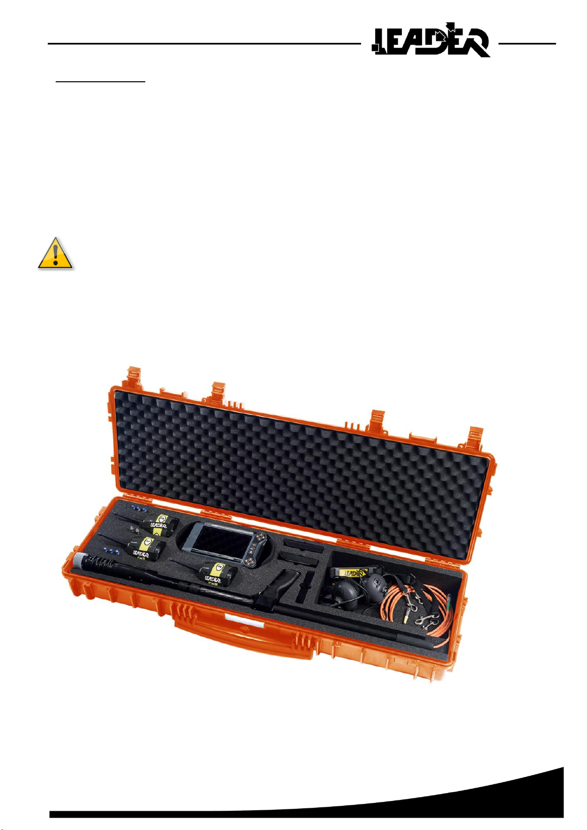
1.1 LEADER HASTY PRESENTATION---------------------------------------------------------------------------------------------------------------------------4
1.2 LEADER HASTY COMPOSITION ----------------------------------------------------------------------------------------------------------------------------4
1.3 GENERAL FUNCTIONS ----------------------------------------------------------------------------------------------------------------------------------------6
1.4 DETAILED TECHNICAL SPECIFICATIONS---------------------------------------------------------------------------------------------------------------------6
2LEADER HASTY DESCRIPTION -----------------------------------------------------------------------------------------------------------------------------7
2.1 CONTROL BOX DESCRIPTION --------------------------------------------------------------------------------------------------------------------------------7
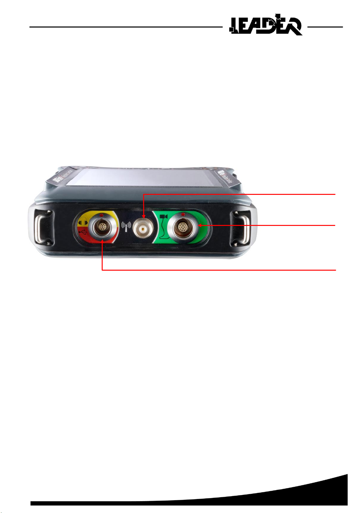
2.2 CONNECTION DESCRIPTION----------------------------------------------------------------------------------------------------------------------------------8
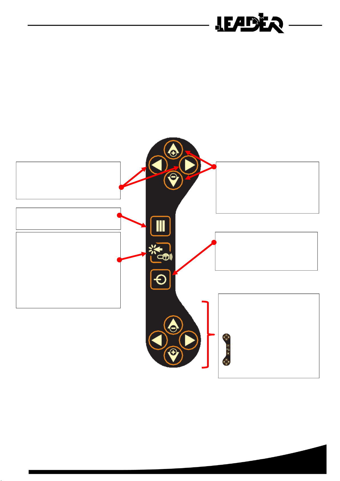
2.3 KEYBOARD DESCRIPTION ------------------------------------------------------------------------------------------------------------------------------------9
2.4 DESCRIPTION OF THE TELESCOPIC BOOM---------------------------------------------------------------------------------------------------------------- 10
2.5 AUDIO HEADSET DESCRIPTION ---------------------------------------------------------------------------------------------------------------------------- 12
2.6 DESCRIPTION OF THE WIRELESS SEISMIC SENSOR ----------------------------------------------------------------------------------------------------- 13
3USING THE CONTROL BOX -------------------------------------------------------------------------------------------------------------------------------- 14
3.1 CONTROL BOX POWER SUPPLY---------------------------------------------------------------------------------------------------------------------------- 14
3.2 POWERING ON THE CONTROL BOX------------------------------------------------------------------------------------------------------------------------ 15
3.3 USING THE SUN SHIELD------------------------------------------------------------------------------------------------------------------------------------- 16
4SEISMIC SEARCH MODE------------------------------------------------------------------------------------------------------------------------------------ 17
4.1 USING THE SEISMIC SENSOR ------------------------------------------------------------------------------------------------------------------------------ 17
4.2 PAIRING THE SEISMIC SENSOR ---------------------------------------------------------------------------------------------------------------------------- 18
4.3 SEISMIC SEARCH MODE ------------------------------------------------------------------------------------------------------------------------------------ 19
4.3.1 Seismic mode specificities-------------------------------------------------------------------------------------------------------------------------- 19
4.3.2 Selection of seismic mode settings--------------------------------------------------------------------------------------------------------------- 21
4.4 MENU:DESCRIPTION OF THE SEISMIC MODE FUNCTIONS---------------------------------------------------------------------------------------------- 22
4.4.1 Filter control function--------------------------------------------------------------------------------------------------------------------------------- 22
4.4.2 Sensor battery level function----------------------------------------------------------------------------------------------------------------------- 23
4.4.3 Function to set screen brightness----------------------------------------------------------------------------------------------------------------- 25
4.4.4 Left hander / right hander function---------------------------------------------------------------------------------------------------------------- 25
4.4.5 Switching to camera mode ------------------------------------------------------------------------------------------------------------------------- 25
5SEARCH CAMERA MODE ----------------------------------------------------------------------------------------------------------------------------------- 26
5.1 USING THE MAIN FUNCTIONS ------------------------------------------------------------------------------------------------------------------------------ 26
5.1.1 Camera direction function--------------------------------------------------------------------------------------------------------------------------- 26
5.1.2 Boom end lighting intensity function-------------------------------------------------------------------------------------------------------------- 27
5.1.3 Push to Talk function (Communicating with the victim) ------------------------------------------------------------------------------------- 27
5.2 MENU:DESCRIPTION OF THE SEARCH CAMERA MODE ICONS----------------------------------------------------------------------------------------- 28
5.2.1 Zoom function------------------------------------------------------------------------------------------------------------------------------------------ 29
5.2.2 Image rotation function ------------------------------------------------------------------------------------------------------------------------------ 30
5.2.3 Photo / video recording functions----------------------------------------------------------------------------------------------------------------- 31
5.2.4 Photo / video viewing function--------------------------------------------------------------------------------------------------------------------- 35
5.2.5 Right hand / left hand function--------------------------------------------------------------------------------------------------------------------- 37
5.2.6 Screen brightness function ------------------------------------------------------------------------------------------------------------------------- 37
5.2.7 Audio headset function ------------------------------------------------------------------------------------------------------------------------------ 38
5.2.8 Loud speaker function ------------------------------------------------------------------------------------------------------------------------------- 38
5.2.9 Switching from the Camera mode to the seismic mode------------------------------------------------------------------------------------- 39
6TROUBLESHOOTING ----------------------------------------------------------------------------------------------------------------------------------------- 39
7WARRANTY ------------------------------------------------------------------------------------------------------------------------------------------------------ 40

4
1 INTRODUCTION
1.1 LEADER Hasty presentation
The LEADER Hasty is for use in the rescue of buried victims and combines 2 functions in a single appliance:
•The wireless seismic sensor detection mode (from 1 to 3 sensors depending on the selected version)
to listen for life signs from buried victims and to locate them under the rubble .This equipment is fitted with
adjustable filters that are used to reduce parasite noise such as pneumatic drills, the passage of trucks,
etc.
•The search camera mode with an audio sensor to see and communicate with victims. This equipment has
been designed to accurately and visually locate victims in confined spaces, to dialogue with them and
assess their need for assistance and rescue.
1.2 LEADER Hasty composition
▪1 watertight and shock proof transport case
▪1 control box with screen and keyboard with its straps (shoulder strap and hand strap).
▪1 2.4m telescopic boom fitted with a pivoting camera, lighting and a microphone and loud-speaker
module.
▪1 camera head protection cap to be refitted after use.
▪1 boom support strap.
▪1 stereo anti-noise headset with microphone.
▪1, 2 or 3 wireless, high sensitivity seismic sensors.
▪3, 6 or 9 AAA batteries to power the wireless seismic sensors.
▪1, 2 or 3 magnetic plates (magnets) for the use of the sensors on metal structures.
▪1, 2 or 3 probes for use of the sensors on loose soil.
▪1 removable antenna to be fitted on the control box to enable wireless communications between
the sensors and the control box.
▪1 rechargeable control box battery pack.
▪1 100/240V 50/60Hz charger block delivered with a set of international adapters.
▪1 backup battery pack for 10 AAA batteries (not included).
▪1 sun shield.
▪1 articulated arm used to fix the control box to the boom.
▪4 yellow caps to seal the boom tip for immersion.
▪1 micro SD card to record and view photos/videos.

5
Available options:
▪1 stereo noise reducing headset with microphone and suitable connectors.
▪Extra battery pack.
▪1 90m reel of cable fitted with a pivoting camera, lighting and a microphone and loud speaker adaptable
to the LEADER Hasty and LEADER Cam.
▪1 90m reel of cable fitted with a watertight camera and lighting adaptable on the LEADER Hasty
and LEADER Cam.
▪A 4m long telescopic boom.
• Read the instructions carefully before using the product.
• The device should not be dropped or suffer shocks.
• Do not disassemble the product as this will invalid the warranty.
Do not attempt to repair the product or replace parts (except when this manual
provides specific instructions to do so). Refer all servicing to your distributor,
or at Leader maintenance service.

6
1.3 General functions
FUNCTIONS
IN SEARCH CMERA
MODE
IN SEIMSIC SEARCH
MODE
Digital x 2 zoom
Yes
Audio headset volume control
Yes
Yes
Microphone volume control
Yes
Yes
Push to Talk
Yes
Yes
Screen brightness control
Yes
Yes
Left and right handed user
Yes
Yes
Image rotation top (0°) bottom (180°)
Yes
Yes
Noise filter control (low and high pitch)
Yes
Wireless sensor charge level indication
Yes
Battery charge level indication
Yes
Yes
Separate control of each seismic sensor
Yes
Mono or Stereo listening mode (listen to selected
sensors using 1 or both ears)
Yes
Visualisation markers to identify the strongest seismic
peak
Yes
Picture taking
Yes
Video recording (with no sound)
Yes
Audio recording (recording of sounds on the
communications boom)
Yes
Photo and video gallery to view recordings
Yes
1.4 Detailed technical specifications
Refer to product data sheet available on our website at www.leader-group.eu.

7
2 LEADER HASTY DESCRIPTION
2.1 Control box description
The polypropylene control box is composed of:
•A 7 inch TFT colour 16/9 high brightness screen.
•A keyboard for settings and scrolling through the different menus.
•A rechargeable battery pack.
•A removable aerial to communicate with the wireless seismic sensor(s).
•Connectors for the watertight connection of the camera, antenna and audio headset. Colour coding
to assist in the rapid connection of each element to its corresponding connectors.
•A watertight cap to fit to the aerial connector when not used.
•A rubber band around the edge for better shock protection.
•4 attachments to fix the carrying strap and the handle.
The control box:
•Has an ergonomic graphic interface including an intuitive menu with subtitles in English only.
•Is reversible for use by a right handed or left handed operator (function selectable from
the menu).
•Is IP54, i.e. water and dust resistant.
•Has been tested to be resistant to 2 metre falls.
•Offers the possibility of using a second optional headset at the same time as the first,
for use by an interpreter, a doctor or an instructor.
•Is supplied with a sun shield.
•To clean, use a dry and soft cloth.
•Never use solvents, or alcohols of any kind, to avoid of discoloration
and / or distortion of the unit.
•Avoid blows or excessive pressure on the screen.

8
2.2 Connection description
For easier connection of the accessories:
•Each female connector on the control box is identified using a colour code and a symbol.
•Similarly, the cable for each accessory has a coloured ring around the male connector corresponding
to the colour code on the control box connectors.
The audio / USB connector is used to connect either the audio headset or a specific USB stick supplied
by LEADER to update the software when necessary. No other USB peripherals should be connected.
Audio headset or USB
connector
Aerial
connector
Boom
connector

9
2.3 Keyboard description
The keyboard has photo luminescent keys for better visibility in the dark.
The keyboard is reversible for use by a right handed or left handed operator. To switch from one to the other,
the corresponding function must be selected.
"Right hander mode" view:
Duplicate keys
- The rescuer can use them depending on
the position
- Used by an instructor during training to
explain operation
-Functional for a left hander
when the "right/left hand"
function is set to
"left hander". The keys are all
reversed, as well as
the picture display and the
menus on the screen
Keys + and –:
- to control the brightness of the lighting
on the camera head
- to scroll up and down in the menus
- to make settings in the submenus.
Right / left keys:
- to control the direction of the pivoting
camera head.
- to make settings/selections in the sub-
menus.
ON/OFF Key
Used to power on the control box by
pressing it once. To switch off, press for 2
seconds.
Menu key
Used to display and hide the available
functions.
Triple use key:
- Validation: Used to select/validate the
menu functions
- Push-To-Talk: In camera mode,
pressing the key down continuously allows
to talk to the victim
- Photo/Video: take a picture, start and
stop video recording in the Picture/Video
functions

10
2.4 Description of the telescopic boom
The carbon fibre boom is lightweight and robust.
It is equipped with a head including a camera, LED lighting, and a microphone/speaker module.
The 47mm head diameter makes it possible to insert it into standard 51mm diameter core driller holes.
The sensitivity of the microphone makes it possible to hear whispers.
The camera head can be mechanically oriented 85° to the right and 85° to the left (170° total). The directional
camera and head provide a 260° field of vision without any blind spots. The telescopic boom extends from
1.10 to 2.40 m (option: telescopic boom from 1.10 to 4 m) and it has a removable handle.
•Camera head protection
The camera head mounted on a flexible articulation is protected by a watertight plastic sleeve over its entire
length and by a non-scratch sapphire lens on its face.
•Control box fixture to the boom
The supplied "articulated arm" is used to fix the control box to the boom. This accessory composed of
a flexible metal part can be bent at will to point the screen to the required position.
Articulated arm

11
•Removable handle
The boom handle is removable to be able to pass the entire boom length through a 51 mm diameter hole.
To remove the handle, pull the pin towards the bottom and slide the handle to the rear.
1
2

12
•Camera head water tightness for immersion
This system makes it possible to search under water to a maximum depth of 2m.
To make the camera head watertight, a cap needs to be fitted to
the microphone/loud speaker. The metal microphone/loud
speaker mesh must be unscrewed and replaced by the
watertight cap.
2.5 Audio headset description
The LEADER Hasty has a noise reducing headset with a microphone. It is equipped with a neck band,
an omnidirectional microphone, 2 300 ohm earpieces and a connection cable (length 2 m) with a specific
watertight connector once connected to the control box.
The audio headset is used to:
•Communicate with the victim in search camera mode.
•To listen to the wireless sensors in seismic mode.
A second optional headset can be connected to the control box using a Y connector allowing two headsets
to be connected to the same connector.

13
2.6 Description of the wireless seismic sensor
The LEADER Hasty has one, two or three wireless seismic sensors which are used to locate a buried victim.
These exceptionally sensitive sensors are capable of detecting the slightest sounds made by victims.
The different search methods are not explained in this manual.
Refer to the operational search instructions used in your field
interventions.
In an open area these wireless sensors have a maximum range of
100 m.
In operation, depending on the configuration of the zone, these
wireless sensors can be used up to about 30 m.
A wireless sensor has:
•A removable base to access the battery compartment
(3 AAA batteries).
•An aerial.
•An ON/OFF button with LED.
•A strap to handle the sensor in the ruins or rubble.
•A number corresponding to its pairing number.
Magnetic plates (magnets)
Each wireless sensor is shipped with a magnetic plate that can be screwed directly
onto its lower part. This plate can be used on the metal beams of collapsed buildings
which are well known to conduct vibrations optimally.
Metal probes Each sensor is also shipped with a probe that can be
screwed directly onto its lower part. These probes are
used on loose soil to increase vibration reception.

14
3 USING THE CONTROL BOX
3.1 Control box power supply
The LEADER Hasty is delivered with a lithium polymer battery pack which is inserted into the back
of the control box.
The battery pack is recharged SEPARATELY from the control box.
Charging can be carried out at between 0°C and 45°C (maximum temperature) using the supplied
charger.
During charging, a LED located on the charger provides the following indications:
▪Green: battery charged or battery not connected to the charger.
▪Red: battery charging.
During operations, if the battery pack is run down, the user can either use another battery pack
(supplied as an option), or the backup battery pack as a replacement for the initial battery pack.
The backup battery pack requires 10 AAA batteries (not provided).
The battery pack can ONLY be charged using the supplied charger block. It can be used with
100/240VAC - 50/60Hz.
The international adapters can be used to recharge the battery pack on all US, Australian, European,
and UK power outlets.
Once the appliance is powered on, if the camera or at least one seismic sensor is turned on, an icon showing
the battery pack charge level remains displayed on the top right of the screen.
5 icons to show the control box battery
pack charge level
Icon displayed when the
backup battery pack is being
used
Battery pack
Mains adapters
Charger block

15
3.2 Powering on the control box
Powering on
The device is powered on by pressing the ON/OFF key once.
On powering on, a first screen is displayed.
A loading screen quickly follows. On the bottom left of the screen it shows the version of the device software
and on the bottom right the serial number.
If neither the boom nor the sensors are connected, the screen shows the following icons "camera not
connected" and "sensor not connected". The device will remain on this screen for 5 minutes before
powering off automatically if no action is detected.
If, on the other hand, either the camera or the sensor(s) are connected, then the screen is only displayed
briefly until the control box detects the connection(s).
Turning off the control box
To turn off the control box, press the ON/OFF key for 2 seconds.
A message is displayed indicating that the battery should not be removed until the message
disappears:
Please follow these instructions so that the software closes correct"Please, DO NOT REMOVE
the battery pack while this message is displayed"ly and to guarantee it operates correctly the
next time it is launched.
LEADER Hasty version 1.1.1
42587369

16
3.3 Using the sun shield
In bright light, the sun shield is used to place the screen in a dark area to be able
to see it better.
To hold the sun shield on the control box it must be correctly positioned on
the face on the forms designed to this effect. The red line shows the position.
The wide elastics are used to fast it quickly and
easily.
It is stored flat for easier transport. An elastic on its side is used to keep it flat and fix it to the control box. By
placing it on the screen face, it protects the screen when moving around when the search device is not in use.
It has small inner pockets to store an SD photo card for example.

17
4 SEISMIC SEARCH MODE
4.1 Using the seismic sensor
To power on the wireless sensor, the push button must be pressed for at least 1 second. When the sensor
is powered on, the green push button LED lights:
•Slow flashing: no connection with the control box.
•Fixed: connection with the control box in progress.
•Fast flashing: connection with the control box established.
•Very fast flashing: pairing sequence in progress (see Pairing section).
To power off the sensor, the push button must be pressed for at least 1 second.
If the sensor does not connect with the control box, it powers off automatically after 20 seconds.
To connect several wireless sensors, it is important to use the following powering on sequence:
1. Power on the control box until the LEADER Hasty logo is displayed.
2. Press the sensor push button. When its LED flashes quickly the connection is complete and
the corresponding sensor bar chart appears on the control box screen.
3. Repeat step 2 for the next sensor.
Important: Do not power on all the sensors at the same time, but one after the other. Wait for
the powered on sensor to appear on the screen before powering on the next sensor.

18
4.2 Pairing the seismic sensor
To be recognised by a control box, the sensors must be paired to it. Initially the sensors are paired with
the control box they are delivered with in the factory.
However, each sensor can be used on any LEADER Hasty or LEADER Search control box.
If you need to pair a sensor to another control box, follow the sequence described below:
1. Turn off the control box
2. With the sensor powered off, press the push button for 15 seconds and then release it. The green
LED will flash very quickly and then go out At this stage the sensor is no longer paired to any control
box
3. Turn on the sensor to be paired. The sensor's LED flashes very quickly again. If the LED
on the sensor to be paired does not flash quickly, repeat step 2.
4. Turn on the control box. The sensor will then carry out the pairing sequence for a few seconds
and then switch off automatically.
5. Switch the sensor back on. it is now recognised by the control box and its bar-chart format signal
appears on the screen.
A selector in the sensor battery compartment can be used to select the sensor number (n°1, n°2 or n°3).
The sensor number is memorised by the sensor during the pairing sequence. To make the sensor memorise
a new number, it should first be unpaired, the switch must be placed on the required sensor number,
and then the pairing sequence carried out.
Once paired, the sensor keeps the number assigned to it, even if the selector is mistakenly positioned
on another number.
Selector

19
4.3 Seismic search mode
The screen that is displayed when the seismic mode is activated:
The "seismic" mode can be selected when one or more seismic sensors are connected. Here three sensors
are connected.
This mode is active automatically if the boom is not connected to the control box.
If the boom is connected, there are 2 methods of switching to seismic mode:
•Press Menu, select the "seismic" icon and validate using the validation key.
or
•remove the boom connector. The software then directly switches to seismic mode (caution: at least one
sensor must be connected).
4.3.1 Seismic mode specificities
Battery level
Force scale
Sensor sound gain
level
Sensor inaudible in
MONO mode
MONO mode audible
sensor indication
(sound in both ears)
Sensor response
The yellow marker shows the sensor's maximum response.
The marker turns red on the sensor that detects the highest peak. If both sensors detect the highest
peak at the same time, then they will both be red. This marker is carried over onto the scale for easier
readings.
Sensor
numbering
Image showing
the keyboard
functions
This manual suits for next models
6
Table of contents
Popular Security Sensor manuals by other brands

PCB Piezotronics
PCB Piezotronics 109C11/PCS-2AF Installation and operating manual

Lince
Lince JOLLY Programming and operating manual

DMP Electronics
DMP Electronics 1129 WIRELESS GLASSBREAK DETECTOR installation guide

Glasdon
Glasdon GLENWOOD 170 POST Installation and maintenance instructions

Satel
Satel VD-1 user manual

Leica
Leica DIGICAT 500i quick start