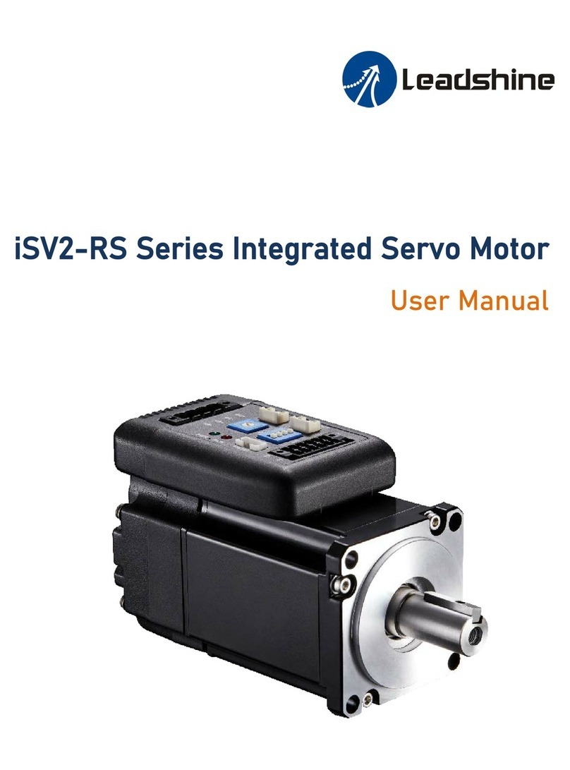
Leadshine iSV-B23 Series Assembly instructions

ii
SafetyItems
!
Caution
Makesurethepowersupplyvoltagedosenotexceedthedrivesinputrange.
Doublechecktheconnectionsand makesurethepowerlead polarityiscorrect.
!
Caution
Disconnectthemotorfromtheloadifyouarenotsurethemovedirectionwhen
performinganymotion.Adjusttheaxisinthemiddlebeforetryingtorunthe
motor.

iii
TableofContents
TableofContents...........................................................................................................................................................iii
Introduction to IntegratedServoMotor ........................................................................................................................1
Applications ....................................................................................................................................................................1
Getting Start ...................................................................................................................................................................2
Wiring Diagrams.....................................................................................................................................................2
Connecting PowerSupply.......................................................................................................................................2
Connecting Motion Controller................................................................................................................................3
Pulse,Direction,EnableInput ........................................................................................................................3
Alarm, In-position Output...............................................................................................................................5
Connecting PC.........................................................................................................................................................5
Configuration..................................................................................................................................................................6
Configuring iSV MotorbyDIPSwitches..................................................................................................................6
Configuring ISV motorinPCSoftware ...................................................................................................................7
Calculating Rotation Speedand Angle...................................................................................................................7
Rotating theiSV Motor...................................................................................................................................................7
Rotating theiSV MotorbyMotion Controller........................................................................................................7
Rotating theISV MotorinSelf-testMode..............................................................................................................7
Rotating theISV MotorinPCSoftware..................................................................................................................7
PowerSupplySelection...................................................................................................................................................8
RegulatedorUnregulatedPowerSupply...............................................................................................................8
MultipleDrives........................................................................................................................................................8
Selecting SupplyVoltage........................................................................................................................................8
RecommendedSupplyVoltage...............................................................................................................................9
Wiring Notes...................................................................................................................................................................9
ControlSignalSetup Timing.........................................................................................................................................10
FineTuning....................................................................................................................................................................10
Protection Functions& indications ...............................................................................................................................11
Over-current Protection........................................................................................................................................12
Over-voltageProtection .......................................................................................................................................12
Position ErrorProtection ......................................................................................................................................12
FrequentlyAskedQuestions.........................................................................................................................................13
ProblemSymptoms and PossibleCauses.....................................................................................................................13
Warranty.......................................................................................................................................................................14
Exclusions..............................................................................................................................................................14
Obtaining WarrantyService.................................................................................................................................14
WarrantyLimitations............................................................................................................................................14
Shipping FailedProduct........................................................................................................................................14
ContactUs.....................................................................................................................................................................15

Hardware installation manualoftheintegrated servo motor
1
IntroductiontoIntegratedServoMotor
LeadshinesiSV-B23xxx integratedservomotorisaNEMA23 brushless motorintegratedwitha1,000-line(4,000
PPR)encoderand aservodrive.Atverycompactsizeandwithall componentsintegrated,theiSV-B23xxx cansave
mountingspace, eliminateencoderconnection&motorwiringtime,reduceinterference,andcut/reducecableand
laborcosts.
Applications
LeadshinesiSV-B23xxx canbeusedin variousapplicationssuchaslasercutters,lasermarkers,highprecision X-Y
tables,labelingmachines,CNC router,etc.ItsuniquefeaturesmaketheiSV-B23xxx anidealchoiceforapplications
thatrequirebothlow-speedsmoothness and small mountingspace.
Drive
Motor
BLDCMotor
Encoder
Amplifier
Comparator
Comp
Command Position
Measured Position
Integrated Servo Motor

Hardware installation manualoftheintegrated servo motor
2
Getting Start
Togetstartyouneedoneintegratedservomotor,oneDCpowersupplyand onemotioncontroller.
Themotioncontrollersuchasindexer,pulsegeneratororPLCisonlyrequiredwhenyouneedto
rotatethemotor.IfyouhaveaPCwithoneserialportorUSB-RS232 converter,youcanalsorotate
themotorinthePCsoftware.Howeveritisrecommendedtoverifythecompletefunctionofthe
integrated easyservo usingamotion controller.
Wiring Diagrams
WiringDiagram of integrated servoiSV-B23xxx
Connecting Power Supply
TheISV-B23XXX acceptsDCpowerinput.Thepowerconnectionsareonlythepositiveand negative
wires. Howeveryouneed topayattentiontowirepolarity.A2-pinpluggablescrewconnectorisused
forpowersupplyconnection.Lookingatthedrivefrontyoushouldfindtheprinted “+Vdc”and
“GND”symbol.Connectthepositivewireto “+Vdc”terminalandconnectthenegativewireto “GND”
terminal.Notethatthepowershouldbeswitchoff whenyoumaketheconnections. Note: Donot
exceedtheinput voltagerangeoftheiSVmotor.Pleaseconsult Power SupplySelection chapter in
themanual fortherecommendedsupplyvoltage.
RS232 Cable
OrUSB-232 Converter
Motion Controller
PowerSupply

Hardware installation manualoftheintegrated servo motor
3
DCpowerconnection of ISV-B23xxx
Connecting Motion Controller
Pulse,Direction,EnableInput
Thepulse,direction and enableinputoftheiSVmotorisdifferential.ItcanalsobeconnectedtoPNP
(sourcing)orNPN(sinking)typecontroller. Fortheenablesignal,apply0VbetweenENA+and ENA-
orleavethemunconnectedtoenabletheiSVmotor.Ifit isneedn ttodisablethedrive,justleave
themunconnected.
In aNPN (sourcing)typeoutput,thecontrolsignals sharethesamepositiveterminalVCC.
iSV-x23xxx
PUL+ 1
DIR+ 3
PUL-
DIR-
2
4
ENA+ 5
ENA- 6
VCC
Step
Direction
Enable
Controller
ControlSignal
Connector
VCC= 5-24V
5Vrecommended
ConnectISV-X23XXX to NPN(sinking)typecontroller
+Vdc
GND
iSV-x23xxx DC Power
+(Positive)
-
(Negative)

Hardware installation manualoftheintegrated servo motor
4
Pulse, Direction, EnableInput(Continued)
In aPNP(sinking)typeoutput,thecontrolsignalsarereferto thesameground terminal.
Controller
Control Signal
Connector
PUL+ 1
DIR+ 3
PUL-
DIR-
2
4
ENA+ 5
ENA- 6
Step
Direction
Enable
VCC
VCC
VCC
VCC=5-24V
5Vrecommended
iSV-x23xxx
ConnectISV-B23XXX to PNP(sourcing)typecontroller
Controller
Control Signal
Connector
PUL+ 1
DIR+ 3
PUL-
DIR-
2
4
ENA+ 5
ENA- 6
5V
Step
Direction
Enable
iSV-x23xxx
ConnectISV-B23XXX to differentialtypecontroller

Hardware installation manualoftheintegrated servo motor
5
Alarm,In-position Output
Theoutputsareisolatedand youcantakethemaselectronicswitch.Anupperresistorneedstobe
usedtolimitthecurrent.Itsresistanceisdependingontheinputcurrentrequirementofthe
controller.Thesupplyvoltageforthoseoutputscanalsobe24V.TheresistorRisdependingonthe
inputcurrentof thecontroller.
ALM+
ALM-
Alarm
Controller
5V
PED+
PED-
In-Position
Control Signal
Connector
RR
iSV-x23xxx
Alarm,in-position signalconnectionof ES-DXXX
Connecting PC
ARS232communicationportisbuiltintotheintegratedservodriveforcommunicationand
configuration.ConnectthisporttothePC sserialport.ThenyoucanturnthemotorinPCsoftware.
Thissoftware-ProTuner,isdesignedtoconfiguretheintegratedservodrive.Youcanconfigurethe
controlmode,stepresolution,currentrateand activelevelof inputs/outputsinProTuner.
TheProTunercanbedownloadedfromourwebsite: http://www.leadshine.com oryoumayalso getit
fromLeadshineCD.Itisrecommendedtogetitfromthewebsitebecauseitisalwaysthelatest.
Install itonyourPCandmakeitreadyforuselater.
ConnectiSV-23130 to PC
ARS232cableisneededforthecommunicationbetweenthedrivesRS232 portandthePC sserial
port.Itwill beshippedwiththekitifyouincludeitintheorder.Itisalsopossibletomakethiscable
yourself.Oneendofthiscableisa5-pinplug-interminalblockand theotherend ofcableisa9pin
D-Sub femaleconnector.IfyourPCdoesnothaveaserialport,aUSB-to-Serialconverterwhich
simulatestheserialportisrequired. Thepowershouldbeturnedoff whenyou performany
Or
RS232 Cable
USB-232 Converter
ProTuner

Hardware installation manualoftheintegrated servo motor
6
connections!
Configuration
Therearenotmuchparametersneedtobeconfiguredfortheintegratedservomotor.Youcan
configureitbytheDIPswitch orPCsoftware.
Configuring iSV Motor byDIPSwitches
A6-bitDIPswitchwhichison sideof thedrivecasecanbeused tosetthepulses/revsetting,motion
directionand activeof pulse.
Pusles/Rev-S1-S4
Pulses/Rev S1 S2 S3 S4
SoftwareConfigured
(Default4000) On
On On On
800 Off
On On On
1600 On
Off
On On
3200 Off
Off
On On
6400 On
On Off
On
12800 Off
On Off
On
25600 On
Off
Off
On
51200 Off
Off
Off
On
1000 On
On On Off
2000 Off
On On Off
4000 On
Off
On Off
5000 Off
Off
On Off
8000 On
On Off
Off
10000 Off
On Off
Off
20000 On
Off
Off
Off
40000 Off
Off
Off
Off
MotorRotationDirection –S5
DIPswitchS5isusedforchangingmotorshaftrotation direction.
Changingpositionfrom “ON”to “OFF”,or “OFF”to “ON”will reverseISV
motor srotationdirection. Self-test –S6
Off:Normalmode.
On:Self-testmode,1revolution CWandthen1revolutionCCW.

Hardware installation manualoftheintegrated servo motor
7
Configuring ISV motor in PCSoftware
Leadshinealreadyloadsdefaultcurrent-loopparametersand position-loopparameters. Thedefault
parametervaluesofthecurrentloophavebeenoptimizedand thereisnoneedtotunethem.
However,youneedtotunethepositionloopparametersforyourapplicationtoachievethebest
performance.Theactualvalueisdeterminedbypowersupplyvoltage,loadinertiaandmotion
profile.
Calculating Rotation Speed and Angle
Youmayalsowanttocalculatethemotorrotation speedand rotationangle,beforecommandingany
motion.If thepulsefrequencyand pulsecountsareknown,theycan becalculatedasfollows:
Rotation Speed (RPM)=60 *Pulse(Step)Frequency/ (Pulse/Rev)
Rotation Angle(°)=360 *Pulse(Step)Counts/ (Pulses/Rev)
Rotating theiSVMotor
Rotating theiSV Motor byMotion Controller
Noweverythingisready.Youcanstartthemotioncontroller(indexer,PLC,pulsegenerator…)to
rotatethemotor.Actually,anyequipmentwhichgiveshigh-to-loworlow-to-highlevelchangescan
beusedtorotatethemotor.Ifitisyourfirsttimeinstallation,itisrecommendedtodisconnectthe
motorshaftfromtheloadincaseofaccident.Youcanstartfromlowpulsefrequencythengoingto
high.Onetriggerededgeofthepulsemakesthemotormoveonemicroangle.Thereisnominimum
speedlimitforiSVmotorhoweverthemaximumrunningspeedwill bedeterminedbytheinput
voltageand currentsetting.
Rotating theISV Motor in Self-testMode
Doublecheckthepowerconnectionand applypowertotheISVmotor.ThegreenLEDshouldbeon.
TheredLEDshouldbeoff.ToggletheSW6to “ON”position.Themotorshaftrotates1revolutions
CWandthen1revolutionsCCW.ItrepeatsuntilS6issettothe “Off”position(themotorshaftwill
stop immediately).
Rotating theISV Motor inPCSoftware
ThereisasimpleemulatingcontrollerbuiltinsideProTuner.Itisnotafullfunctionalitycontrollerbut
itisusefulwhenyoudonothaveamotioncontrollerrotatethemotor.Youcanspecifythespeed,
accelerationandmovedistanceforamotion. However,theperformanceintheemulatingcontroller
ofthePCsoftwareCANNOTrepresenttheactualmotion controller.Refertothesoftwaremanual

Hardware installation manualoftheintegrated servo motor
8
formoreinformation.
PowerSupplySelection
Toachievegooddrivingperformances,itisimportanttochooseasuitablesupplyvoltageandusea
matchingcurrentvalue.Generallyspeaking,supplyvoltagedeterminesthehighspeedperformance
ofthemotor,whileoutputcurrentdeterminestheoutputtorqueof thedriven motor(particularlyat
lowerspeed).Highersupplyvoltagewillallowhighermotorspeedtobeachieved,atthepriceof
morenoiseand heating. Ifthemotionspeedrequirementislow,it sbettertouselowersupply
voltageto decreasenoise,heatingand improvereliability.
Regulated or UnregulatedPower Supply
Bothregulatedandunregulatedpowersuppliescanbeusedtosupplythedrive.Ifregulatedpower
supplies(suchasmostswitchingsupplies.)areindeedused,itisimportanttohavelargecurrent
outputratingtoavoidproblemslikecurrentclamp,forexampleusing4Asupplyfor3Amotor-drive
operation.Ontheotherhand,ifunregulatedsupplyisused,onemayuseapowersupplyoflower
currentratingthan thatofmotor(typically50% 70%of motorcurrent).Thereasonisthatthedrive
drawscurrentfromthepowersupplycapacitoroftheunregulatedsupplyonlyduringtheON
durationofthePWMcycle,butnotduringtheOFF duration.Therefore,theaveragecurrent
withdrawnfrompowersupplyisconsiderablyless thanmotorcurrent.Forexample,two3Amotors
can bewell supplied byonepowersupplyof 4Arating.
MultipleDrives
Itisrecommendedtohavemultipledrivestoshareonepowersupplytoreducecost,ifthesupply
hasenoughcapacity.Toavoidcross interference,DONOTdaisy-chainthepowersupplyinputpinsof
thedrives. Instead,pleaseconnectthemto powersupplyseparately.
Selecting SupplyVoltage
Highersupplyvoltagecanincreasemotortorqueathigherspeeds,thushelpfulforavoidinglosing
steps. However,highervoltagemaycausebiggermotorvibrationatlowerspeed,anditmayalso
causeover-voltageprotectionorevendrivedamage.Therefore,itissuggestedtochooseonly
sufficientlyhighsupplyvoltageforintendedapplications,and itissuggestedtousepowersupplies
withtheoreticaloutputvoltageofdrivesminimum+10%todrivesmaximum –10%,leavingroom
forpowerfluctuation and back-EMF.

Hardware installation manualoftheintegrated servo motor
9
SelectPowerSupplyVoltage
DriverInputVoltage
DriverUpperInput limit
PowerSupplyVoltage
Heating
Vibration
MaximumSafeRating
DriverUpperInput limit 10%
DriverLowerInputlimit +10%
DriverLowerInputlimit
MinimumSafeRating
Torque
Speed
SafeRegion
DriverInputVoltage
DriverUpperInput limit
PowerSupplyVoltage
Heating
Vibration
MaximumSafeRating
DriverUpperInput limit 10%
DriverLowerInputlimit +10%
DriverLowerInputlimit
MinimumSafeRating
Torque
Speed
SafeRegion
Recommended SupplyVoltage
BothLeadshinesregulatedand unregulatedpowersupplyhasbeendesignedspeciallyformotion
control.
Model InputVoltageRange TypicalVoltage LeadshinePowerSupply
ISV-B23090 DC(20-50)V DC36V RPS369
ISV-B23130 DC(20-50)V DC36V RPS369
ISV-B23180 DC(20-50)V DC36V RPS369
Wiring Notes
lIn orderto improveanti-interferenceperformanceof thedrive,itisrecommendedto usetwisted
pair shield cable.
lTopreventnoiseincurredinPUL/DIRsignal,pulse/directionsignalwiresand motorwiresshould
notbetiedup together.Itisbettertoseparatethembyatleast10 cm,otherwisethedisturbing
signalsgeneratedbymotorwilleasilydisturbpulsedirectionsignals, causingmotorposition
error,systeminstabilityand otherfailures.
lIfapowersupplyservesseveraldrives,separatelyconnectingthedrivesisrecommendedinstead
of daisy-chaining.
lItisprohibitedtopull and plugpowerconnectorwhilethedriveispoweredON,becausethereis
highcurrentflowingthroughmotorcoils(evenwhenmotorisatstandstill).Pullingorplugging
powerconnectorwithpoweronwill causeextremelyhighback-EMFvoltagesurge,whichmay
damagethedrive.

Hardware installation manualoftheintegrated servo motor
10
ControlSignalSetupTiming
Tomakeareliableoperation,theISVmotorrequiresthecontrolsignalstomeetthesetup time
requirementsasfollows. Otherwiselosingof stepsmayhappen.
FineTuning
Leadshinealreadyloadsdefaultcurrent-loopparametersand position-loopparameters. Thedefault
parametervaluesofthecurrentloophavebeenoptimizedand thereisnoneedtotunethem.
However,youneedtotunethepositionloopparametersforyourapplicationtoachievethebest
performance.Theactualvalueisdeterminedbypowersupplyvoltage,loadinertiaandmotion
profile.
ControlSignalSetupTime
Drive Frequency tDS tPHS/ tPLS tDD tES tED
ISV-B23090 200K/ 500K 5us >2.5us/ >1.0us 5us 1ms 1ms
ISV-B23130 200K/ 500K 5us >2.5us/ >1.0us 5us 1ms 1ms
ISV-B23180 200K/ 500K 5us >2.5us/ >1.0us 5us 1ms 1ms
Symbol
Description
tDS Direction Setup Time
tPHS PulseHighLevelSetup Time
tPLS PulseLowLevelSetup Time
tDD Direction Delay Time
tES EnableSetup Time
tED EnableDelay Time

Hardware installation manualoftheintegrated servo motor
11
Protection Functions&indications
Toimprovereliability,theIESincorporatessomebuilt-in protection functions. TheIntegratedstepper
usesoneredLEDtoindicatetheprotectiontype.Theperiodictimeofredis4s(seconds),and the
blinkingtimesofredLEDindicateswhatprotectionhasbeenactivated.Becauseonlyoneprotection
can bedisplayedbyred LED,so thedrivewilldecidewhaterrortodisplayaccordingto their priorities.
See thefollowingProtection Indicationstablefordisplayingpriorities.
Priority
Time(s)of
Blink SequencewaveofredLED Description
1st 1 Over-currentprotection activatedwhenpeak
currentisgreaterthan18A
2nd 2 Over-voltageprotection activatedwhendrive
workingvoltageisgreaterthan60VDC
3rd 5 Encodererroractivatedwhenencoderconnection
orfeedback isnotcorrect
4th 7
Position followingerroractivatedwhenposition
followingerrorlimitexceededthepre-setvalue
(4000 pulsesby default, orvaluesetvalueby a
customer)

Hardware installation manualoftheintegrated servo motor
12
ProtectionFunctions&indications(Continued)
Over-currentProtection
Over-currentprotectionwillbeactivatedwhencontinuouscurrentexceeds18Aorincaseofshort
circuitbetweenmotorcoilsorbetweenmotorcoil andground,andREDLEDwillblinkoncewithin
each periodictime.
Over-voltageProtection
Whenpowersupplyvoltageexceeds60VDC,protectionwillbeactivatedand redLEDwill blinktwice
within eachperiodictime.
!
Caution
Whenaboveprotectionsareactive,themotorshaftwillbefree ortheLEDwillblink.Reset
thedrive byrepoweringittomakeitfunctionproperlyafterremovingaboveproblems. Since
thereisnoprotection againstpowerleads(﹢,﹣)reversal,itiscriticaltomakesurethat
powersupplyleadscorrectlyconnectedtodrive.Otherwise,thedrive will bedamaged
instantly.
Position Error Protection
Whenthepositionerrorexceedsthelimit(softwareconfigurable,see softwaremanual),position,
protection will beactivated and redLEDwill blinkseven timeswithin eachperiodictime.

Hardware installation manualoftheintegrated servo motor
13
FrequentlyAskedQuestions
In theeventthatyourdrivedoesn toperateproperly,thefirststepisto identifywhethertheproblem
iselectricalormechanicalinnature.Thenextstepistoisolatethesystemcomponentthatiscausing
theproblem.Aspartofthisprocess youmayhavetodisconnecttheindividualcomponentsthat
makeup yoursystemand verifythattheyoperateindependently.Itisimportanttodocumenteach
stepinthetroubleshootingprocess. Youmayneedthisdocumentationtoreferbacktoatalaterdate,
and thesedetailswill greatlyassistourTechnicalSupportstaff in determiningtheproblemshouldyou
need assistance.
Manyoftheproblemsthataffectmotioncontrolsystemscanbetracedtoelectricalnoise,controller
softwareerrors, ormistakeinwiring.
ProblemSymptomsand PossibleCauses
Symptoms PossibleProblems
Nopower
Stepresolution settingiswrong
Faultcondition exists
Motorisnotrotating
Thedrive isdisabled
Motorrotatesinthe
wrongdirection TheDirection signallevelisreverse
Powersupply voltagebeyond drivesinputrange
SomethingwrongwithmotorcoilThedriveinfault Wrongconnection
Control signalistoo weak
Control signalisinterfered
Somethingwrongwithmotorcoil
Motorisundersizedfortheapplication
Acceleration issettoo high
Erraticmotormotion
Powersupply voltagetoo low
Inadequateheatsinking/cooling
Excessivemotorand
driveheating Loadistoo high

Hardware installation manualoftheintegrated servo motor
14
Warranty
LeadshineTechnologyCo.,Ltd.warrantsitsproductsagainstdefectsinmaterialsandworkmanship
foraperiodof12 monthsfromshipmentoutoffactory.Duringthewarrantyperiod,Leadshinewill
either,atitsoption,repairorreplaceproductswhich proved to bedefective.
Exclusions
Theabovewarrantydoesnotextendtoanyproductdamagedbyreasonsofimproperorinadequate
handlings bycustomer,improperorinadequatecustomerwirings,unauthorizedmodificationor
misuse,oroperationbeyondtheelectricalspecificationsoftheproductand/oroperationbeyond
environmentalspecificationsfortheproduct.
Obtaining WarrantyService
Toobtainwarrantyservice,areturnedmaterialauthorizationnumber(RMA)mustbeobtainedfrom
customerserviceate-mail:beforereturningproductforservice.Customershall prepayshipping
chargesforproductsreturnedto Leadshineforwarrantyservice,andLeadshineshallpayforreturnof
productsto customer.
WarrantyLimitations
Leadshinemakesnootherwarranty,eitherexpressedorimplied,withrespecttotheproduct.
Leadshinespecificallydisclaimstheimpliedwarrantiesofmerchantabilityand fitness foraparticular
purpose.Somejurisdictionsdonotallowlimitationsonhowlongandimpliedwarrantylasts,sothe
abovelimitationorexclusionmaynotapplytoyou.However,anyimpliedwarrantyof
merchantabilityorfitness islimited to the12-month duration of thiswritten warranty.
Shipping Failed Product
Ifyourproductfail duringthewarrantyperiod,e-mailcustomerserviceattoobtainareturned
materialauthorizationnumber(RMA)beforereturningproductforservice.Pleaseincludeawritten
descriptionoftheproblemalongwithcontactnameandaddress. Sendfailedproducttodistributor
inyourareaor: ULeadshineTechnologyCo.,Ltd.3/F,Block2,NanyouTiananIndustrialPark,Nanshan
Dist,Shenzhen,China.UAlsoencloseinformationregardingthecircumstancespriortoproduct
failure.

Hardware installation manualoftheintegrated servo motor
15
Contact Us
ChinaHeadquarters
Address: 3/F,Block2,NanyouTianan IndustrialPark,NanshanDistrictShenzhen,China
Web: http://www.leadshine.com
SalesHot Line:
Tel: 86-755-2641-7674 (forAsia,Australia,Africaareas)
86-755-2640-9254(forEuropeareas)
86-755-2641-7617(forAmericaareas)
Fax: 86-755-2640-2718
Email: sales@leadshine.com.
Technical Support:
Tel: 86-755-2641-8447,86-755-2641-8774,86-755-2641-0546
Fax: 86-755-2640-2718
Email: tech@leadshine.com(for All)
LeadshineU.S.A
Address: 25 Mauchly,Suite318 Irvine,California92618
Tel: 1-949-608-7270
Fax: 1-949-608-7298
Web: http://www.leadshineUSA.com
Email: sales@leadshineUSA.com and support@leadshineUSA.com.
This manual suits for next models
3
Table of contents
Other Leadshine Engine manuals
Popular Engine manuals by other brands
Nidec
Nidec LA16G324B50MC quick reference

Kohler
Kohler Confidant ZT710 Service manual
Texas Instruments
Texas Instruments Stellaris user manual

Skov
Skov DA 74C Series Technical user guide
Briggs & Stratton
Briggs & Stratton 400000 Professional Series operating & maintenance manual
YARDMAX
YARDMAX LC1P65FE-2 Operator's manual

