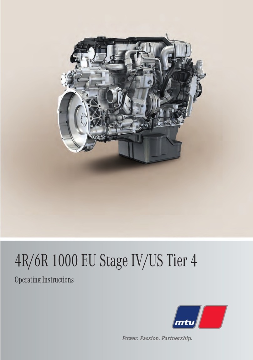
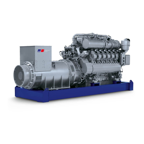
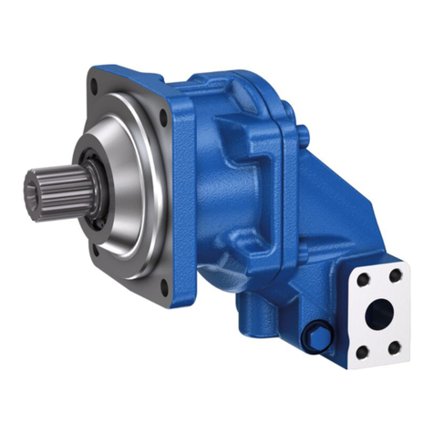
MTU 8V1600 G10F User manual

Operating InstructionsOperating Instructions
Diesel engineDiesel engine
8, 10, 12 V 1600 G10F, G20F8, 10, 12 V 1600 G10F, G20F
8, 10, 12 V 1600 G40F, G50F8, 10, 12 V 1600 G40F, G50F
8, 10, 12 V 1600 G70F, G80F8, 10, 12 V 1600 G70F, G80F
8, 12 V 1600 B30S8, 12 V 1600 B30S
8, 10 V 1600, B40S, B50F8, 10 V 1600, B40S, B50F
12 V 1600, B40S12 V 1600, B40S
8, 10, 12 V 1600 G10S, G20S8, 10, 12 V 1600 G10S, G20S
8, 10, 12 V 1600 G70S, G80S8, 10, 12 V 1600 G70S, G80S
MS150076/05EMS150076/05E

Printed in GermanyPrinted in Germany
© 2014 Copyright MTU Friedrichshafen GmbH© 2014 Copyright MTU Friedrichshafen GmbH
This Publication is protected by copyright and may not be used in any way whether in whole or in part without the priorThis Publication is protected by copyright and may not be used in any way whether in whole or in part without the prior
written permission of MTU Friedrichshafen GmbH. This restriction also applies to written permission of MTU Friedrichshafen GmbH. This restriction also applies to
copyright, distribution, translation, mi-copyright, distribution, translation, mi-
crofilming and storage or processing on electronic crofilming and storage or processing on electronic
systems including data bases and online services.systems including data bases and online services.
This handbook is provided for use by maintenance and This handbook is provided for use by maintenance and
operating personnel in order to avoid malfunctions or operating personnel in order to avoid malfunctions or
damagedamage
during operation.during operation.
Subject to alterations and amendments.Subject to alterations and amendments.

Table of ContentsTable of Contents
11
SS
aa
ff
ee
tt
yy
11
..
11
II
mm
pp
oo
rr
tt
aa
nn
t t
pp
rr
oo
vv
ii
ss
ii
oo
nn
s s
ff
oo
r r
aa
ll
l l
pp
rr
oo
dd
uu
cc
tt
ss
55
11
..
22
PP
ee
rsrs
oo
nn
nn
ee
l anl an
d od o
rgrg
aa
nn
ii
zz
aa
tt
ioio
nn
aa
l rel re
qq
uu
ii
rr
ee
mm
ee
nn
tt
ss
66
11
..
33
TT
rr
aa
nn
ss
pp
oo
rr
tt
77
1.41.4
Safety Safety
regularegula
tions tions
for mafor ma
inteninten
ance aance a
ndnd
rr
ee
pp
aa
ii
r r
ww
oo
rr
kk
88
1.51.5
Fire pFire p
revenreven
tion tion
and enand en
vironviron
mentamenta
ll
protection, fluids and lubricants, auxiliaryprotection, fluids and lubricants, auxiliary
mm
aa
tt
ee
rr
ii
aa
ll
ss
11
11
11
..
66
SS
tt
aa
nn
dd
aa
rr
dd
s s
ff
oo
r r
ss
aa
ff
ee
tt
y y
nn
oo
tt
ii
cc
ee
s s
ii
n n
tt
hh
e e
tt
ee
xx
tt
11
33
22
GenGen
eraera
l Il I
nfonfo
rmarma
tiotio
nn
22
..
11
EE
nn
gg
ii
nn
e e
ll
aa
yy
oo
uu
tt
11
44
22
..
22
EE
nn
gg
ii
nn
e e
ss
ii
dd
e e
aa
nn
d d
cc
yy
ll
ii
nn
dd
ee
r r
dd
ee
ss
ii
gg
nn
aa
tt
ii
oo
nn
ss
11
55
22
..
33
SS
ee
nn
ss
oo
rr
s s
aa
nn
d d
aa
cc
tt
uu
aa
tt
oo
rr
s s
– –
OO
vv
ee
rr
vv
ii
ee
ww
11
66
33
TeTe
chch
nini
caca
l Dl D
atat
aa
3.13.1
8/10/18/10/1
2V 162V 16
00 G100 G1
0F/G20F 0F/G20F
enginengin
e date dat
a,a,
ee
mm
ii
ss
ss
ii
oo
nn
ss
--
oo
pp
tt
ii
mm
ii
zz
ee
dd
11
88
3.23.2
8V/10V8V/10V
/12V 1/12V 1
600 G1600 G1
0F/G200F/G20
F engiF engi
ne dane da
ta,ta,
oo
pp
tt
ii
mm
ii
zz
ee
d d
ff
uu
ee
l l
cc
oo
nn
ss
uu
mm
pp
tt
ii
oo
nn
22
22
3.33.3
8V/10V8V/10V
/12V 1/12V 1
600 G1600 G1
0F/G200F/G20
F engiF engi
ne dane da
ta,ta,
EE
U U
NN
oo
nn
rr
oo
aa
d d
SS
tt
aa
gg
e e
II
II
I I
AA
22
66
3.43.4
8V/10V8V/10V
/12V 1/12V 1
600 G1600 G1
0S/G200S/G20
S engiS engi
ne dane da
ta,ta,
EE
PP
A A
TT
ii
ee
r r
22
, ,
33
33
00
3.53.5
8/10/18/10/1
2V 162V 16
00 G700 G7
0F/G80F 0F/G80F
enginengin
e date dat
a,a,
ee
mm
ii
ss
ss
ii
oo
nn
ss
--
oo
pp
tt
ii
mm
ii
zz
ee
dd
33
33
3.63.6
10/12V 10/12V
1600 1600
G70F/GG70F/G
80F e80F e
ngine ngine
data,data,
oo
pp
tt
ii
mm
ii
zz
ee
d d
ff
uu
ee
l l
cc
oo
nn
ss
uu
mm
pp
tt
ii
oo
nn
33
77
3.73.7
8/10V 8/10V
1600 1600
G70F/GG70F/G
80F e80F e
ngine ngine
data, data,
EUEU
NN
oo
nn
rr
oo
aa
d d
SS
tt
aa
gg
e e
II
II
I I
AA
44
11
3.3.
88
8/8/
1212
V 1V 1
6060
0 G0 G
7070
S eS e
ngng
inin
e de d
atat
a, a,
EPEP
A TA T
ieie
r 2r 2
, 3, 3
4444
3.93.9
8/10/18/10/1
2V 1600 2V 1600
G80S enG80S en
gine dgine d
ata, EPata, EP
A TierA Tier
22
, ,
33
44
77
3.103.10
8/10/18/10/1
2V 1602V 160
0 G40F/0 G40F/
G50F eG50F e
ngine ngine
data,data,
ee
mm
ii
ss
ss
ii
oo
nn
ss
--
oo
pp
tt
ii
mm
ii
zz
ee
dd
55
11
3.113.11
8/10/18/10/1
2V 1602V 160
0 G40F/0 G40F/
G50F eG50F e
ngine ngine
data,data,
oo
pp
tt
ii
mm
ii
zz
ee
d d
ff
uu
ee
l l
cc
oo
nn
ss
uu
mm
pp
tt
ii
oo
nn
55
55
3.123.12
8/10V 8/10V
1600 G1600 G
40F/G540F/G5
0F eng0F eng
ine daine da
ta, EUta, EU
NN
oo
nn
rr
oo
aa
d d
SS
tt
aa
gg
e e
II
II
I I
AA
55
99
33
..
11
33
88
//
11
22
V V
11
66
00
0 0
BB
33
00
S S
ee
nn
gg
ii
nn
e e
dd
aa
tt
aa
66
22
3.143.14
8/10/18/10/1
2V 12V 1
600 600
B40S B40S
engine engine
data,data,
ss
ww
ii
tt
cc
hh
aa
bb
ll
e e
ff
rr
ee
qq
uu
ee
nn
cc
yy
66
55
3.153.15
10V 1610V 16
00 B5000 B50
F engiF engi
ne dane da
ta, eta, e
missiomissio
ns-ns-
oo
pp
tt
ii
mm
ii
zz
ee
dd
66
99
3.163.16
10V 16010V 160
0 B50F e0 B50F e
ngine ngine
data, odata, o
ptimiptimi
zed fuzed fu
elel
cc
oo
nn
ss
uu
mm
pp
tt
ii
oo
nn
77
22
3.173.17
10V 1610V 16
00 B500 B5
0F eng0F eng
ine daine da
ta, Eta, E
U NonrU Nonr
oadoad
SS
tt
aa
gg
e e
II
II
II
AA
77
55
33
..
11
88
FF
ii
rr
ii
nn
g g
oo
rr
dd
ee
rr
77
88
33
..
11
99
EE
nn
gg
ii
nn
e e
– –
MM
aa
ii
n n
dd
ii
mm
ee
nn
ss
ii
oo
nn
ss
77
99
44
OpOp
erer
atat
ioio
nn
4.14.1
PuttPutt
ing the eing the e
ngine ingine i
nto opnto op
eratierati
on afton aft
erer
exex
tete
ndnd
ed ed
ouou
t-t-
ofof
-s-s
erer
vivi
ce ce
pepe
riri
odod
s (s (
>3 >3
momo
ntnt
hshs
))
8080
4.24.2
PuttPutt
ing the eing the e
ngine ingine i
nto opnto op
eratierati
on afton aft
erer
ss
cc
hh
ee
dd
uu
ll
ee
d od o
uu
tt
--
oo
ff
--
ss
ee
rr
vv
ii
cc
ee
--
pp
ee
rr
ii
oo
dd
88
11
44
..
33
EE
nn
gg
ii
nn
e e
ss
tt
aa
rr
t t
ii
n n
mm
aa
nn
uu
aa
l l
oo
pp
ee
rr
aa
tt
ii
oo
n n
((
tt
rr
ii
aa
ll
ss
))
88
22
44
..
44
SS
aa
ff
ee
tt
y y
ss
yy
ss
tt
ee
m m
– –
OO
vv
ee
rr
rr
ii
dd
ee
88
33
44
..
5 O5 O
pp
ee
rr
aa
tt
ii
oo
nn
aa
l l
cc
hh
ee
cc
kk
ss
88
44
44
..
66
EE
nn
gg
ii
nn
e e
ss
tt
oo
p p
ii
n n
mm
aa
nn
uu
aa
l ol o
pp
ee
rr
aa
tt
ii
oo
n n
((
tt
rr
ii
aa
ll
ss
))
88
55
44
..
77
EE
mm
ee
rr
gg
ee
nn
cc
y y
ss
tt
oo
pp
88
66
4.84.8
AfteAfte
r stoppr stopp
ing the eing the e
ngine – Engine – E
ngine rngine r
emainemain
ss
rr
ee
aa
dd
y y
ff
oo
r r
oo
pp
ee
rr
aa
tt
ii
oo
nn
88
77
4.94.9
AfteAfte
r stopr stop
ping tping t
he enhe en
gine – gine –
PuttiPutti
ng theng the
ee
nn
gg
ii
nn
e e
oo
uu
t t
oo
f f
oo
pp
ee
rr
aa
tt
ii
oo
nn
88
88
55
MaMa
inin
tete
nana
ncnc
ee
55
..
11
MM
aa
ii
nn
tt
ee
nn
aa
nn
cc
e e
aa
nn
d d
ss
ee
rr
vv
ii
cc
ii
nn
gg
88
99
55
..
22
MM
aa
ii
nn
tt
ee
nn
aa
nn
cc
e e
tt
aa
ss
k k
rr
ee
ff
ee
rr
ee
nn
cc
e e
tt
aa
bb
ll
ee
99
00
66
TroTro
ubub
lele
shsh
oooo
titi
ngng
66
..
11
TT
rr
oo
uu
bb
ll
ee
ss
hh
oo
oo
tt
ii
nn
gg
99
11
77
TaTa
sk Desk De
scsc
riri
ptpt
ioio
nn
77
..
11
EE
nn
gg
ii
nn
ee
99
33
77
..
11
..
11
EE
nn
gg
ii
nn
e e
– –
BB
aa
rr
rr
ii
nn
g g
ww
ii
tt
h h
ss
tt
aa
rr
tt
ii
nn
g g
ss
yy
ss
tt
ee
mm
99
33
77
..
11
..
2 E2 E
nn
gg
ii
nn
e e
– –
TT
ee
ss
t t
rr
uu
nn
99
44
77
..
22
VV
aa
ll
vv
e e
DD
rr
ii
vv
ee
99
55
77
..
22
..
11
VV
aa
ll
vv
e e
cc
ll
ee
aa
rr
aa
nn
cc
e e
– –
CC
hh
ee
cc
k k
aa
nn
d d
aa
dd
jj
uu
ss
tt
mm
ee
nn
tt
99
55
7.2.27.2.2
CylinCylin
der heder he
ad covad cov
er – Remer – Rem
oval oval
andand
ii
nn
ss
tt
aa
ll
ll
aa
tt
ii
oo
nn
99
88
77
..
33
FF
uu
ee
l l
SS
yy
ss
tt
ee
mm
99
99
77
..
33
..
11
FF
uu
ee
l l
ss
yy
ss
tt
ee
m m
– –
VV
ee
nn
tt
ii
nn
gg
99
99
77
..
44
FF
uu
ee
l l
FF
ii
ll
tt
ee
rr
11
00
00
77
..
44
..
11
FF
uu
ee
l l
ff
ii
ll
tt
ee
r r
– –
RR
ee
pp
ll
aa
cc
ee
mm
ee
nn
tt
11
00
00
77
..
44
..
22
FF
uu
ee
l l
pp
rr
ee
ff
ii
ll
tt
ee
r r
– –
RR
ee
pp
ll
aa
cc
ee
mm
ee
nn
tt
11
00
11
77
..
55
AA
ii
r r
FF
ii
ll
tt
ee
rr
11
00
22
77
..
55
..
11
AA
ii
r r
ff
ii
ll
tt
ee
r r
‒ ‒
RR
ee
pp
ll
aa
cc
ee
mm
ee
nn
tt
11
00
22
77
..
55
..
22
AA
ii
r r
ff
ii
ll
tt
ee
r r
– –
RR
ee
mm
oo
vv
aa
l l
aa
nn
d d
ii
nn
ss
tt
aa
ll
ll
aa
tt
ii
oo
nn
11
00
33
77
..
66
AA
ii
r r
II
nn
tt
aa
kk
ee
11
00
44
7.7.
6.6.
11
SeSe
rvrv
icic
e e
inin
didi
caca
toto
r r
– –
SiSi
gngn
al al
riri
ng ng
popo
sitsit
ioio
n n
chch
ecec
kk
1010
44
MS150076/05E 2014-02MS150076/05E 2014-02
||
TT
aa
bb
ll
e e
oo
f f
CC
oo
nn
tt
ee
nn
tt
ss
||
33
DD
CC
LL
--
II
DD
::
00
00
00
00
00
00
11
88
00
55
--
00
00
77

7
.
7 S
t
a
r
t
i
n
g
E
q
u
i
p
m
e
n
t
1
0
5
7
.
7
.
1
S
t
a
r
t
e
r
–
C
o
n
d
i
t
i
o
n
c
h
e
c
k
1
0
5
7
.
8
L
u
b
e
O
i
l
S
y
s
t
e
m
,
L
u
b
e
O
i
l
C
i
r
c
u
i
t
1
0
6
7
.
8
.
1
E
n
g
i
n
e
o
i
l
–
L
e
v
e
l
c
h
e
c
k
1
0
6
7
.
8
.
2
E
n
g
i
n
e
o
i
l
–
C
h
a
n
g
e
1
0
7
7
.
9
O
i
l
F
i
l
t
r
a
t
i
o
n
/
C
o
o
l
i
n
g
1
0
8
7
.
9
.
1
E
n
g
i
n
e
o
i
l
f
i
l
t
e
r
–
R
e
p
l
a
c
e
m
e
n
t
1
0
8
7.10
Coolan
t Circu
it, Gen
eral, Hi
gh-Tem
perat
ure
C
i
r
c
u
i
t
1
0
9
7
.
1
0
.
1
E
n
g
i
n
e
c
o
o
l
a
n
t
–
L
e
v
e
l
c
h
e
c
k
1
0
9
7
.
1
0
.
2
E
n
g
i
n
e
c
o
o
l
a
n
t
–
C
h
a
n
g
e
1
1
0
7
.
1
0
.
3
E
n
g
i
n
e
c
o
o
l
a
n
t
–
D
r
a
i
n
i
n
g
1
1
1
7
.
1
0
.
4
E
n
g
i
n
e
c
o
o
l
a
n
t
–
F
i
l
l
i
n
g
1
1
2
7
.
1
0
.
5
E
n
g
i
n
e c
o
o
l
a
n
t p
u
m
p –
R
e
l
i
e
f b
o
r
e
c
h
e
c
k
1
1
4
7
.
1
1
B
e
l
t
D
r
i
v
e
1
1
5
7
.
1
1
.
1
D
r
i
v
e
b
e
l
t
–
A
d
j
u
s
t
m
e
n
t
1
1
5
7
.
1
1
.
2
D
r
i
v
e
b
e
l
t
–
C
o
n
d
i
t
i
o
n
c
h
e
c
k
1
1
6
7
.
1
1
.
3
D
r
i
v
e
b
e
l
t
–
T
e
n
s
i
o
n
c
h
e
c
k
1
1
7
7
.
1
1
.
4
D
r
i
v
e
b
e
l
t
–
R
e
p
l
a
c
e
m
e
n
t
1
1
9
7.
12
Wi
ri
ng
(G
en
er
al
)
fo
r
En
gi
ne
/G
ea
rb
ox
/U
ni
t
12
1
7
.
1
2
.
1
E
n
g
i
n
e
w
i
r
i
n
g
–
C
h
e
c
k
1
2
1
7.13
Acces
sorie
s for
(Elec
troni
c) Eng
ine
G
o
v
e
r
n
o
r
/
C
o
n
t
r
o
l
S
y
s
t
e
m
1
2
2
7.
1
3.
1
En
g
in
e g
ov
er
no
r a
nd
co
n
ne
ct
or
s – C
l
ea
ni
ng
12
2
7.
13
.2
En
gi
ne
go
ve
rn
or
– C
he
ck
in
g p
lu
g c
on
ne
ct
io
ns
12
3
8
Ap
p
en
di
x A
8
.
1
A
b
b
r
e
v
i
a
t
i
o
n
s
1
2
4
8
.
2
M
T
U
c
o
n
t
a
c
t
p
e
r
s
o
n
s
/
s
e
r
v
i
c
e
p
a
r
t
n
e
r
s
1
2
7
9
Ap
p
en
di
x B
9
.
1
S
p
e
c
i
a
l
T
o
o
l
s
1
2
8
9
.
2
I
n
d
e
x
1
3
1
4
|
T
a
b
l
e
o
f
C
o
n
t
e
n
t
s
|
MS150076/05E 2014-02
D
C
L
-
I
D
:
0
0
0
0
0
0
1
8
0
5
-
0
0
7

1
S
a
f
e
t
y
1.
1
Im
po
rt
an
t pr
ov
is
io
ns
fo
r a
ll
pr
od
uc
ts
Nameplate
The product is identified by nameplate, model designation or serial number and
must match with the
information on the title page of
this manual.
Nameplate, model designation or serial number can be found on
the product.
General information
This product may pose a risk
of injury or damage in
the following cases:
•
In
cor
re
ct us
e
•
Operation, ma
intenance and
repair by
unqualified
personnel
•
Modi
ficat
ions o
r conv
ersio
ns
•
Noncompliance
with the
safety instructi
ons and
warning notices
Correct use
The product is intended exclusively for the application specified in the contract
or defined at the time
of
delivery.
This means that the equipment must be
operated:
•
Within the permi
ssible operating
parameters in accordance
with the (→ Technical
data)
•
With fluids and lub
ricants approved by the manu
facturer in accordance with the (→ Flu
ids and Lubri-
cants Specifications of the manufacturer)
•
With spare parts
approved by
the manufacturer in
accordance with the
(→ Spare Parts Catalog
/MTU
contact/Service partner)
•
In the original as-deliv
ered configuration or in a config
uration approved by the m
anufacturer in writ-
ing (including engine control/parameters)
•
In compliance with all saf
ety regulations and in adhere
nce with all warning notices in t
his manual
•
In accordance with
the maintenance requ
irements over the
entire service l
ife of the prod
uct (→ Main-
tenance Schedule)
•
In compliance wi
th the maintenance and
repair instructions contai
ned in this manu
al, in particular
with regard to the specified tightening torques
•
With the exclusiv
e use of techni
cal personnel trained
in commissioning, ope
ration, maintenance and
repair
•
By contracting only
workshops authorized
by the manufacture
r to carry out rep
air and overhaul
Any other use is co
nsidered improper use and increases the risk of personnel injury
or material damage
in product operation. The manufacturer will accept no
liability for such damage.
Modifications or conversions
Unauthorized modifications to the product compromise safety.
The manufacturer will accept no liability or warranty
claims for any damage caused by unauthorized
modifications or conversions.
Spare parts
Only genuine spare parts must be used to
replace components or assemblies.
The manufacturer will accept no liability or warranty
claims for any damage caused by the
use of other
spare parts.
MS150076/05E 2014-02
|
S
a
f
e
t
y
|
5
T
I
M
-
I
D
:
0
0
0
0
0
4
0
5
3
0
-
0
0
3

1.
2
Pe
rs
onn
el an
d org
an
iz
at
io
na
l req
ui
re
me
nts
Organizational measures of the operator
This manual must be issued to
all personnel involved in operation, maintenance, repair or transporta-
tion.
Keep this manual handy in the
vicinity of the product such that it
is accessible to operating, mainte-
nance, repair and transport personnel at
all times.
Use this manual as a
basis for instructing personnel on product operation and
repair, whereby the safe-
ty-relevant instructions, in particular, must be read and understood.
This is particularly important in the case of personnel who only occasionally perform work on or around
the product. This personnel must be instructed repeatedly.
Personnel requirements
All work on the product
shall be carried out by trained and
qualified personnel only.
•
Train
ing at the Train
ing Cent
er of the manuf
acture
r
•
Qualified
personnel special
ized in
mechanical and
plant engineeri
ng
The operator must define the responsibilities of the personnel involved in
operation, maintenance, re-
pair and transport.
Working clothes and personal protective e
quipment
Wear proper protective clothing for all work.
When working, always wear the necessary personal protective equipment (e.g. ear
protectors, protec-
tive gloves, goggles, breathing protection). Observe the information on personal protective equipment
in the respective activity
description.
6
|
S
a
f
e
t
y
|
MS150076/05E 2014-02
T
I
M
-
I
D
:
0
0
0
0
0
4
0
5
3
1
-
0
0
2

1
.
3
T
r
a
n
s
p
o
r
t
Transport
Lift the engine only with the
lifting eyes provided.
Use only the transport and
lifting equipment approved by MTU.
Take note of the engine center
of gravity.
The engine must only be transported in
installation position, max. permissible diagonal pull 10°.
In the case of
special packaging with aluminum foil, suspend the engine on the lifting eyes of
the trans-
port pallet or transport with equipment for
heavy loads (forklift truck).
Setting the engine down after transport
Place the engine only on an even, firm surface.
Ensure appropriate consistency and load-bearing capacity of the ground or
support surface.
Never place an engine on the oil
pan, unless expressively authorized by MTU on a case-to-case basis
to
do so.
MS150076/05E 2014-02
|
S
a
f
e
t
y
|
7
T
I
M
-
I
D
:
0
0
0
0
0
0
0
8
7
2
-
0
0
3

1.4
Saf
ety
reg
ulat
ion
s f
or
mai
nte
nan
ce
and
rep
air
wor
k
Safety regulations prior to maintenance and repair work
Have maintenance or repair work carried out
by qualified and authorized personnel only.
Allow the product to cool
down to less than 50°C
before starting maintenance work (risk of explosion
of oil vapors, fluids and lubricants, risk of
burning).
Before starting work, relieve pressure in systems and compressed-air lines which are
to be opened. Use
suitable containers of adequate capacity to catch fluids and
lubricants.
When changing the oil or
working on the fuel system, ensure that
the service room is adequately venti-
lated.
Never carry out maintenance and repair work
with the product in operation, unless:
•
Expressly permit
ted to do
so following
a written
procedure.
•
The product is
running in the
low load range
and only for as
long as absolutel
y necessary.
Secure the product against unintentional starting, e.g. with start
interlock.
Attach “Do not operate” sign in the operating area or to control equipment.
Disconnect the battery. Lock contactors.
Close the main valve on the
compressed-air system and vent the compressed-air line when pneumatic
starters are fitted.
Disconnect the control equipment from the
product.
The following applies to starters with copper-beryllium alloy pinions:
•
Wear breathing p
rotection of filter
class P3 during
maintenance work. Do not
blow out the
interior of
the flywheel housing or the starter
with compressed air. Clean the flywheel housing inside with a
class H dust extraction device.
•
Obse
rve th
e safe
ty da
ta shee
t.
Safety regulations during maintenance and repair work
Take special care when removing ventilation or plug screws from
the product. Cover the screw
or plug
with a rag to
prevent fluids escaping under pressure.
Take care when draining hot fluids and lubricants (
risk of burning).
Use only proper and calibrated tools. Observe the
specified tightening torques during assembly or dis-
assembly.
Carry out work only o
n assemblies or plants which are properly secured.
Never use lines for climbing.
Keep fuel injection lines and connections clean.
Always seal connections with caps or
covers if a line is
removed or opened.
Take care not to
damage lines, in particular fuel lines, during maintenance and repair work.
Ensure that all retainers and dampers are
installed correctly.
Ensure that all fuel injection and
pressurized oil lines are installed with enough clearance to prevent
contact with other components. Do not place fuel or oil lines near hot components.
Do not touch elastomeric seals
if they have carbonized or resinous appearance unless hands
are prop-
erly protected.
Note cooling time for components which
are heated for installation or removal (risk
of burning).
When working high on the equipment, always use
suitable ladders and work platforms. Make sure com-
ponents or assemblies are placed on stable surfaces.
8
|
S
a
f
e
t
y
|
MS150076/05E 2014-02
T
I
M
-
I
D
:
0
0
0
0
0
4
0
5
3
5
-
0
0
3

Ensure particular cleanness during maintenance and repair work on
the product. After completion of
maintenance and repair work, make sure that
no unattached parts are in/on the
product (e.g. cloths
and cable ties).
Safety regulations after completion of maintenance and repair work
Before barring, make sure that nobody is
standing in the danger zone of
the product.
Check that all guards have been reinstalled and that
all tools and loose parts
have been removed after
working on the product (in particular, the
barring tool).
Welding work
Welding operations on the product or mounted
units are not permitted. Cover the
product when welding
in its vicinity.
Before starting welding work:
•
Swit
ch off the po
wer sup
ply mast
er swit
ch.
•
Disco
nnect
the
batte
ry.
•
Separate the el
ectrical ground of
electronic equipme
nt from the ground
of the unit.
No other maintenance or repair work
must be carried out in
the vicinity of the product while welding is
going on. Risk of explosion or
fire due to oil vapors and
highly flammable fluids and lubricants.
Do not use product as ground terminal.
Never position the welding power supply cable adjacent to, or
crossing wiring harnesses of the product.
The welding current may otherwise induce an interference voltage in
the wiring harnesses which could
conceivably damage the electrical system.
Remove parts (e.g. exhaust pipes) which are
to be welded from the product beforehand.
Hydraulic installation and removal
Check satisfactory function and safe operating condition of
tools, jigs and fixtures to be
used. Use only
the specified jigs and
fixtures for hydraulic removal/installation procedures.
Observe the max. permissible force-on pressure specified for the jig/fixture.
Do not attempt to bend or apply force to lines.
Before starting work, pay attention to
the following:
•
Vent the hydraulic install
ation/removal jig, the pump
s and the lines at the relev
ant points for the
equipment to be used (e.g. open vent
plugs, pump until bubble-free air emerges, close vent plugs).
•
For hydraulic
installation, screw
on the jig
with the p
iston retracted.
•
For hydraulic
removal, screw
on the jig
with the
piston extended.
For a hydraulic installation/removal jig with central expansion pressure supply, screw spindle into shaft
end until correct sealing is established.
During hydraulic installation and removal, ensure that nobody is standing in
the immediate vicinity of
the component to be installed/removed.
Working with batteries
Observe the safety instructions of the battery manufacturer when
working with batteries.
Gases emanating from the battery are explosive. Avoid sparks and
naked flames.
Do not allow electrolyte to come in contact with skin or clothing.
Wear goggles and protective gloves.
Never place tools on the battery.
Before connecting the cable to the
battery, check the battery polarity. Battery pole reversal may
lead to
injury through the sudden discharge of acid or
bursting of the battery body.
MS150076/05E 2014-02
|
S
a
f
e
t
y
|
9
T
I
M
-
I
D
:
0
0
0
0
0
4
0
5
3
5
-
0
0
3

Working on electrical and electronic assemblies
Always obtain the permission of the
person in charge before commencing maintenance and repair work
or switching off any part of the electronic system required to do so.
De-energize the appropriate areas prior to working on assemblies.
Do not damage cabling during removal work. When
reinstalling ensure that wiring is not damaged dur-
ing operation by contact with sharp
objects, by rubbing against other components or
by a hot surface.
Do not secure cables on
lines carrying fluids.
Do not use cable straps to secure cables.
Always use connector pliers to tighten union nuts on connectors.
Subject the device as well as the
product to a function check on
completion of all repair work. In
partic-
ular, check the function of the
engine emergency stop feature.
Store spare parts properly prior to
replacement, i.e. protect them against moisture in particular. Pack
defective electronic components and assemblies in a suitable manner when dispatched for
repair, i.e.
protected, in particular, against moisture and impact and wrapped in
antistatic foil if necessary.
Working with laser equipment
When working with laser equipment, always wear special laser-protection goggles (hazard due to heavi-
ly focused radiation).
Laser equipment must be equipped with the protective devices necessary for safe operation according
to type and application.
For conducting light-beam procedures and measurement work, only the following laser devices must
be
used:
•
Laser d
evice
s of cla
sses 1, 2
or 3A.
•
Laser devices of class 3
B, which have maximum output i
n the visible wavel
ength range (400 to 700
nm), a maximum output of 5 mW, and in which the beam axis and surface are designed to prevent
any risk to the eyes.
1
0
|
S
a
f
e
t
y
|
MS150076/05E 2014-02
T
I
M
-
I
D
:
0
0
0
0
0
4
0
5
3
5
-
0
0
3

1.5
Fir
e pr
eve
nti
on an
d env
iro
nme
nta
l pro
tec
tio
n, fl
uid
s and
lubricants, auxiliary materials
Fire prevention
Rectify any fuel or oil leaks immediately. Oil or
fuel on hot components can
cause fires – therefore al-
ways keep the product in a
clean condition. Do not leave rags
saturated with fluids and lubricants on
the product. Do not
store combustible materials near the product.
Do not carry out
welding work on pipes and components carrying oil or
fuel. Before welding, clean with
a nonflammable fluid.
When starting the engine with an
external power source, connect the ground
lead last and remove it
first. To avoid sparks in the
vicinity of the battery, connect the
ground lead from the external power
source to the ground lead of the engine or to the ground terminal of the starter.
Always keep suitable firefighting equipment (fire extinguishers) at
hand and familiarize yourself with
their use.
Noise
Noise can lead to an
increased risk of accidents if it makes it
more difficult to hear audible signals,
warning calls or noises indicating danger.
Wear ear protectors in workplaces with a
sound pressure level in excess of 85dB (A).
Environmental protection and disposal
Modification or removal of any mechanical/electronic components or the
installation of additional com-
ponents including the execution of calibration processes that might affect
the emission characteristics
of the product are prohibited by emission regulations. Emission control
units/systems may only be
maintained, exchanged or repaired if the components used for
this purpose are approved by the manu-
facturer. Noncompliance with these guidelines will invalidate the design type approval issued by the
emissions regulation authorities. The manufacturer does not accept any
liability for violations of the
emission regulations. The maintenance schedules of the manufacturer must be
observed over the entire
life cycle of the product.
Dispose of used fluids, lubricants and filters in accordance with
local regulations.
Within the EU, batteries can be
returned free of charge to the
manufacturer where they will be properly
recycled.
Consumable fluids and materials
The Fluids and Lubricants Specifications will be amended or supplemented as necessary. Prior to
opera-
tion, make sure that the latest version is used. The latest version can be found on the website on the
"Technical Info" or "Spare Parts and
Service" tabs at http://www.mtu-online.com.
Consumable fluids and materials may also be hazardous or
toxic. When using fluids, lubricants, consum-
ables and other chemical substances, follow the safety
regulations that apply to the product. Take spe-
cial care when using hot,
chilled or caustic substances. When using flammable materials, prevent them
coming into contact with ignition sources and do not smoke.
Used oil
Used oil contains combustion residues that are
harmful to health.
Rub barrier cream into hands.
Wash hands after contact with
used oil.
MS150076/0
5E
2014-02
|
S
a
f
e
t
y
|
1
1
T
I
M
-
I
D
:
0
0
0
0
0
4
0
5
3
6
-
0
0
4

Lead
•
Adopt suitabl
e measures
to avoid
the formation of
lead dust.
•
Switc
h on
extrac
tion
syste
m.
•
When working with lead
or pastes that contain lead, avoid
direct contact with the skin. Do not inhal
e
lead vapors.
•
Wash hands
after contact w
ith lead
or lead-containing
substances.
Compressed air
Observe special safety precautions when working with compressed air:
•
Unauthorized use of compresse
d air, e.g. forcing flammable
liquids (hazard class AI,
AII and B) out of
containers, risks causing an explosion.
•
Wear goggles w
hen blowing di
rt off workpiece
s or blowing aw
ay swarf.
•
Blowing compressed
air into thin-wall
ed containers (e.g. contai
ners made of she
et metal, plastic
or
glass) for drying purposes or to
check for leaks risks bursting them.
•
Pay special attenti
on to the pressure
in the compressed
air system or p
ressure vessel.
•
Assemblies or products to be
connected must either be des
igned for that pressure, or, if
the permis-
sible pressure is lower than the system
pressure, a pressure reducing valve and safety valve (set to
the permissible pressure) must be connected between the assemblies/products and the system.
•
Hose coupli
ngs and
connections must
be secure
ly attached.
•
Provide the snout
of the air nozz
le with a p
rotective disk
(e.g. rubber disk
).
•
First shut off compressed ai
r lines before compressed ai
r device is disconnected f
rom the supply
line, or before device or tool
is to be replaced.
•
Carry out le
ak test
in accordance w
ith the sp
ecifications.
Paints and varnishes
•
Observe the
relevant safe
ty data she
et for all
materials.
•
When painting in
areas other than sp
ray booths equip
ped with extractors,
ensure good vent
ilation.
Make sure that neighboring work areas are not
adversely affected.
•
There mu
st be no nak
ed flam
es in the vi
cinit
y.
•
No
sm
ok
in
g.
•
Obse
rve fire pr
event
ion regu
latio
ns.
•
Always wear a
mask providing
protection against p
aint and solvent
vapors.
Liquid nitrogen
•
Observe the
relevant safe
ty data she
et for all
materials.
•
Store liquid
nitrogen only in s
mall quantities a
nd always in re
gulation containers (withou
t gas-tight
caps).
•
Avoid
body co
ntact (e
yes, ha
nds).
•
Wear protective cl
othing, protective
gloves, closed sh
oes and safety g
oggles.
•
Make sur
e that worki
ng area is well ve
ntila
ted.
•
Avoid knocking
or jolting the conta
iners, valves and
fittings or workp
ieces in any w
ay.
Acids/alkaline solutions/urea (AdBlue
®
, DEF)
•
Observe the
relevant safe
ty data she
et for all
materials.
•
When working with acids and
alkaline solutions, wear g
oggles or face mask, glov
es and protective
clothing.
•
Do no
t inh
ale v
apo
rs.
•
If urea solution
is swallowed,
rinse out mouth and
drink plenty of
water.
•
If spilled
onto clothing,
remove the
affected clothing
immediately.
•
After contact with s
kin, rinse affecte
d parts of the
body with pl
enty of water.
•
Rinse eyes immediately
with eyedrops or clean tap wat
er. Seek medical attention as s
oon as possi-
ble.
1
2
|
S
a
f
e
t
y
|
MS150076/05E 2014-02
T
I
M
-
I
D
:
0
0
0
0
0
4
0
5
3
6
-
0
0
4

1.
6
St
an
da
rd
s fo
r sa
fe
ty n
oti
ce
s in
the
te
xt
DANGER
In the event of immediate danger.
Consequences: Death, serious or permanent injury!
•
Rem
edi
al a
cti
on.
WARNING
In the event of a
situation involving potential danger.
Consequences: Death, serious or permanent injury!
•
Rem
edi
al a
cti
on.
CAUTION
In the event of a
situation involving potential danger.
Consequences: Minor or moderate injuries!
•
Rem
edi
al a
cti
on.
NOTICE
In the event of a
situation involving potentially adverse effects on the product.
Consequences: Material damage!
•
Rem
edi
al a
cti
on.
•
Addi
tional
produ
ct info
rmati
on.
Safety notices
u
This manual with all safety instructions and
safety notices must be issued to all
personnel involved in
operation, maintenance, repair or transportation.
MS150076/0
5E
2014-02
|
S
a
f
e
t
y
|
1
3
T
I
M
-
I
D
:
0
0
0
0
0
4
0
5
7
8
-
0
0
2

2
G
e
n
e
r
a
l In
f
o
r
m
a
t
i
o
n
2
.
1
E
n
g
i
n
e l
a
y
o
u
t
1
Ai
r
fi
lt
er
2
Lifti
ng
equi
pment
,
driv
ing
end
3
En
gi
ne g
ov
er
no
r
4
Ai
r
su
pp
ly
5
Oi
l
fi
lt
er
6
Lifti
ng e
quip
ment,
free
end
7
The
rmo
sta
t hou
sin
g (r
e-
turn cooler)
8
Be
lt
dr
iv
e
9
Cy
li
nd
er
he
ad
10
Ex
ha
us
t e
lb
ow
11
Cr
an
kc
as
e
12
En
gi
ne mo
un
ti
ng
13
Exh
aus
t tu
rbo
cha
rge
r
14
Oi
l
di
ps
ti
ck
1
5
O
i
l p
a
n
16
Fu
el f
il
te
r
17
Fl
yw
he
el
18
Fly
whe
el
hou
sin
g
Engine model designation
Key to the engine model designation 8/10/12V 1600 Gxyz
1
2
N
u
m
b
e
r
o
f
c
y
l
i
n
d
e
r
s
V
C
y
l
i
n
d
e
r
a
r
r
a
n
g
e
m
e
n
t
:
V
e
n
g
i
n
e
1
6
0
0
S
e
r
i
e
s
G
A
p
p
l
i
c
a
t
i
o
n
x
A
p
p
l
i
c
a
t
i
o
n
s
e
g
m
e
n
t
(
1
,
2
,
4
,
5
,
7
,
8
)
y
D
e
s
i
g
n
i
n
d
e
x
z
F
r
e
q
u
e
n
c
y
c
o
d
e
(
F
=
5
0
H
z
,
S
=
6
0
H
z
)
14
|
G
e
n
e
r
a
l
I
n
f
o
r
m
a
t
i
o
n
|
MS150076/05E 2014-02
T
I
M
-
I
D
:
0
0
0
0
0
0
0
8
6
1
-
0
0
1

2.
2
En
gi
ne s
id
e an
d cy
li
nd
er d
es
ig
na
ti
ons
Engine sides are always designated as viewed from the driving end (KS)
(4).
For designation of the cylinders (to DIN ISO 1204) the letter "A" (1) is used to refer to the cylinders on
the left-hand side of the engine and the letter "B" (3) to refer to the cylinders on the right-hand side. The
cylinders of each bank are numbered consecutively, starting with No.
1 at the driving end.
The numbering of other engine components also
starts with no. 1
at the driving end.
1
Lef
t-h
and s
ide o
f eng
ine
2
F
r
e
e e
n
d
3
Rig
ht-
han
d sid
e of eng
ine
4
Dr
iv
in
g e
nd
MS150076/05
E
2014-02
|
G
e
n
e
r
a
l I
n
f
o
r
m
a
t
i
o
n
|
1
5
T
I
M
-
I
D
:
0
0
0
0
0
0
2
1
8
5
-
0
1
2

2.
3
Se
ns
or
s an
d ac
tu
at
or
s – Ov
er
vi
ew
Sensors on engine free end – Overview
Illustration applies in the same way to
10V 1600 Gx0.
I
t
e
m
D
e
s
i
g
n
a
t
i
o
n
M
o
n
i
t
o
r
i
n
g
o
f
1
B
1
6
C
o
o
l
a
n
t
p
r
e
s
s
u
r
e
2
B
6
C
o
o
l
a
n
t
t
e
m
p
e
r
a
t
u
r
e
3
B
4
8
.
2
H
P
f
u
e
l
,
B
s
i
d
e
4
X
Y
3
9
.
B
1
XY39.B2
Injectors, B side
5
B
9
C
h
a
r
g
e
-
a
i
r
t
e
m
p
e
r
a
t
u
r
e
6
B
1
0
C
h
a
r
g
e
-
a
i
r
p
r
e
s
s
u
r
e
7
X
Y
3
9
.
A
1
XY39.A2
Injectors, A side
8
B
4
8
.
1
H
P
f
u
e
l
,
A
s
i
d
e
9
B
5
L
u
b
e
o
i
l
p
r
e
s
s
u
r
e
Sensors on engine driving end – Overview
Illustration applies in the same way to
10V 1600 Gx0.
16
|
G
e
n
e
r
a
l
I
n
f
o
r
m
a
t
i
o
n
|
MS150076/05E 2014-02
T
I
M
-
I
D
:
0
0
0
0
0
0
0
8
1
5
-
0
0
4

I
t
e
m
D
e
s
i
g
n
a
t
i
o
n
M
o
n
i
t
o
r
i
n
g
o
f
1
M
8
.
1
F
u
e
l
p
u
m
p
H
D
P
A
(
t
i
m
e
m
e
a
s
u
r
e
m
e
n
t
u
n
i
t
)
2
M
8
.
2
F
u
e
l
p
u
m
p
H
D
P
B
(
t
i
m
e
m
e
a
s
u
r
e
m
e
n
t
u
n
i
t
)
3
B
1
C
a
m
s
h
a
f
t
T
D
C
4
B
1
3
C
r
a
n
k
s
h
a
f
t
s
p
e
e
d
MS150076/05
E
2014-02
|
G
e
n
e
r
a
l I
n
f
o
r
m
a
t
i
o
n
|
1
7
T
I
M
-
I
D
:
0
0
0
0
0
0
0
8
1
5
-
0
0
4

3
T
e
c
h
n
i
c
a
l
D
a
t
a
3.1
8/10
/12V
160
0 G10
F/G
20F
eng
ine
dat
a, e
mis
sio
ns-
opti
miz
ed
Explanation:
DL
Ref.
valu
e: C
ontinu
ous
powe
r
BL
Ref
. val
ue: F
uel s
top p
owe
r
A
De
si
gn v
al
ue
G
Gu
ar
an
te
ed va
lu
e
R
Gu
id
el
in
e va
lu
e
L
Limit value,
up to which the
engine can be
operated, without chang
e (e.g. of power
settings).
N
Not
yet
def
ine
d va
lue
-
No
t a
pp
li
ca
bl
e
X
Ap
pl
ic
ab
le
REFERENCE CONDITIONS
E
n
g
i
n
e
m
o
d
e
l
8
V
1
6
0
0
G10F
8V1600G
20F
G20F
10V1600
G10F
10V1600
G20F
12V1600
G10F
12V1600
G20F
A
p
p
l
i
c
a
t
i
o
n
g
r
o
u
p
3
B
3
B
3
B
3
B
3
B
3
B
Intake air temper-
ature
°
C
2
5
2
5
2
5
2
5
2
5
2
5
Barometric pres-
sure
m
b
a
r
1
0
0
0
1
0
0
0
1
0
0
0
1
0
0
0
1
0
0
0
1
0
0
0
Site altitude
above sea level
m
1
0
0
1
0
0
1
0
0
1
0
0
1
0
0
1
0
0
POWER-RELATED DATA (power ratings are net brake power as
per ISO 3046)
Number of cylin-
ders
8
8
1
0
1
0
1
2
1
2
Rated engine
speed
A
r
p
m
1
5
0
0
1
5
0
0
1
5
0
0
1
5
0
0
1
5
0
0
1
5
0
0
Continuous power
ISO 3046 (10%
overload capabili-
ty) (design power
DIN 6280, ISO
8528)
A k
W
3
2
5
3
5
8
4
0
7
4
4
8
5
2
4
5
7
6
GENERAL CONDITIONS (for maximum power)
Number of cylin-
ders
8
8
1
0
1
0
1
2
1
2
Intake depression
(new filter)
A
m
b
a
r
2
5
2
5
1
5
1
5
2
5
2
5
Intake depres-
sion, max.
L
m
b
a
r
5
0
5
0
5
0
5
0
5
0
5
0
1
8
|
T
e
c
h
n
i
c
a
l
D
a
t
a
|
MS150076/05
E
2014-02
T
I
M
-
I
D
:
0
0
0
0
0
2
0
1
7
3
-
0
0
2

Number of cylin-
ders
8
8
1
0
1
0
1
2
1
2
Exhaust overpres-
sure
A
m
b
a
r
8
5
8
5
3
0
3
0
8
5
8
5
Exhaust overpres-
sure, max.
L
m
b
a
r
1
5
0
1
5
0
1
5
0
1
5
0
1
5
0
1
5
0
MODEL-RELATED DATA (basic design)
Number of cylin-
ders
8
8
1
0
1
0
1
2
1
2
Standard housing
connecting flange
(engine main PTO)
S
A
E
0
1
0
1
0
1
0
1
0
1
0
1
F
l
y
w
h
e
e
l
i
n
t
e
r
f
a
c
e
D
I
S
C
1
4
"
1
4
"
1
4
"
1
4
"
1
4
"
1
4
"
AIR / EXHAUST
Number of cylin-
ders
8
8
1
0
1
0
1
2
1
2
Charge-air pres-
sure before cylin-
der - DL
R
b
a
r
a
b
s
2
.
9
3
.
0
2
.
6
5
2
.
9
2
3
.
0
3
.
4
COOLANT SYSTEM (HT circuit)
Number of cylin-
ders
8
8
1
0
1
0
1
2
1
2
Coolant tempera-
ture (at engine
connection: outlet
to cooling equip-
ment)
A
°
C
9
5
9
5
9
5
9
5
9
5
9
5
Coolant tempera-
ture after engine,
warning
R °
C
1
0
5
1
0
5
1
0
5
1
0
5
1
0
5
1
0
5
Coolant tempera-
ture after engine,
shutdown
L
°
C
1
0
9
1
0
9
1
0
9
1
0
9
1
0
9
1
0
9
Coolant antifreeze
content, max.
L
%
5
0
5
0
5
0
5
0
5
0
5
0
Pressure loss in
off-engine cooling
system, max.
L
b
a
r
0
.
7
0
.
7
0
.
7
0
.
7
1
1
MS150076/05E 2014-02
|
T
e
c
h
n
i
c
a
l
D
a
t
a
|
1
9
T
I
M
-
I
D
:
0
0
0
0
0
2
0
1
7
3
-
0
0
2
This manual suits for next models
36
Table of contents
Other MTU Engine manuals

MTU
MTU 12 V 4000 C20 User manual

MTU
MTU 12 V 4000 G23 Guide

MTU
MTU 12 V 4000 Mx4 User manual

MTU
MTU 8V 4000 Lx2 x User manual

MTU
MTU 16V4000M73 series User manual

MTU
MTU 8 V 2000 M84 User manual

MTU
MTU 12 V 2000 M94 User manual

MTU
MTU 4R 1000 SERIES User manual

MTU
MTU 20V4000L32FB User manual

MTU
MTU 20 V 4000 M73 x User manual

MTU
MTU 16V2000M72 User manual

MTU
MTU 12 V 4000 Lx4 User manual

MTU
MTU 12 V 4000 L62FB User manual

MTU
MTU MS15027/02E Instruction sheet

MTU
MTU 8 V 4000 M40A User manual

MTU
MTU 8V4000M*3 series User manual

MTU
MTU 12V4000T94 User manual

MTU
MTU 8 V 2000 M50A User manual

MTU
MTU 20 V 4000 M93 User manual

MTU
MTU 20V4000GX2 User manual