Leadtek WinFast K7N420DA User manual

K7N415DA/420DA
Socket A Motherboards
User’s Manual

Copyright © 2002 by Leadtek Research Inc. All rights reserved.
No part of this document may be copied or reproduced in any form or by any
means without the prior written consent of Leadtek Research Inc.
Leadtek makes no warranties with respect to this documentation and disclaims
any implied warranties of merchantability, quality, or fitness for any particular
purpose. The information in this document is subject to change without notice.
Leadtek reserves the right to make revisions to this publication without obligation
to notify any person or entity of any such changes.
WinFast®is a registered trademark of Leadtek Research Inc. Other trademarks
or brand names mentioned herein are trademarks or registered trademarks of
their respective owners.
Leadtek Research Inc.
International Headquarters
18th Fl., 166, Chien-Yi Rd., Chung Ho
Taipei Hsien, Taiwan (235)
Phone: +886 (0)2 8226 5800
Fax: +886 (0)2 8226 5801
http://www.leadtek.com.tw
Email: service@leadtek.com.tw
Leadtek U.S.A.
46732 Lakeview Blvd.
Fremont, CA94538, U.S.A.
Phone: +1 510 490 8076
Fax: +1 510 490 7759
http://www.leadtek.com
Leadtek Research Europe B.V.
Antennestraat 16 1322 AB
Almere, The Netherlands
Phone: +31 (0)36 536 5578
Fax: +31 (0)36 536 2215
http://www.leatek.nl
WinFastK7N415DA/420DA User’s Manual
Version A CODE: LR5920/LR5925
March 2002 P/N: W0500566

Table of Contents
1. Introduction ........................................................................... 1
1.1 Package Content........................................................................ 1
1.2 Specifications ............................................................................. 2
2. Quick Setting......................................................................... 3
2.1 Jumper Position.......................................................................... 3
2.2 Jumper/Connector Listing .......................................................... 4
2.3 Jumper Settings ......................................................................... 5
3. Hardware Setup..................................................................... 6
3.1 CPU Installation.......................................................................... 6
3.2 Memory Installation .................................................................... 6
3.3 AGP Display Adapter Installation ............................................... 7
3.4 Connecting Instructions.............................................................. 7
4. BIOS Setup .......................................................................... 11
4.1 Main Menu................................................................................ 12
4.2 Standard CMOS Features ........................................................ 12
4.3 Advanced BIOS Features ........................................................ 15
4.4 Advanced Chipset Features..................................................... 17
4.5 Integrated Peripherals .............................................................. 18
4.6 Power Management Setup....................................................... 21
4.7 PnP/PCI Configurations ........................................................... 23
4.8 PC Health Status ...................................................................... 24
4.9 X-BIOS ..................................................................................... 25
4.10 Load Basic Defaults ................................................................. 26
4.11 Load Best Defaults ................................................................... 26
4.12 Set Supervisor/User Password ................................................ 26
4.13 Save & Exit Setup .................................................................... 27
4.14 Exit Without Saving .................................................................. 27

5. Driver Installation................................................................ 28
5.1 Under Windows ME/2000/XP................................................... 28
5.2 Under Windows 98 ................................................................... 29
5.2.1 Installing Chipset Driver.......................................................... 29
5.2.2 Installing LAN Driver ............................................................... 36
5.2.3 Installing Audio Driver ............................................................. 39
5.2.4 Installing VGA Driver (For WinFast K7N420DA only).............. 42
5.3 Installing DirectX 8.1 ................................................................ 45
5.4 Installing Acrobat Utility ............................................................ 45
6. Speed Gear Operation ........................................................ 46
7. Appendix.............................................................................. 48
7.1 BIOS Flash Utility ..................................................................... 48
7.2 Troubleshooting Procedures .................................................... 49
7.3 Troubleshooting Flowchart ....................................................... 50
7.4 Technical Support..................................................................... 51
7.5 FCC Statement......................................................................... 51
7.6 Limited Warranty ...................................................................... 52

1
1. Introduction
WinFastK7N415DA/420DA is a compelling Desktop solution as a Socket
A/AMD Athlon, Athlon XP, Athlon, and Duron-based ATX motherboard
WinFast K7N415DA/420DA, integrating nForce 415D/420D chipset, supports the
AMD Athlon processor whose performance is bound to exceed expectation of
both consumer and corporate users alike. The WinFast K7N415DA/420DA also
supports a 200/266 MHz system bus, PC2100 and PC2700 DDR memories, and
the latest graphics devices through the AGP 2.0 4X interface; and allows a direct
connection to the graphics and memory for faster access to peripherals. An
DVI/TV interface is multiplexed with the AGP bus and can be used to drive DVI
compatible flat panel displays, projectors, and digital CRTs and TV monitors.
The DolbyDigital Interactive Content encoderis also integrated that can also
process and output a Dolby Digital audio stream directly to a home theater
system via a S/P DIF interface.
WinFast K7N415DA/420DA offers innovative design, support for high-volume
DDR memory, and configuration options that optimize performance and provide a
robust, mainstream platform.
1.1 Package Content
Accessories:
y6X Sound module (with SPDIF
output) x 1
y14-pin Flat Cable x 1
yUltra ATA 66/100 IDE cable x 1
yFDD cable x 1
yThis user’s manual
yUSB module and cable (optional)
yTV-out add-on card (optional)
Motherboard & SCSI Software Pack CD:
yChipset Driver
y6X Sound audio driver
yIDE driver
yLAN driver
yAWARD flash utility
yUser’s manual
yTechnical support request form

2
1.2 Specifications
CPU Support
♦AMD Athlon/Athlon XP/Duron
processors at 2100+ MHz with
Socket A support
Chip Set
♦nVIDIA nForce420D/nForce415D
- Built-in IGP-128 GPU
- 200/266 MHz FSB support
- Dual channel memory
architecture with 128Bit DDR
memory controller
- Built-in GeForce2 MX equivalent
GPU (WinFast K7N420DA only)
- High-speed buses to MCP
(800MB/sec maximum)
♦nVIDIA MCP-D
- Two ATA/100 controllers
- USB OHCI 1.0a support,
providing 6 USB ports.
- Supports 6-channel AC97 Codec
FSB (Front Side Bus)
♦100/133 (200/266) MHz FSB
support
Memory
♦Supports three 184-pin DDR
DIMMs
♦Up to 1.5 GB
♦Supports 128 bit memories
On Board IDE
♦The IDE controller on nVIDIA MCP
chipset supports IDE/CD-ROM
under Ultra DMA 100
♦Twin headers for four IDE devices
including IDE HDDs and
CD-ROMs
Expansion Slot
♦Four 32-bit PCI bus slots supporting
3.3v/5v PCI Bus Master
♦One Accelerated Graphics Port
(AGP)
- In compliant with AGP standards
- AGP 4x support
♦One ACR slot
Video
♦256-bit 2D/3D graphics accelerator
♦Second generation T&L engine
support with nVIDIA shading
rasterizer
♦TV-out add-on card support
(optional)
On Board LAN (Optional)
♦10/100 MB Base-T Ethernet/Fast
Ethernet
On Board IO
♦1 FDD connector supporting 2
360K/720K/1.2M/1.44M/2.88MB
FDDs
♦1 COM/serial port
♦1 parallel port supporting
SPP/EPP/ECP modes
♦1 VGA port (WinFast K7N420DA
only)
♦A second COM port (WinFast
K7N415DA only)
♦6 USB ports (2 built-in and 4 with
Front Pin Header)
♦1 IrDA connector
♦1 CIR connector
♦1 audio/game port
Board Size
♦ATX form Factor/12" x 9.6"
(304.8mm x 243.8mm)

3
2. Quick Setting
2.1 Jumper Position
NVDIA
nForce
IGP 128
UL 1
IDE2
COM1
PRN1
VGA1
KYB1
WinFastK7N420DA
PCI_1
A
GP1
FLOPPY
PCI_2
PCI_3
BATTERY
SYS FAN
DIMM1 DIMM2 DIMM3
FAN2
PCI_4
ACR
1
210
BAT1
ROM1
FAN3
1
JP3
FAN1
CPU FAN
CIR1
1
JP2
1
2
3
4
5
6
7
8
9
10
11
12
13
14
15
16
17
18
19
20
21
23 24 25 26 27 28 29 30 31
32
34
36
35
37
PWR1
22
38
USB1
IR1
J1
JP7
1
210
USB2
1
2
5
6
1
2
5
6
1
210
9
1
11
CD_IN
WOL1
J3
1
J3
WOM
LGGR
J4
LGRG
J5
JP8
1
210
9
12
910
FP1
12
910
FP2
J9 J7
SMART CARD
J6
AUX_IN
GGLR
J8
JP4
1
2
1
JP9
11
12
JP5
1
2
5
6
39
40
GAME1
41
J10 FLP1
1. KYB 12. J6 23. FAN2 34. FLP1
2. UL1 13. AGP1 24. IR1 35. FP2
3. PWR1 14. J8 25. J1 36. BAT1
4. COM1 15. JP8 26. JP7 37. FP1
5. PRN1 16. JP9 27. CIR1 38. J7
6. COM2 or VGA1 17. JP4 28. USB2 39. IDE1, IDE2
7. J2 18. JP5 29. J9 40. DIMM1-3
8. GAME1 19. PCI1-4 30. FAN3 41. FAN1
9. CN1-3 20. J10 31. USB1
10. J3 21. J4 32. JP3
11. JP2 22. J5 33. ROM1

4
2.2 Jumper/Connector Listing
Jumper/Connector Description
AGP1 AGP slot
BAT1 Battery
CN1, CN2, CN3 Line Out, Line In, Mic In ports
COM1, COM2 COM1, COM2 connectors
DIMM1-3 Memory module connectors
FAN1 CPU fan connector
FAN2 VGA fan connector
FAN3 System fan connector
FLP1 Floppy disk connector
FP1, FP2 Case Signal Connector: PWRBTN, RESET, KEY LOCK,
SPEAKER, HDD_LED, POWER_LED, ACPILED
GAME1 Game port
IDE1/IDE2 Hard disk connectors (Primary IDE/Secondary IDE)
IR1, CIR1 IR and CIR connectors
J1 Smart Card connector
J2 Wake on modem
J3 Wake on LAN
J4, J5 CD input connector
J6 AUX input connector
J7 Clear CMOS data
J8 Intruder alert
J9 SPDIF connector
J10 ACR slot
JP2 CPU frequency selection
JP3 Voice alert language selection
JP4 Audio connector
JP5 Center/Bass conversion
JP7 USB module selection
JP8 Audio front panel header
KYB1 PS2 keyboard and mouse ports
PCI1-PCI4 PCI slot
PNR1 Printer port
PWR1 ATX power connector
UL1 USB ports and 10/100 LAN connector
USB1, USB2 USB module connector, providing 4 additional USB ports
VGA1 VGA connector

5
2.3 Jumper Settings
Clear CMOS Data
Jumper Setting
Clear CMOS
J7
Normal (Default)
CPU/FSB Frequency
Jumper Frequency Setting
133 MHz
JP2
100 MHz (Default)
Center/Bass Convert
Jumper Setting
Normal (Default)
JP5
Inverse
2nd USB of USB2 Pin Header Selection
Jumper Setting
USB2 (Default)
JP7
ACR Slot

6
3. Hardware Setup
Static Precautions
Static discharge can damage electronic components. To prevent that, it is
important to handle it carefully. The following measures will suffice your
equipment from static.
yUse a grounded wrist strap designed for static discharge.
yTouch a grounded metal object before you remove the board from the
anti-static bag.
yHandle the board by its edges only; do not touch its components, peripheral
chips, memory modules, or gold contacts. Do not touch pins on chips or
modules.
yPut the system board and peripherals back in anti-static bags when they are
not in use.
yFor grounding purposes, be sure your computer chassis provides excellent
conductivity between its power supply, case, the mounting fasteners, and the
system board.
3.1 CPU Installation
Please refer to the instruction manual of the CPU for how to install the CPU.
3.2 Memory Installation
The motherboard provides three 184-pin DIMM (Double In-Line Memory Module)
sockets, DIMM1, DIMM2, and DIMM3. You can use DDR RAM from 8MB, 16MB,
32MB, 64MB, 128MB, 256MB to 512MB per DIMM socket.
IF you choose DDR200 in the Memory Frequency option in BIOS, you must use
the qualified DDR SDRAM that meets PC2100 specifications.
IF you choose DDR266 in the Memory Frequency option in BIOS, you must use
the qualified DDR SDRAM that meets PC2700 specifications.
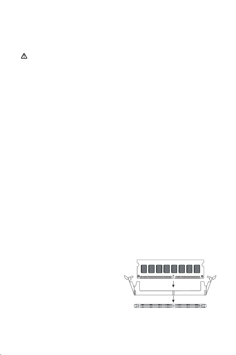
DIMM Installation Procedures
The DIMM slot has two keys marked
“VOLT” and “DRAM”, thus making the
module only fit in one direction. Note
that the module must be a 2.5V
unbuffered DIMM.
Step 1: Insert the module vertically into
the DIMM socket, and then
push it in.
Step 2: The plastic clip at the side of the DIMM socket will automatically close.

7
3.3 AGP Display Adapter Installation
The AGP slot on WinFast K7N415DA/420DA supports only 1.5V 4X AGP device.
To install an AGP display adapter, follow these steps:
Step 1: Push the clip at the end of AGP slot.
Step 2: Position the AGP card over the AGP slot. Do
not tilt the card. Insert the bus connector in the
slot and gently press the bus connector down.
Step 3: Push the clip back to close it.Step 1
Step 2 Step 3
3.4 Connecting Instructions
How each connector is connected and what it does is described here in detail.
See Chapter 2 to locate connectors.
Case Signal Connectors (FP1 & FP2)
FP1:
yPins [1 & 3] IDE-LED: IDE hard disk LED shows the
activity of a hard disk drive.
yPins [2 & 4] ACPI-LED: For ACPI LED connection
on the case.
yPins [5 & 7] RESET: Connects to the reset button
on the case. The reset button is used to “cold-boot”
the system without actually turning off the power,
reducing wear and tear on the power supply. Avoid
rebooting the system when the HDD LED is blinking.
yPins [6 & 8] PW_SW: Allows connecting to the
power button on the case.
FP2:
yPins [1 & 3] KEYLOCK: Keyboard lock switch lead. It connects to the
case-mounted keylock switch, allowing you to disable the keyboard function for
security purpose.
yPins [5 & 7 & 9] PW-LED: Power LED. Always lit when system power is on.
yPins [2 & 4 & 6 & 8] SPEAKER: Connects to the speaker on system’s case.

8
Hard Disk Connector
The on-board Enhanced IDE controller can support up to 4 IDE hard
drives or other ATAPI devices, such as CD-ROMs. This controller, as
with all Enhanced IDE controllers, consists of both Primary (IDE 1)
and Secondary (IDE 2) ports. Each port has an associated connector
and cable, which can support up to 2 ATAPI devices each.
All IDE devices have jumpers, which allow the user to configure the
device as either “Master” or “Slave”. A Master device is one that is
ALONE on the IDE cable, whereas a Slave device is installed as a
SECOND device on the same cable. Keep in mind that the Master
device will appear before the Slave device in the CMOS Setup, as
well as the
Operating
System
software. *Refer
to the device
documentation
for jumper
settings.
The Secondary
IDE port can be used for up to 2 additional ATAPI devices. Normally it’s
recommended that you connect your first hard drive to the Primary port, and the
first CD-ROM to the Secondary.
Make sure to align the RED stripe on the ribbon cable with Pin-1 on the
motherboard IDE connector. On most hard drives and CD-ROMs, the RED stripe
should be oriented towards the power connector of the device.
When using Ultra ATA 66/100 IDE cable (as shown above), the black color
connector on the cable is for Master drive, gray color is for Slave drive and blue
color is for connecting to IDE port onboard.
Floppy Disk Connector (FLP1)
The on-board floppy controller supports 2 floppy disk
drives. Make sure the RED stripe on the ribbon cable
is oriented towards Pin-1. Notice the “twist” between
the sets of connectors on the floppy cable. The
floppy drive “A” position is at the END of the cable,
whereas floppy drive “B” is hooked to one of the
connectors on the other side of the twist.
RJ45 Ethernet Connector and USB Connectors (UL1)
RJ45 LAN connector and two USB peripheral devices
connectors.
Blue
Connector
Gray
Connector
Black
Connector
Mainboard IDE Port
Slave Drive
Master Drive

9
Cooling Fans (FAN1, FAN2, FAN3)
CPU fan (FAN1), AGP fan (FAN2), and system fan
(FAN3) are small 3-pin Header Connectors that
provide 12-Volt power for CPU fan, power fan, and
system fan. Plug in the fan cable to the connector.
Stereo Audio/Video In Connectors
(J4, J5, J6)
J4 and J5 allows you to receive stereo
audio input from internal CD ROM
drives. J6 is for connecting other
auxiliary audio sources.
Power Supply Connector (PWR1)
This motherboard features an ATX-style Power Supply
Connector. This connector is keyed to prevent connection
in the wrong direction. Line up the locking mechanism on
the connector from the Power Supply with the tab on the
motherboard connector. Press down until the two
connectors are locked.
Serial, Parallel and VGA Ports
A 25-pin D-Sub
header is
provided on the
back panel for
a multi-mode
bi-directional
parallel port.
For
K7N415DA,
two 9-pin
D-Sub headers
are provided on the back panel for serial port COM1 and COM2. For K7N
420DA, there is one 9-pin D-Sub header for serial port COM1, as well as one
VGA port for monitor connection.
IrDA-Compliant Infrared Module Connector (IR1, CIR1)
The IrDA connector brackets hook directly to these
connectors on the motherboard. These connectors provide
support for the optional wireless transmitting and receiving
infrared module. CIR1 connector is for CIR; IR1 connector is
for IR.

10
Midi/Joystick, MIC, Line In, Line Out
yMidi/Joystick: Allow you to connect game joystick or
game pad for playing games or connect Midi devices for
playing or editing audio.
yMic: Allows microphones to be connected for inputting
sound.
yLine In: Allows tape players or other audio sources to be
recorded by your computer or played through the Line
Out.
yLine Out: Connected to headphones or speakers with amplifier.
PS/2 Keyboard and Mouse Connector (KYB1)
These two connectors are located on the back panel of the
motherboard.
USB Connectors (USB1 & USB2)
Each of these connectors is for connecting an optional USB
module to provide two additional USB connectors.
Audio Connector (JP4)
JP4 is for connecting to the sound module that comes with the package. See the
following figure for how to connect the sound module.
MIC
(Pink)
Line Out
(Lime)
Line In
(Light Blue)
Game Port
(Gold)

11
4. BIOS Setup
The BIOS Setup (also called CMOS Setup) is where many hardware
configurations are done and stored. This configuration information will remain in
the BIOS until it is changed, or cleared. CMOS refers to the chip in which the
BIOS information is stored, even when the power is turned off.
AwardBIOS CMOS setup utility allows you to change hardware settings in the
BIOS. This chapter gives a detailed description of each setup item as to what
function it controls and how one can modify its setting.
This motherboard also features a Flash BIOS. A Flash BIOS can be upgraded
by software programs.
The AwardBIOS is activated once you boot the computer. The BIOS reads
CMOS for system configuration information, and begins the process of checking
out the system and configuring it through the power-on self test (POST).
When three preliminaries are finished, the BIOS seeks an OS on one of the data
storage devices (hard drive, floppy disk, etc.) and launch it.
During POST, you can start the Setup program by pressing Del.
The AwardBIOS supports an override to CMOS settings, which will reset your
system to its default configuration if your computer can no longer boot up after
making changes.
We suggest you to only alter settings you have thorough knowledge of. Do not change
settings without a good reason.
To enter the Award BIOS program's main menu:
yTurn on or reboot the system.
yAfter the diagnostic checks, press the [Del] to enter the Award BIOS Setup
Utility.
To select items:
yUse the arrow keys to move between items and select fields.
yFrom the Main Menu, press arrow keys to enter the selected submenu.
To modify selected items:
yUse the [Up]/[Down] keys to modify values within the selected fields. Some
fields let you enter values directly.

12
4.1 Main Menu
Once you enter the AwardBIOS CMOS Setup Utility, the Main Menu appears on
the screen. Main Menu presents you the Setup functions included two exit
choices. You could use the arrow keys to select among the items and then press
Enter to the submenu.
* Description of selected item is shown in the column on the bottom of the screen.
4.2 Standard CMOS Features
The Standard CMOS Features allows you to choose the options in the setting
item for basic system configuration.
* The Item Help column contains the description of selected item.

13
Date [mm:dd:yy]
The BIOS determines the day of the week from the other date information. It is
for information only.
Time [hh:mm:ss]
The time format is <hour> <minute> <second>. The time is calculated based on
the 24-hour military-time clock. For example, 1 p.m. is 13:00:00.
IDE Primary Master/ Primary Slave/Secondary Master/Secondary Slave
After pressing [Enter], a menu window appears as shown on below:
The BIOS supports up to four IDE drives. This section does not show information
about other IDE devices, such as a CD-ROM and SCSI drives.
* The Item Help column contains the description of selected item.
IDE HDD Auto-Detection
The “IDE HDD Auto-Detection” utility is a very useful tool especially when you do
not know the type of hard disk you are using. You can use this utility to detect the
correct disk type installed in the system automatically. The BIOS will
automatically detect the hard disk size and model during POST.
The AwardBIOS supports 3 HDD modes: NORMAL,LBA and LARGE modes.
The Generic access mode, neither BIOS nor IDE controller, will make
transformations during accessing.
NOTE: There must be some software involved to support LBA or LARGE mode of
HDDs. All the software needed is located in the Award HDD Service Routine
(INT 13h). It may fail to access a HDD with LBA (LARGE) mode selected if
you are running under an Operating System, which replaces the whole INT
13h. UNIX operating system do not support either LBA or LARGE, and must
utilize the Standard mode. UNIX can support drives larger than 528MB.

14
Under the AUTO Mode, the BIOS can automatically detect the specifications and
optimal operating mode of almost all IDE drives. When you select type Auto for a
hard drive, the BIOS detects its specifications during POST, every time the
system boots.
IT IS RECOMMENDED THAT YOU SELECT THE TYPE AUTO FOR ALL DRIVES.
Drive A /Drive B [1.44M, 3.5 in.]
Select the correct specifications for the diskette drive(s) installed on your system.
Video [EGA/VGA]
Select the type of primary video subsystem on your system. The BIOS usually
detects the correct video type automatically, and supports a secondary video
subsystem that cannot be selected in Setup.
Halt On [All, But Keyboard]
During the power-on self test (POST), the system stops if the BIOS detects a
hardware error. You can ask the BIOS to ignore certain errors and continue the
process. There are the options:
All Errors: If the BIOS detects any non-fatal error, POST stops and
prompts you to take corrective action.
No Errors: POST does not stop for any error.
All, But Keyboard: POST does not stop for keyboard error, but stops for all
other errors.
All, But Diskette: POST does not stop for diskette drive errors, but stops for all
other errors.
All, But Disk/Key: POST does not stop for a keyboard or disk error, but stops
for all other errors.
Memory
You can not change the value in the Memory fields which are information only.
The setting item shows the total installed random access memory (RAM) and
amounts allocated to base memory, extended memory, and other (high) memory.
RAM is the computer’s working memory where the computer stores programs
and data currently being used, so they are accessible to CPU.
yBase Memory: Typically 640 KB is also called conventional memory. The
DOS operating system and conventional applications use
this area.
yExtended Memory: The memory over the 1MB boundary.
yTotal Memory: Total memory available from the system.

15
4.3 Advanced BIOS Features
* The Item Help column contains the description of selected item.
Virus Warning [Disabled]
The BIOS will halt on the system. Then the warning message appears as follows
if there is virus.
!PBVA WARNING!
Paragon Boot Virus analyzer has
detected virus activity on hard disk
We recommend you to press:
[Enter] Boot from clean disk
[C] Continue Boot
NOTE: When this item is enabled, the monitoring boot sector virus only happens
at the booting period. After you enter the system, this function is
disabled automatically. So you can run any kind of program, such as
many disk diagnostic programs, which attempt to access boot sectors or
the partition table of hard disk drive when it is running.
CPU Internal/External Cache
Cache memory is additional memory that is much faster than conventional
DRAM (system memory). When the CPU requests data, the system transfers the
requested data from the main DRAM into cache memory, for even faster access
by the CPU. Select Enabled to enable cache.
Quick Power On Self Test [Enabled]
Select Enabled to reduce the amount of time required to run the POST. A quick
POST skips certain steps. We recommend that you normally disable quick
POST. Better to find a problem during POST than lose data during your work.

16
First, Second, Third, Fourth Boot Device [HDD-0, Floppy, SCSI, Disabled]
Thiese setup fields determine which drive to be searched first, second or third for
the disk operating system (i.e. DOS). You can select your priority bootup drives
as Floppy drive A, IDE Hard Disk Drive C, D, E, F, or SCSI.
Swap Floppy Drive [Disabled]
This field is effective only in system with two floppy drives. This item allows you
to determine whether to enable the swap floppy drive or not (i.e. physical floppy
disk A assigned to logical drive B or physical drive B to logical drive A).
Boot Up Floppy Seek [Enabled]
During the “POST” process, BIOS will determine if the floppy disk drive installed
is 40 or 80 tracks. 360K-type is 40 tracks while 760K, 1.2M and 1.44M are all 80
tracks. Because few modern PCs have 40-track floppy drives, we recommend
that you set this field to Disabled to save time.
Boot Up NumLock Status [On]
This field allows you to determine the default state of the numeric keypad. “On”:
keypad is number keys after boot up. “Off”: keypad is arrow keys after boot up.
Gate A20 Option [Fast]
Gate A20 refers to the way the system addresses memory above 1MB (extended
memory). When set to Fast, the system chipset controls Gate A20. When set to
Normal, a pin in the keyboard controller controls Gate A20. Setting to Fast
improves system speed, particularly with OS/2 and Windows.
Typematic Rate Setting [Enabled]
Setting Enabled allows you to adjust both settings. You can use this feature to
accelerate cursor movement with the arrow keys. When this item is set Disabled,
keep holding down a key will let the system to use the default typematic rate
delay of 250 msec, and typematic rate of 6 chars/sec to input repeatedly.
Typematic Rate (Chars/Sec) [6]
When “Typematic Rate Setting” is Enabled, its selections allow you to select the
rate at which character repeats when you hold down a key.
Typematic Delay (Msec) [250]
When “Typematic Rate Setting” is Enabled, its selections allow you to select the
delay before key strokes begin to repeat.
Security Option [Setup]
If you have set a password at USER PASSWORD option in main menu, select
whether the password is required every time the System boots, or only when you
enter Setup. The options include: System and Setup.
APIC Mode [Enabled]
The options are: Enabled and Disabled.
OS Select For DRAM > 64MB [Non-OS2]
Allow you to access memory that is over 64MB in OS/2. Choose OS2 when you
are using OS2 and SDRAM size greater than 64 MB. Choose Non-OS2 for other
operating systems. The options are: Non-OS2, OS2.
Small Logo (EPA) Show [Enabled]
The options are: Enabled and Disabled.
This manual suits for next models
1
Table of contents
Other Leadtek Motherboard manuals