switches), so to allow safe inspection, detection of any faults, testing and maintenance operations.
Never disconnect a LEAF Microinverter M500-S or any part of the photovoltaic system without having previously exclu-
ded the AC distribution network.
Never disconnect the terminals from the PV panel during the operation of the LEAF Microinverter M500-S. To
disconnect a microinverter from the plant do the following:
• From the power distribution system, detach the section where there is the microinverter to disconnect
• Remove the PV connectors
• Remove the AC plug
All LEAF microinverters and the metallic elements of the system must always be connected to ground in accordance
with local and national electrical standards.
If the LEAF microinverter, or any accessory described herein, shows any of the following characteristics, remove it from
the plant following the instructions, and contact your distributor or installer:
• The power cables appear damaged.
• You suspect that liquid has penetrated into the product.
• The product was exposed to heavy rain or water.
• The product does not operate properly.
• The product has been dropped or has suffered any damage.
• There are noticeable signs of overheating.
The aluminum body of the LEAF Microinverter M500-S serves as a heatsink and can reach high temperatures, therefore
it should not be touched during operation.
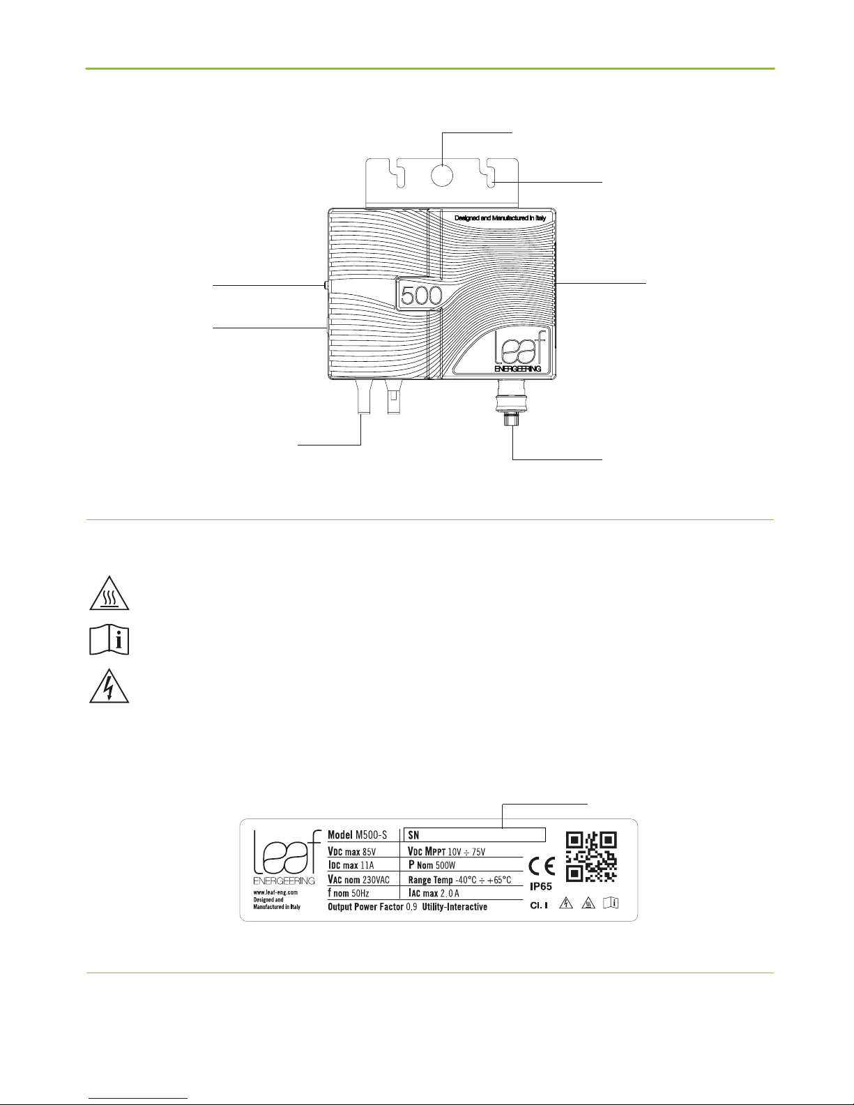
The proper functioning of the LEAF Microinverter M500-S is subject to the limits of voltage, current and power stated in
the product datasheet.
The metal case of the LEAF Microinverter M500-S does not require grounding.
Grounding is ensured by the dedicated conductor on the AC side, its connection should be performed based on natio-
nal laws for grounding wires
The use of the ground connection of the metal housing, when required by the rules of installation of the photovoltaic
system, must be carried out through the appropriate threaded socket marked with the grounding symbol and located
on one side of the enclosure.
Use the M5 screw supplied by the manufacturer, with a maximum length of 6 mm and with anti-loosening device
(washer) and using a yellow-green cable, with minimum section of 2.5 mm2, assembled with bushing.
The LEAF Microinverter M500-S does not incorporate devices to measure the insulation resistance between the DC
input and ground, consequently it must be installed in accordance to what is described in 5.3.2.11 of CEI EN 62109-2,
which indicates to consult local regulations to determine if additional functions are required or not.
Whenever the PV module is exposed to light, it provides a DC voltage: follow all warnings and safety instructions provi-
ded in the documentation of the module manufacturer.
Energy is supplied by all the active microinverters connected at the time.
The LEAF Microinverter M500-S contains no user-serviceable parts. In case of a repair, it should be returned to the
seller.
Do not connect the LEAF Microinverter M500-S to batteries.
In normal use, the container LEAF Microinverter M500-S can reach high temperatures: install in order to avoid any
contact, even accidental, with the unit.
All circuits branch must be able to carry a maximum current of 16A and must be provided with protection devices of
suitable size in accordance with the regulations in force in the place of installation.
Protection of the AC wiring
An additional protection of the AC wiring coming from the microinverter (which could include residual current devices,
earth leakage controllers and/or switches) must be provided, and may be required under existing national rules on
wiring.
In case of use of a protective device driven by residual current (RCD) or monitoring (RCM) for protection in case of
Before connecting the AC wiring of the photovoltaic system to the grid, local regulation conformity for electrical
systems must be checked carefully.
The AC cable must be connected to the distribution network through the protective equipment dened by local
regulations.
All the parts of the plant must be kept dry before and during installation and connection.
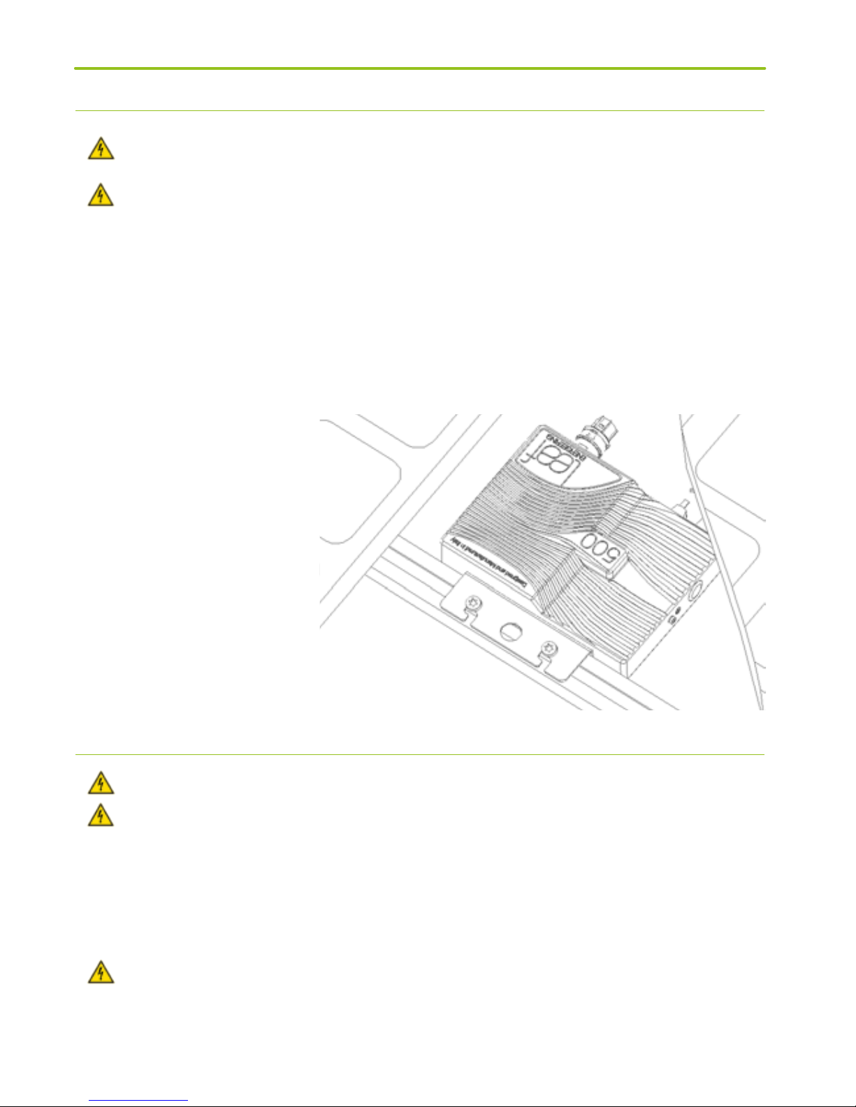
5. REMOVING A LEAF MICROINVERTER M500-S
• Isolate the AC bus of the photovoltaic system from the grid.
• Remove the AC cable from the LEAF M500-S microinverter to be removed
• If present, remove also the AC cable from the distribution unit and one of the supplied caps
• Remove the connectors from the photovoltaic panel to the LEAF M500-S microinverter
Strictly adhere to the connection sequence of LEAF M500-S microinverter, so to prevent parts accessible to the
operator from becoming live.