Tamarack Solar Ground Mount Kit User manual

2021 TAMARACK SOLAR - REVISION 5 FM SYSTEM MANUAL
1
Tamarack Solar
Ground Mount Kit
Installation Manual
Solar Products
Tamarack

2021 TAMARACK SOLAR - REVISION 5 FM SYSTEM MANUAL
2
Table of Contents
Features and Ratings. . . . . . . . . . . . . . . . . . . . . . . . . . . . . . . . . . . 3
Installer Responsibilities. . . . . . . . . . . . . . . . . . . . . . . . . . . . . . . . . 4
System Components . . . . . . . . . . . . . . . . . . . . . . . . . . . . . . . . . . . 5
Tools Required and Torque Specications . . . . . . . . . . . . . . . . . . . . . . . 6
Installation Preparation . . . . . . . . . . . . . . . . . . . . . . . . . . . . . . . . . 7
Vertical Post Spacing. . . . . . . . . . . . . . . . . . . . . . . . . . . . . . . . . . . 8
Foundation Design and Construction. . . . . . . . . . . . . . . . . . . . . . . . 9 - 15
Attaching Rails . . . . . . . . . . . . . . . . . . . . . . . . . . . . . . . . . . . . . .16
System Grounding . . . . . . . . . . . . . . . . . . . . . . . . . . . . . . . . . . . .17
Module Level Power Electronics (MLPE) Installation and Wire Management . . . . 18
Module Installation . . . . . . . . . . . . . . . . . . . . . . . . . . . . . . . . . 18 - 19
Module Compatability . . . . . . . . . . . . . . . . . . . . . . . . . . . . . . . 20 - 21
Limited Warranty . . . . . . . . . . . . . . . . . . . . . . . . . . . . . . . . . . . . .22
Customer Support
Tamarack Solar makes every eort to ensure your mounting kit is easy to install. If you
need assistance at any point in your installation or have suggestions on how we can
improve your experience, call customer support at 1-800-819-7236 ext 556 or email us at
support@tamaracksolar.com
Technical Support: 707-234-8107 or www.support@tamaracksolar.com

2021 TAMARACK SOLAR - REVISION 5 FM SYSTEM MANUAL
3
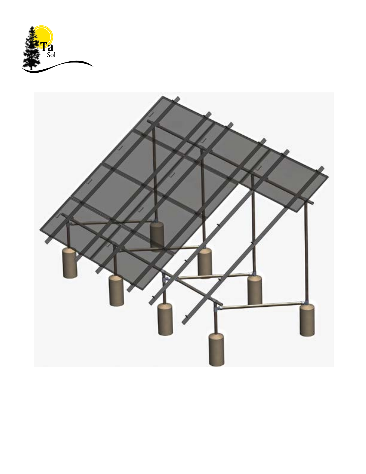
Tamarack Ground Mount System Features
• Designed for mounting photovoltaic (PV) arrays on the ground.
• Top clamps and rail attachments require the use of a single standard 1/2-inch socket
• 5050 Clamp for both mid-clamp and end-clamp use simplies ordering and stocking parts.
• Module clamps are spring loaded to ease module placement.
• Built-in wire management for module and microinverter cables
Tamarack Product Summary
The Tamarack Solar Ground Mount system is a visually appealing photovoltaic (PV) module installation system
that signicantly lowers PV module installation cost by allowing the installation professional to stock fewer
parts and to complete the installation in less time.
Certied to meet local and International Building Codes and ASCE/SEI-7
when installed in accordance with this manual.
ETL Listed to UL 2307 for bonding and grounding when in¬stalled in
accordance with this manual.
Rails, clamps, splices, and mounting devices are UL2703 Listed for
mounting at-plate Photovoltaic Modules and Panels
• Conforms to STD UL 2703 (2015) Standard for Safety First Edition: Mounting Systems, Mounting Devices,
Clamping/Retention Devices, and Ground Lugs for Use with Flat-Plate Photovoltaic Modules and Panels.
• Certied to CSA STD LTR AE-001-2012 Photovoltaic Module Racking Systems.
• Max Overcurrent Protective Device (OCPD) Rating: 20A
• Max Module Size: 25.6 ft²
• System Level Allowable Design Load Rating: meets minimum requirements of the standard (10 PSF down-
ward, 5 PSF upward, 5 PSF lateral). Actual system structural capacity is dened by PE stamped certication
letters.
Tamarack Solar Ground Mounts use Hollaender® structural aluminum pipe ttings that combined with pipe
make stable, secure, corrosion-free mounting rack systems for both ground and roof mounted solar arrays. Hol-
laender’s Speed-Rail® ttings are ideal for this application because the aluminum-magnesium 535 alloy used
to manufacture them is the most corrosion resistant aluminum alloy available. It can be used with steel without
any concern for galvanic corrosion. Hollaender Speed-Rail® ttings are now approved as UL 2703 Recognized
Components under ETL Mark 5006568. The system uses set-screws that penetrate the surface of the pipe to
ensure that ttings are electrically bonded to pipe and bracing, thereby eliminating the need for added bonding
components such as jumpers to provide a grounding path.
This manual describes proper installation procedures and provides necessary standards required for product
reliability. Warranty details are available on our website. www.tamaracksolar.com
All installers must thoroughly read this manual and have a clear understanding of the installation procedures
prior to installation. Failure to follow these guidelines may result in property damage, bodily injury or even
death.
5014275

2021 TAMARACK SOLAR - REVISION 5 FM SYSTEM MANUAL
4
Installer Responsibilities
• Follow all applicable local or national building and re codes, including any that may supersede this manual.
• Electrical installation should be conducted by a licensed and bonded electrician or solar contractor.
• Module maintenance or removal must not break the bonding path of the system.
• Ensure all products used are appropriate for the installation and array under the site’s wind and snow loading
conditions.
• Ensure information is used for the system design is accurate. Any inaccurate information used for the system
design will cause errors and are the installer’s responsibility to correct.
• We recommend consulting with your local building department about local regulations and building require-
ments, including soil conditions, terrain, and wind and snow load requirements. Local conditions and
• Use only Tamarack Solar Products parts or parts approved by Tamarack; substituting parts may void any
applicable warranty.
• Ensure bare copper grounding conductors do not contact aluminum and zinc-plated steel components in order
to prevent the risk of galvanic corrosion.
• The Installation should be inspected periodically, and any loose components or fasteners should be retight-
ened. Any corroded parts found should be examined carefully to assess whether the corrosion compromises the
physical integrity or performance of the system, and if so, the corrosion should be remediated, or the aected
components replaced.
• Provide an appropriate method of direct-to-earth grounding according to the latest edition of the National
Electrical Code, including NEC 250: Grounding and Bonding, NEC 690: Solar Photovoltaic Systems, and CSA
C22.1, Safety Standard for Electrical Installations, Canadian Electrical Code, Part 1
• Disconnect AC power before servicing or removing microinverters and power optimizers.
• Review photovoltaic module manufacturer’s documentation to ensure compatibility and compliance with
warranty terms and conditions.
• Maximum Series Fuse Rating for the photovoltaic array is 20 Amps.
For Technical Support, call 707-234-8107 or 800-819-7236 ext.556, email us at
support@tamaracksolar.com
Ground Mount Kit Description
• Kits contains all parts required except 2-inch schedule 40 pipe and concrete
• Choose one starter kit for rst column of 3 or 4 modules
• Expand with up to 7 add-on column kits
• Mount up to 64 modules on a single structure.
• Rated for up to 170 MPH wind speed and 50 psf of snow load
• Some situations require cross bracing (see table on page 8)

2021 TAMARACK SOLAR - REVISION 5 FM SYSTEM MANUAL
5
Tamarack Ground Mount System Components
3.1 inch Rail
Pipe Mount Clamp
Rail Splice
5050 Clamp
Ground Lug
Wire Management Clip
MLPE Adapter
Module Frame Ground Lug
Rail End Cap
Socket Tee Flexible Tee
Table of contents
Other Tamarack Solar Inverter manuals
Popular Inverter manuals by other brands

BARRON
BARRON EXITRONIX Tucson Micro Series installation instructions

Baumer
Baumer HUBNER TDP 0,2 Series Mounting and operating instructions

electroil
electroil ITTPD11W-RS-BC Operation and Maintenance Handbook

Silicon Solar
Silicon Solar TPS555-1230 instruction manual

Mission Critical
Mission Critical Xantrex Freedom SW-RVC owner's guide

HP
HP 3312A Operating and service manual