Asco Series 300 User manual

Operator’s Series 300
Manual Generator Paralleling System
Call 1 800 800-2726 (ASCO) for sales or service
Florham Park, NJ 07932-1591 USA
+Before reading please note the following
:
DANGER is used in this manual to warn of a
hazardous situation which, if not avoided,
will result in death or serious injury.
WARNING is used in this manual to warn of a
hazardous situation which, if not avoided,
could result in death or serious injury
.
CAUTION is used in this manual to warn of a
hazardous situation which, if not avoided,
could result in minor or moderate injury
.
Figure 1: (2)-Generator System
All service to this equipment should be provided
only by a qualified service technician. No work
should be attempted without complete
documentation, including but not limited to
drawings, manuals, and interconnect
information.
For service and support, call 800-800-ASCO (800
800 2726) or email customercare@asco.com
Rating Label
Each ASCO Series 300 Power Control System
(PCS) contains a rating label to define the loads
and withstand/closing ratings. Refer to the label
on the unit for specific values.
For a non-redundant system where the load
current is more than one generator’s full load
current and the generators are paralleled to
provide more power to the load, the main bus
current rating must be equal to or greater than the
sum of the two generator’s full load amps.
If the application is a redundant system where the
load current is equal to or less than the full load
amps of one generator and the generators are
being paralleled for redundancy, the rating must
be equal to or greater than the full load current of
the biggest generator. In addition, the output
circuit breaker must have proper overcurrent
protection, equal to or less than the main bus
rating label.
Do not exceed the values on the rating label.
Exceeding the rating can cause personal injury
and/or serious equipment damage.
381333-453

ASCO Series 300 Operator’s Manual
Page 2 ASCO Power Technologies 381333-453
TABLE OF CONTENTS
RATING LABEL..................................................................................................................................................1
ASCO SERIES 300 PRODUCT,AUTOMATIC CONTROL SYSTEM............................................................................3
INSTALLATION.......................................................................................................................................................... 4
SUPPORTING FOUNDATION,MOUNTING,LINE CONNECTIONS,TESTING POWER CONDUCTORS,
CONNECTING POWER CABLES,GENERATOR CIRCUIT BREAKER CONTROL CIRCUITS,
GROUNDING DIFFERENT GENERATOR DC CONTROLS ........................................................................................4
MANUAL MAINTENANCE OPERATION ...................................................................................................... 5-6
OPERATING MODE(S)........................................................................................................................................ 7-8
EMERGENCY MODE ..........................................................................................................................................7
BLOCK LOAD CONTROL ....................................................................................................................................8
FEATURES ............................................................................................................................................................ 9-11
BUS OPTIMIZATION ...........................................................................................................................................9
LOAD DEMAND .........................................................................................................................................10-11
TEST FACILITIES:SINGLE ENGINE TEST...........................................................................................................11
OPERATOR CONTROLS ...............................................................................................................................12-14
A. MASTER CONTROL STATION,B. GENERATOR CONTROL STATION ................................................................12
GENERATOR CONTROL STATION (FIGURE 5), ENGINE/GENERATOR CONTROL SWITCH,
SYNCHRONIZING MODE SWITCH (SMS), ENGINE MALFUNCTION INDICATION ,
EMERGENCY STOP ...................................................................................................................................13-14
MASTER CONTROL STATION (FIGURE 4), BUS ALARM RESET,ALARM SILENCE,
PRIORITY #LOAD SHED BYPASS/RESET (VIA OIT), LOAD DEMAND MODE (VIA OIT),
BUS OPTIMIZATION,(VIA OIT), MANUALLY INITIATED PARALLEL (VIA OIT) .........................................................14
OPERATOR INTERFACE TERMINAL (OIT)............................................................................................15-17
FACTORY DEFAULT SETTINGS ................................................................................................................18-19
INDEX ..........................................................................................................................................................................20

Operator’s Manual ASCO Series 300
381333-453 ASCO Power Technologies Page 3
ASCO Series 300 Product
The ASCO Series 300 PCS is an affordable and
feature-rich product for paralleling generators and
controlling loads. The ASCO Series 300 PCS control
system is an integrated platform that provides
sequencing, synchronizing, generator load sharing,
protective functions, power management, and many
other industry-leading features, all while minimizing
costs.
The ASCO Series 300 PCS utilizes the ASCO Power
Technologies industry-leading and time-proven dual-
contactor based Closed Transition Transfer Switching
(CTTS) mechanism to parallel two generators per
CTTS unit. A two generator system (refer to Figure 2)
consists of a single section, while a three and four
generator system consists of two sections. An
accessory can be added at the time of ordering of the
two generator system for future expansion.
Automatic Control System
The ASCO Series 300 PCS is an automatic control
system that may start and/or stop generators and
operate the unit at any time to maintain power to the
load.
NOTICE
System startup by ASCO Power Technologies is
recommended. An experienced electrician must install
the system.
Figure 2: (2)-Generator System

Operator’s Manual ASCO Series 300
381333-453 ASCO Power Technologies Page 4
Installation
The system is factory wired and tested. Installation
requires mounting, connecting service cables, and
connecting generator control and generator circuit
breaker control circuits.
Supporting Foundation
The supporting foundation for the enclosure must be
level and straight. Refer to the applicable enclosure
outline drawing included with the system for all
mounting details including door opening space.
If bottom cable entry is used, the foundation must be
prepared so that the conduit stubs are located
correctly. Refer to the enclosure outline drawing for
specified area and location. Provide cable bending
space per UL, NEC and local code requirements.
Mounting
Refer to the outline and mounting diagram and
mount the enclosure according to details and
instructions shown on the diagram.
Protect the equipment from construction debris and
metal chips to prevent malfunction or shortened life.
Line Connections
Refer to the wiring diagram provided with the
equipment. All wiring must be made in accordance
with all applicable codes.
De-energize the conductors before making any line
or auxiliary circuit connections. Be sure that the line
connections for all generators are in proper phase
rotation. Lockout and tag all power sources before
working on unit. Make sure engine generators are
not in operation.
Testing Power Conductors
Do not connect the power conductors to the
equipment until they are tested. Installing power
cables in conduit, cable troughs, and ceiling-
suspended hangers often requires considerable force
to maneuver. The pulling of cables can damage
insulation and stretch or break the conductor’s
strands. For this reason, after the cables are pulled
into position, and before they are connected, they
should be tested to verify that they are not defective
or have been damaged during installation.
Connecting Power Cables
After the power cables have been tested, connect
them to the appropriate terminal lugs (if provided)
on the equipment as shown on the wiring diagram.
Make sure that the cables being installed are suitable
for use with the lugs.
Generator Circuit Breaker Control Circuits
The generator circuit breaker control connections
are located on customer terminal block. Connect
signal wires to appropriate terminals as specified on
the wiring diagram and interconnect spreadsheet.
Generator Circuit Breaker
The required generator circuit breaker (not included
with the ASCO Series 300 System) provides the
overcurrent (short circuit) protection for the system.
The generator circuit breaker must have DC shunt
trip provisions and auxiliary contacts for ASCO use.
The control system has a dry contact (rated at 10A,
30VDC or 10A, 240VAC, tripping duty) available
for shunt tripping the generator circuit breaker. This
contact must be connected during installation.
The ASCO Series 300 controller needs to monitor
the position of the generator circuit breakers via an
auxiliary contact. Refer to the drawings and the
interconnect spreadsheet for further information. If
a generator circuit breaker is open, the ASCO Series
300 will consider the generator unavailable and will
send a shutdown signal.
If the generator circuit breaker opens for any reason,
the ASCO Series 300 contactors will open if AC
control power is available from any remaining
generator connected to the bus. If no AC power is
available, the contactors must be opened manually.
The control system will alarm and not be available
until the generator circuit breaker is closed again
and the alarm is reset.
Grounding Different
Generator DC Controls
24 VDC control power is required for this system.
Generator batteries should be 24 VDC and
negatively grounded. Optional DC to DC isolators
can be added to the DC Control Power circuit to
prevent circulating currents and/or unintentional
grounds. If the generator grounding systems are not
negatively grounded or unknown, the optional
isolators are required.

Operator’s Manual ASCO Series 300
381333-453 ASCO Power Technologies Page 5
Manual Maintenance Operation
Proper precautions must be taken, including
Lock Out/Tag Out procedures, to ensure
personal safety. Do not manually operate the
contacts without de-energizing sources properly,
including locking out and tagging every source.
A maintenance handle is provided on the CTTS
contactor assembly for maintenance purposes only.
Manual operation of the contactors should be
checked before it is energized (before it is operated
electrically) by a qualified technician.
Do not manually operate the unit until all power
sources are disconnected: open both generator
circuit breakers and all load circuit breakers.
Figure 3a. J-design Transfer Switch
Maintenance Handle Operation.
1. After de-energizing both power sources, open
the enclosure door. Locate and remove the
maintenance handle. Select J-design, H-design
or G-design. See Figures 3a, 3b and 3c.
J-design (Figure 3a) and H-design (Figure 3b)
The maintenance handle is stored in clips on
the left side of the transfer mechanism
assembly.
G-design (Figure 3c)
The maintenance handle, hub, and pin are
stored on the center frame of the transfer
mechanism assembly.
2. Install the handle into the hole in the molded
hub. Move the handle up or down as shown to
manually operate the transfer switch to close
and reopen the contacts. It should operate
smoothly without any binding. If it does not,
check for shipping damage or construction
debris.
J-design (Figure 3a) and H-design (Figure 3b)
The transfer switch has two contact shaft hubs.
Install the maintenance handle into the hole in
the molded hub. The upper hub operates the
Generator 2 contacts. The lower hub operates
the Generator 1 contacts.
G-design (Figure 3c).
Install the hub (with pin) onto the shaft. Insert
the maintenance handle into the side hole in the
hub. Push in the shaft to operate the Generator
1 contacts. Pull out the shaft to operate the
Generator 2 contacts.
3. After checking manual operation, return all
transfer switch contacts to the open position.
Generator 1 and Generator 2 contacts must be
open. Check contact position indicators.
4. Remove the maintenance handle and store it on
the transfer switch in the place provided.
J-design (Figure 3a) and H-design (Figure 3b)
Store the maintenance handle in the clips on
the left side of the transfer.
G-design (Figure 3c).
Store the maintenance handle, hub, and pin on
the center frame of the transfer.
Note: If Generator 1 and Generator 2 connections
are reversed this operation is also reversed.
Verify that the maintenance handle has been stored
properly before electrically operating the transfer
switch.
Left side of the
transfer switch
Hubs shown with
Generator 1 source
contacts open and
Generator 2 source
contacts closed.
Maintenance handle
Generator 2
contact shaft hub
Generator 1
contact shaft hub
Clip

ASCO Series 300 Operator’s Manual
Page 6 ASCO Power Technologies 381333-453
Figure 3b. H-design Transfer Switch Maintenance Handle Operation.
Figure 3c. G-design Transfer Switch Maintenance Handle Operation.
window
indicators
OPEN or
CLOSED
Generator 2
contacts
Generator 1
contacts
contact position
indicators (left side)
With all power OFF,
grasp handle firmly
with both hands.
Slide the hub onto the
shaft and insert the pin.
Turn counterclockwise
to OPEN contacts.
Turn clockwise to
CLOSE contacts.
Insert handle
into hole
(spring fully
compressed
counterclockwise DOWN
OPENS the contacts
Pull out shaft (upper) to open Gen.
2 source contacts (upper).
Push in shaft (upper) to open Gen.
1 source contacts (lower).
clockwise DOWN CLOSES the contacts
Pull out shaft (upper) to close Gen. 2
source contacts (upper).
Push in shaft (upper) to close Gen. 1
LOWER SHAFT
Generator 1 contacts
UP closes the contacts
DOWN opens the contacts
UPPER SHAFT
Generator 2 contacts
UP opens the contacts
DOWN closes the contacts
Left side of the
transfer switch
Maintenance
handle
clips
Generator 2
contact shaft hub
Generator 1
contact shaft hub
Window indicators
Ois o
p
en
,
Cis closed
Contact position
indicators
(right side)
Generator 2
contacts
Generator 1
contacts
Hubs shown with
Generator 1 source
contacts open and
Generator 2 source
contacts closed.

Operator’s Manual ASCO Series 300
381333-453 ASCO Power Technologies Page 7
Operating Mode(s)
This ASCO Series 300 PCS is designed to start up
to 4 engine-generator sets upon receipt of a signal
that emergency power is required from any of the
automatic transfer switches (ATS).
Emergency Mode
Whenever the individual engine generator control
switches are placed in their automatic position, the
engine generator system is on standby in readiness
for automatic starting and synchronization in the
event of a power failure signal.
In the event of a power failure, all generator(s)
automatically start and come up to speed. The first
generator set to achieve 90% of nominal voltage
and frequency shall be connected to the bus.
Electronic interlocks permit the connection of only
one engine generator to the dead generator bus in
the event of simultaneous generator relay
operation. Upon sensing the availability of
emergency power, the priority-1 load block will be
able to transfer to the emergency bus. Priority 1
loads cannot be shed from the emergency bus and
are always allowed to transfer.
(Note: If priority 1 loads are not calling for an
engine start because they have not lost normal
power, a priority-pass along feature will be
activated.
Generally, if no loads in any priority block are
calling for an engine start, all loads in lower
priority blocks will be shifted up to a higher
priority for block load add/shed purposes.)
The synchronizer will automatically adjust the
frequency of the on-coming generator to
synchronize with the bus. When synchronism is
achieved, the on-coming generator is paralleled to
the bus. When the second generator’s paralleling
contactor is closed the priority-2 load block will be
allowed to transfer their loads to the emergency
bus. As each generator parallels to the bus, another
block of load is allowed to add, until all generators
and all loads are online.
Upon sensing that normal utility power has been
restored to acceptable limits, a sequence shall
begin to transfer the load back to the utility source.
The re-transfer shall be initiated after the retransfer
to utility time delay has expired (adjustable at each
ATS from 0 minute to 30 minutes) allowing an
open transition transfer return to utility. After all
the transfer switches have re-transferred their loads
to the normal source, the generator circuit
paralleling contactors are simultaneously opened
and the engine generators run for an adjustable no-
load cool-down period (adjustable at the local
generator controls if provided by the generator
controller manufacturer). The controls are
released and the generators placed in readiness for
the next power failure.

ASCO Series 300 Operator’s Manual
Page 8 ASCO Power Technologies 381333-453
Block Load Control
Each load (except priority 1) has an estimated KW
value and step time delay associated with it. As
each block of load is allowed to transfer to
emergency power, the individual loads will begin
their step time delay. As the time delay for each
load completes, the load will receive a permissive
signal to transfer to emergency power. If no delay
is desired, the individual step times can be set to
zero seconds, and the loads will transfer
immediately when the load block is permitted to
transfer to emergency.
Note: Any automatic transfer switch without the
30B accessory (Load Shed) will automatically
transfer to emergency on its own regardless of the
permissive signal. Priority 1 loads must not have a
30B accessory.
If a generator fails while operating in the automatic
mode, it is disconnected from the bus and
shutdown. Audible and visual alarms will be
activated to indicate the condition. System loads
will not shed unless a bus overload or a bus under
frequency occurs. This feature is referred to as
“Load-Latch”.
A soft push-button on the operator interface
terminal (OIT) permits override of the load-shed
circuits for supervised operation (one for each
priority except priority 1) refer to (Figure 9).
Loads that have been block shed can be manually
re-added using the priority-# Load Shed
Bypass/Reset push-button located on the Master
control section OIT. By pressing the Load Shed
Bypass/Reset push-button, the system will transfer
the selected load block to the emergency bus. By
pressing the Load Shed Bypass/Reset push-button
a second time, the ENTIRE selected load block
will shed. The OIT System Status screen will
annunciate the status of each Priority load block,
indicating if it is shed or manually bypassed. Refer
to (Figure 8). If the operator inadvertently
bypasses the load shed and overloads the
Generator(s) resulting in a bus under-frequency, all
manually bypassed loads will be automatically
shed along with blocks of load such that the
remaining load blocks shall be one less than the
number of generators remaining on the bus. The
“Bus Under Frequency” annunciator light will
indicate this condition.
If the online load exceeds 105% of rated generator
capacity, unsupported load blocks (load block
priorities greater than the number of generators
online) will be step shed in reverse priority at one
second intervals. No load blocks equal to or less
than the number of generators online will be shed.
(Ex. If you have two generators online, load blocks
1 and 2 will stay online, priority 3 and above will
be shed). The Bus Overload light will light to
indicate that the bus is overloaded automatically
reset as the overload is corrected. When the online
load no longer exceeds 105% of the generator
capacity, step shedding will cease, and the system
will continue to power the loads that are left
online. Indicating lights will annunciate the status
of each Priority load block, indicating if any loads
in that block are shed or if the load block is
manually bypassed. If the operator bypasses the
load shed to bring those shed loads back online,
and the online load exceeds 105% of capacity
again, the system will again step shed loads in
reverse priority until the load no longer exceeds
105% of capacity.
Note: Block loading can be disabled so all loads
(except priority 1) can be added to the emergency
bus only through the bus optimization feature.

Operator’s Manual ASCO Series 300
381333-453 ASCO Power Technologies Page 9
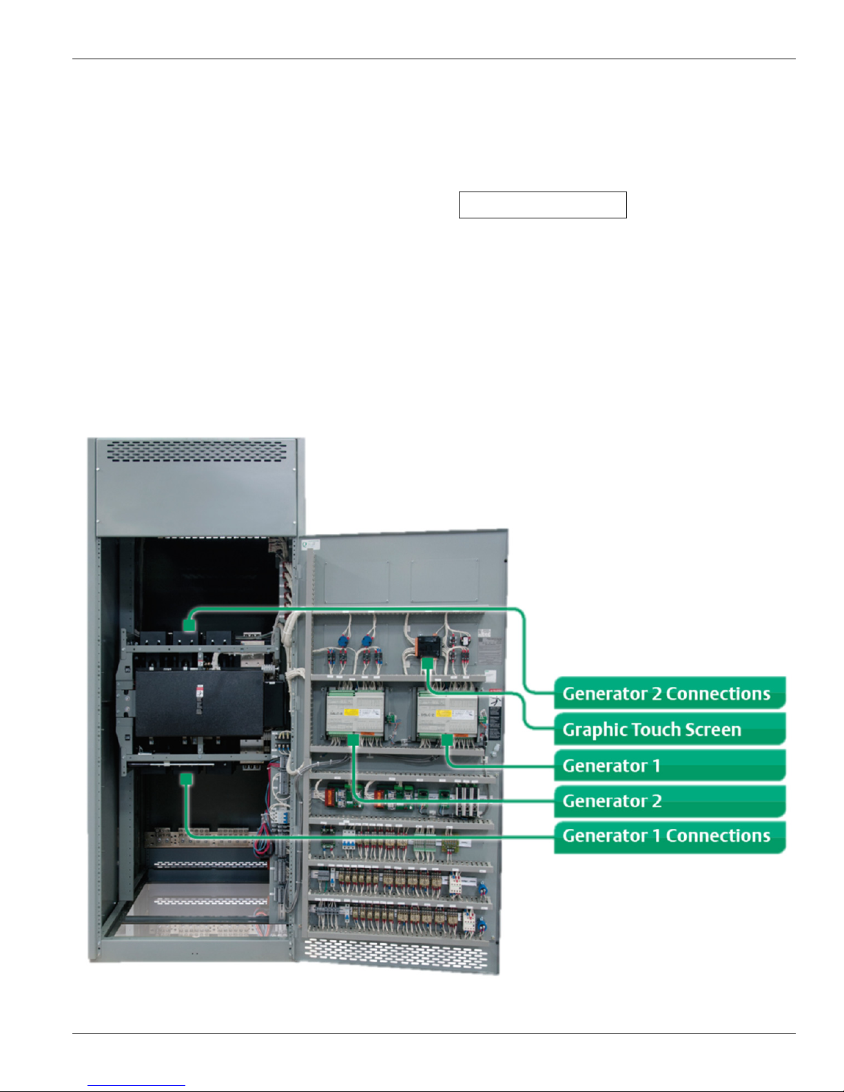
Features
Bus Optimization
Each load priority is determined by which load
block wiring an ATS is connected to. Priority
wiring is included for priorities 1 to 4 (2-gen
system) or priorities 1 to 8 (3- and 4-gen systems).
To change a priority, an ATS engine start signal
and load shed signal need to be moved to a
different priority block wiring.
Should a Priority Block fail to be added to the bus
while operating in the Emergency Mode, loads
may be added manually by the operator as
described in Block Load Control or automatically
through "Bus Optimization". Bus Optimization is
provided to re-add shed loads one block at a time
based on predetermined kW loading values up
95% (adjustable via OIT) of the capacity of the on-
line power. This percentage value is referred to as
the Bus Optimization KW de-rating value.
With the Bus Optimization switch in the "on"
position during emergency mode and with loads
shed (loads requiring power but are not connected
to the emergency bus), after a stabilization time
delay (Bus Opt stable delay) the optimization
feature is activated and a Bus Optimize Active
light illuminates. The Bus Optimize Active light
flashes through the duration of the stabilization
time delay (default 30 seconds, adjustable via
OIT). At this time, the Bus Optimization loading
control will determine if there is enough room to
add the next load block by checking the pre-set
Load Value (field adjustable, accessible via the
OIT) assigned to the highest priority block that is
shed and compare it to the excess generator bus
capacity (also known as Headroom).
If it is determined that the load can be added
without exceeding the Bus Optimization KW de-
rating value, the load is signaled to add. The real
time kW output of the generator bus is constantly
measured and the next load block priority is
evaluated. Loads are evaluated at a preset time
interval defined via the OIT (Bus Opt Step Time).
When the bus has been loaded to a level such that
the next load would exceed the de-rating value, the
Next Load Exceeds Headroom light (on OIT) will
activate and load adding will pause. The system
will continuously monitor the generator load and
evaluate if the next load step can fit on the bus. If
building load decreases and the next load can fit
(for the duration of the step time delay), the system
will add it and continue the evaluation process
until as many loads as possible are added to the
bus. Refer to (Figure 11).
If the load has already been added, there is no
reason to compare it to see if it will fit; the
program will skip to the next available load.
If the load is not calling for an engine start (load
still fed from normal power), it will be skipped.
If at any time, the online load exceeds 105% of
available rated capacity, the system will remove
the last load block that was added. If the online
load does not decrease to less than 105% of rated
capacity, load blocks will be shed one at a time,
every second in reverse order until the overload is
corrected or until the number of load blocks online
equals the number of generators online. Load
blocks with associated generators online will not
be shed. The Bus Overload light will light to
indicate that the bus is overloaded automatically
reset as the overload is corrected. In this event, the
system will begin a 30 second overload
stabilization delay time (fixed) before evaluating
additional load to be added to the bus.
If a generator fails, it will be removed from the
bus. If the remaining loads online exceed 105% of
the remaining online generator capacity, the load
blocks will step shed as described in the previous
paragraph. If the load does not exceed the online
capacity, no loads will shed. The Bus Overload
light will light to indicate that the bus is
overloaded automatically reset as the overload is
corrected.

ASCO Series 300 Operator’s Manual
Page 10 ASCO Power Technologies 381333-453
In the event of a bus Under-frequency, all
optimized load blocks will be shed as well as any
additional unsupported blocks of load. Load
blocks will be shed such that the remaining load
blocks shall be one less than the number of
generators remaining on the bus. The “Bus Under
Frequency” annunciator light will indicate this
condition. Refer to (Figure 4).
No loads can be manually added while a bus under
frequency alarm indication is active. The operator
must acknowledge the alarm by pressing the
Alarm Reset pushbutton via the OIT (provided bus
under frequency is still not active). After the
operator acknowledges the alarm, the system will
again be block loaded. Each priority block for
which there is a generator online will be added to
the system, one load block per generator online.
While the load block is adding to the bus, if bus
optimization is enabled, the bus optimization will
start adding loads after a bus optimization start
time delay and in the same manner as described
previously for bus optimization in the preceding
paragraphs.
If a load block is manually bypassed, it will add
subject to its individual step timer. If a load block
was already optimized on, it will remain on. If the
load block is then manually shed, it will shed
immediately. Only load blocks in excess of the
number of generators can be shed manually.
Once a priority load block has been added
to the bus, the LOAD SHED light in OIT
for the associated priority will turn off.
Refer to (Figure 8).
Load Demand
The Load Demand logic controls the number of
generating sets to remove excess generator
capacity and add additional capacity when needed,
thus keeping the optimum number of generators
online at all times. Generator load demand saves
fuel and wear by running fewer generators at a
more efficient load level.
Entering Load Demand Mode
After all generators sets have been paralleled to the
bus and all loads connected that require power, a
stabilization time delay (0-300 seconds) factory
sets at 30 seconds will be initiated while a Load
Demand Mode light (in OIT) flashes. At the
expiration of the time delay period, the system will
operate in load demand mode at which time the
mode light remains illuminated.
Removal of Generator Sets from the Bus
The number of generators a system requires at any
time is defined as N. Load demand seeks to
remove the lowest priority generators (priority
value set at OIT) that are in excess of N. When the
system is operating with more generators online
than the system needs and the system load falls
below the drop out load value (default setting of
80% KW rating of N generators) a 20 second time
delay (field adjustable from 0 - 300 seconds) is
initiated and a “Gen Stop TD Active” light start
flashing. If the load stays below the dropout value
for the duration of the time delay, the generator(s)
with the lowest priority that are excess capacity
will be taken offline. The engine(s) will run for
their cool down period (based on the local genset
controls), then shutdown.
Determining Dropout Value
(KW Capacity of Online Generators – KW
Capacity Value of Lowest Priority Generator
Online) x (Drop out %)
If while operating in the load demand mode, an
engine-generator set malfunction occurs and the
generator goes offline, Load Demand mode will
momentarily reset and all remaining generators
will be brought online.
If the online load exceeds 105%, load demand will
be canceled and all generators will be started, load
blocks not equal to the number of generators
online will be step shed based on priority, one
every second, until the system load falls to not
more than 105%.

Operator’s Manual ASCO Series 300
381333-453 ASCO Power Technologies Page 11
Addition of Generator Sets to the Bus
If the bus kW (system load), is equal to or greater
than the generator load demand pickup value for
the duration of the load demand start td (default 5
seconds), the controls will initiate the starting and
paralleling of the next set in sequence. If, during
the time delay period, the online load exceeds
105% of the online generator capacity (signifying
bus overload), the time delay will be bypassed and
all generators will be immediately started and
paralleled (load demand canceled). Any loads
blocks not equal to the number of generators
online will be shed. If the online load exceeds
105%, load blocks not equal to the number of
generators online will be step shed based on
priority, one every second, until the system load
falls to not more than 105%.
Note:Load priorities can be manually entered or
automatically set by the system based on generator
run-time values. The auto-gen priority feature can
be disabled or enabled. If enabled, the run-time
hours must be manually retrieved by an operator
from the gen-set controls and programmed into the
OIT screen. Once set, the system will add to the
run-time hours when the generators are run. Refer
to Figure 4 for the Master Control Station layout,
including the OIT screen.
Test Facilities: Single Engine Test
Each engine can be started for test purposes by
placing its generator control switch to the off-line
position. In this mode, the generator circuit
paralleling contactor will remain open. Should a
normal source outage occur during this mode of
operation, the paralleling contactor will close and
the remaining units will be started. Upon
restoration of normal power, the system will revert
to single engine test mode until the switch is
returned to the AUTOMATIC position. For on-
line test, placing of the generator control switch to
the on-line position will present a similar operation
except that the generator paralleling contactor will
close when the generator achieves nominal voltage
and frequency. Refer to (Figure 5) for the
Generator Control Station layout.

ASCO Series 300 Operator’s Manual
Page 12 ASCO Power Technologies 381333-453
Operator Controls
A. Master Control Station
Figure 4 – Master Control Station
B. Generator Control Station
Figure 5 – Generator Control Station (Shown Typical for Gen 1 & 2)

Operator’s Manual ASCO Series 300
381333-453 ASCO Power Technologies Page 13
Generator Control Station (Figure 5)
An Engine/Generator can be manually started and
stopped via the Engine/Generator Control
Switch and Synchronizing Mode Switch.
The control switch functions are as follows:
Engine/Generator Control Switch
LOCKOUT/RESET - When placed in this
position, the Engine Generator set is locked out
from start operation. If the Engine Generator set
was shut down due to an Engine malfunction, the
shutdown malfunction will be reset. If the Engine
is running when the switch is moved to this
position, it shall be immediately shut down
without a cool down period. If the Generator
circuit paralleling contactor was closed, it will
immediately be tripped open.
OFF/COOLDOWN - If the Engine Generator is
running and output circuit paralleling contactor is
closed, when the switch is placed in this position
the circuit paralleling contactor will immediately
trip open and the Engine Generator set shall run
for a cool down period as set at the gen-set
controls. If the Engine is running and the output
circuit paralleling contactor is not closed, when the
switch is placed in this position, the cool down
timer is bypassed and the Engine is turned off
immediately. If the Generator controls are already
receiving an automatic start signal from the Master
Controls or subsequently receive an automatic start
signal, an alarm will sound and the Generator is
considered to be shut down and locked out. An
Engine Generator set cannot be started when the
switch is in this position.
AUTOMATIC - With the switch in this position,
the Engine Generator set controls shall be in the
readiness for automatic operation upon receipt of
an Automatic start signal from the master controls.
The Engine Generator will start and run, and the
Generator circuit paralleling contactor will be
closed to the Generator Paralleling Bus. When an
Automatic start signal from the master controls is
removed, the Generator circuit paralleling
contactor will be tripped open and the Engine
Generator will run for cool down period.
TEST OFF-LINE - With the switch placed in this
position, the Engine Generator set shall
immediately start and run. In this mode, the
Generator circuit paralleling contactor will remain
open and shall not be connected to the Generator
Paralleling Bus unless an Automatic start signal is
received from the master controls. If an Automatic
start signal is received, automatic operation will be
initiated as described in "Automatic". If the
Automatic start signal is removed, the Generator
circuit paralleling contactor will be tripped open
but the Engine Generator will continue to run as
long as Test Off-Line is selected.
TEST ON-LINE - When placed in this position,
the Engine Generator set shall immediately start,
run and close the Generator circuit paralleling
contactor to a de-energized Generator Paralleling
Bus or synchronize to and close to an energized
bus according to the selected synchronizing mode.
If an Automatic start signal is received, the
Generator circuit paralleling contactor will remain
closed. If the Automatic start signal is removed,
the Generator circuit paralleling contactor will
remain closed and the Engine will continue to run
as long as Test On-Line is selected.
Synchronizing Mode Switch (SMS)
ON - With the switch in this position the
Automatic Synchronizer is fully automatic and
will send Raise/Lower speed signals to the
governor to control the Generators frequency, or
synchronize, with the energized Bus. When the
phase differential is less than ±5 electrical degrees,
the synchronizer will initiate a signal to the
controls to close the Generator circuit paralleling
contactor.
OFF - With the switch in this position, the
Automatic Synchronizer is turned off. The
Automatic Synchronizer should be turned to OFF
while attempting to manually parallel the
Generator to an energized Bus.

ASCO Series 300 Operator’s Manual
Page 14 ASCO Power Technologies 381333-453
Engine Malfunction Indication
Upon initiation of a malfunction, the generator set
will be removed from the bus and shutdown.
Shutdown and lockout conditions are annunciated
by a Common Shutdown indication.
Audible and visual alarm signals are activated for
Common Alarm and Common Shutdown.
Alarms need to be reset by pressing the alarm reset
push button on the generator control station.
Shutdowns are reset by placing the
Engine/Generator Control Switch to the
lockout/reset position. Refer to (Figure 5).
An audible alarm silence circuit is provided. The
audible alarm silence is reset upon reset of the
malfunction or upon the occurrence of a
malfunction after the alarm has been silenced. The
audible alarm will annunciate each malfunction
and pre-alarm.
Emergency Stop
Upon initiation this will open the generator source
and shutdown the affected generator. The
emergency stop button must be reset and the
generator control switch must be taken to
lockout/reset then back to automatic to have the
system back to a readiness state.
Master Control Station (Figure 4)
Alarm Silence
This button will light red when an audible alarm
horn is sounding. Pushing and releasing the button
will silence an audible alarm horn. When
depressed, this button also serves as an alarm horn
test circuit.
Bus Alarm Reset (via OIT)
The bus alarm reset push button is used to reset
non-active systems alarms such as bus under
frequency, bus over frequency, bus under voltage,
and bus over voltage.
Priority # Load Shed Bypass/Reset (via OIT)
The priority load shed bypass/reset button is used
to add or shed load that is in addition to the load
blocks that can currently be supported by the
system (1 load block per generator online). If only
a single generator were to come online, pressing
this button (for priority 2) will allow the priority 2
load block to be added to the bus. Pressing this
button (for priority 2) again will shed the priority 2
load block. Priority buttons are also available for
priority 3 and 4. If the system includes the gen 3-4
design, then priority buttons 5-8 will also be
available. Refer to (Figure 9).
Load Demand Mode (via OIT)
This switch will enable/disable/reset load demand
functionality. If in load demand mode, if load
demand is disabled or reset, all previously
shutdown generators will parallel again to the bus.
Refer to (Figure 9).
Bus Optimization (via OIT)
This switch will enable/disable bus optimization
mode. Refer to (Figure 9 & 11).
Manually Initiated Parallel (via OIT)
The system includes a Manually Initiated
Paralleling feature. Refer to (Figure 12).
Set the Sync mode switch on the door to ON.
From the OIT, go to the manually initiated parallel
screen. If the generator is selected to manually
initiated parallel, the Automatic Synchronizer will
send Raise/Lower speed signals to the governor to
control the Generators frequency which will match
frequency, or synchronize, with the energized Bus.
The Generator will hold synchronism, or phase
lock, with the Bus but will not issue a signal to the
controls to close the Generator circuit paralleling
contactor. The operator can then select the “close
circuit paralleling contactor” button to issue a
close command to the Generator circuit paralleling
contactor if the generator is in sync with the bus.
This mode can be used for calibration and
troubleshooting of the Synchronizer and Speed
Control system.

Operator’s Manual ASCO Series 300
381333-453 ASCO Power Technologies Page 15
Operator Interface Terminal (OIT)
An OIT operator interface terminal is accessible
via the master control section door. This operator
interface allows for priority settings, time delay
settings and system monitoring features.
User settings may be modified by selecting the
MENU button on any screen. Once in the menu
screen, you have to use the up and down arrows to
select Login/Logout and hit the enter button. At
the login screen, select the enter password prompt.
Enter your password [default is 2726]. Select the
login button. The banner will indicate if the user is
Logged In or Logged Out. Passwords can be
changed after login and may be set to any valid
number from -2,147,483,648 to +2,147,483,647 by
selecting the Set Password box.
After login, select the menu button. Select
“Configure Settings” using the arrow keys. Select
enter to go to the settings menu. Three sub menus
are available, Generator Settings, Load Settings,
and General Settings.
You may select any sub menu using the arrow
keys and pressing the enter key to go into that
menu. To go back to a previous menu, press the
ESC key. To change any setting, use the arrow
keys to choose the specific set point and press
enter. The keypad will pop up to allow you to
change the value. Load Demand and Bus
Optimization can be enabled/disabled through the
“System Control Station” screen (Figure 9). This
screen is accessed from the main menu.
Additionally, buttons for priority load
shed/bypassed are accessed on this same screen.
Make sure to go back to the login/logout screen
and press the logout button once all set point
changes are complete. Selecting “View Settings”
from the menu will allow the user to view settings
without implementing any set point changes.
Figure 6 – Main Menu
Figure 7 – Login Screen
Note: After logging in, setting changes must be
made within 15 minutes. The OIT screen will
automatically log the user out after 15 minutes.
This feature is to prevent an operator from leaving
the OIT screen logged in and unsupervised.
The graphic touch screen provides status
information, alarms, controls and setpoint
configuration screens. The main menu includes
links to the following screens: system status,
control station, metering, bus optimization, load
demand, alarms and events, account login and
logout, configuration and viewing settings, and
manual paralleling.

ASCO Series 300 Operator’s Manual
Page 16 ASCO Power Technologies 381333-453
Operator Interface Terminal (OIT)
A description of operator screens appears below
Settings and configuration screens, reserved for
technicians, are not described.
Figure 8 – System Status
The system status screen includes block priority
status information as well as generator status
information. Other status information includes
emergency power active status for standby
systems, bus under-frequency status, and the status
of the applications for load demand and bus
optimization
.
Figure 9 – System Control
The status indicators and controls for the system
control station include control for the load demand
and bus optimization applications, alarm reset, and
block priority bypass control.
Figure 10 - Metering
The metering screen shows metering for a
generator, including real and total power, the
power factor, phase-to-phase voltages, phase-to-
ground voltages, phase current, frequency and
phase angle, including a graphic display.
Additional metering options include a summation
page with a brief overview of multiple generators.

Operator’s Manual ASCO Series 300
381333-453 ASCO Power Technologies Page 17
Operator Interface Terminal (OIT)
Figure 11 – Bus Optimization
The bus optimization screen shows details of the
bus optimization application, including status
information regarding available power, headroom,
delay timer values when active, and added loads
.
Figure 12 – Manual Paralleling
The manual paralleling screen includes a graphic
synchroscope and controls to either manually or
automatically close the paralleling circuit breaker
once the generator is synchronized with the bus.

ASCO Series 300 Operator’s Manual
Page 18 ASCO Power Technologies 381333-453
Factory Default Settings
The following is a table of all the parameter settings, which can be changed via the operator interface terminal (OIT).
Label Description Range Factory
Settings
Load Demand Load Demand Feature Enabled Enabled/Disabled Enabled
Load Demand TD Load Demand Start Time Delay (0 - 1800 sec) 30 sec
Gen Start TD Start EG Time Delay (0 - 1800 sec) 5 sec
Gen Stop TD Stop EG Time Delay (0 - 1800 sec) 20 sec
Pickup Percent Load Demand Gen Pickup Percentage (60-100%) 90%*
Dropout Percent Load Demand Gen Dropout Percentage (40-90%) 80%*
Bus Optimization Bus Optimization Feature Enabled Enabled/Disabled Enabled
Bus Op Start TD Bus Optimization Start Time Delay (0 - 1800 sec) 30 sec
Bus Op Step TD Bus Optimization Step Time Delay (0 - 1800 sec) 5 sec
Derated
Bus Capacity Derated Bus Capacity for Bus Op (60-100%) 95%
UF Setpoint Bus Under Frequency Setpoint (45-65Hz) 58Hz
Auto Gen Priority Automatic Generator Priority Based on
Runtime 1=Enabled/0=Disabled 0
Block Load
Disable Block Load Disable
0=Block Loading
Enabled/1=Block
Loading Disabled
0
Ext. Modbus Modbus Slave Feature (BMS/CPMS
access) 1=Enabled/0=Disabled 0
Generator 1 Pri. Generator 1 Load Demand Pri. # (1,2,3,4) 1
Generator 2 Pri. Generator 2 Load Demand Pri. # (1,2,3,4) 2
Generator 3 Pri. Generator 3 Load Demand Pri. # (1,2,3,4) 3
Generator 4 Pri. Generator 4 Load Demand Pri. # (1,2,3,4) 4
Priority 2 Priority 2 Step TD (0 - 1800) 0
Priority 3 Priority 3 Step TD (0 - 1800) 0
Priority 4 Priority 4 Step TD (0 - 1800) 0
Priority 5 Priority 5 Step TD (0 - 1800) 0
Priority 6 Priority 6 Step TD (0 - 1800) 0
Priority 7 Priority 7 Step TD (0 - 1800) 0
Priority 8 Priority 8 Step TD (0 - 1800) 0
Priority 2 Priority 2 Block Typical kW Rating (1 - 1000) 99
Priority 3 Priority 3 Block Typical kW Rating (1 - 1000) 99

Operator’s Manual ASCO Series 300
381333-453 ASCO Power Technologies Page 19
Factory Default Settings (continued)
Label Description Range Factory
Settings
Priority 4 Priority 4 Block Typical kW Rating (1 - 1000) 99
Priority 5 Priority 5 Block Typical kW Rating (1 - 1000) 99
Priority 6 Priority 6 Block Typical kW Rating (1 - 1000) 99
Priority 7 Priority 7 Block Typical kW Rating (1 - 1000) 99
Priority 8 Priority 8 Block Typical kW Rating (1 - 1000) 99
Gen 1 Sec. Gen 1 Run-Time Seconds (0-59) 0
Gen 2 Sec. Gen 2 Run-Time Seconds (0-59) 0
Gen 3 Sec. Gen 4 Run-Time Seconds (0-59) 0
Gen 4 Sec. Gen 4 Run-Time Seconds (0-59) 0
Gen 1 Min. Gen 1 Run-Time Minutes (0-59) 0
Gen 2 Min. Gen 2 Run-Time Minutes (0-59) 0
Gen 3 Min. Gen 3 Run-Time Minutes (0-59) 0
Gen 4 Min. Gen 4 Run-Time Minutes (0-59) 0
Gen 1 Hr. Gen 1 Run-Time Hours (0-9999999) 0
Gen 2 Hr. Gen 2 Run-Time Hours (0-9999999) 0
Gen 3 Hr. Gen 3 Run-Time Hours (0-9999999) 0
Gen 4 Hr. Gen 4 Run-Time Hours (0-9999999) 0
*The Load Demand Gen Pickup Percentage setting must be greater than the Dropout Percentage setting.
TD = Time Delay Pri = Priority
Note:
Priority 5-8 options are only available on a three or four generator system.
Correct coordination of parameter settings and interconnect wiring is required for proper operation.

ASCO Series 300 Operator’s Manual
Page 20 ASCO Power Technologies 381333-453
A
ASCO Series 300 product, 3
ASI is ASCO Services Inc.
800-800-2726(ASCO)
addition of generator sets to
the bus, 11
alarm silence, 14
automatic control system, 3
automatic operation, 13
B
block load control, 8, 9
bus alarm reset, 14
bus optimization, 8, 14
buttons, 14
C
CAUTION, 1
circuit breaker
generator circuit breaker, 4
connecting power cables, 4
D
DANGER statements, 1, 4
determining dropout value, 10
E
emergency mode, 7
emergency stop, 14
engine malfunction indication,
14
entering load demand mode,
10
engine/generator control
switch, 13
equipment description, 6
F
Factory default settings,
18, 19
INDEX
G
grounding different generator
DC controls, 4
generator circuit breaker
control circuits, 4
generator load demand
control, 10, 11
generator control station, 12,
13
graphic touch screen, 15
H
HELP 800-800-2726(ASCO)
I
installation, 4
L
line connections, 4
load bus optimization, 8
load demand mode, 14
M
manual maintenance
operation, 5, 6
manually initiated parallel, 14
master control station, 11
12, 14
mounting, 4
N
Notice, 3, 4
O
operating modes, 8
operator interface
touchscreen (OIT), 15, 16,
17
P
Priority # load shed
bypass/reset, 14
R
rating label, 1
removal of generator sets
from the bus, 10
S
service, ASI is ASCO Services
Inc.
800-800-2726(ASCO)
setpoint, 15, 18
startup, system, 3
supporting foundation, 4
synchronizing mode switch
on/off, 13
T
tests
testing power conductors, 4
single engine test, 11
test off-line, 13
test on-line, 13
transfer switch, 3, 5, 6
W
WARNING statements, 1, 5
Printed in U.S.A. © ASCO Power Technologies, L.P. 2016
Other manuals for Series 300
6
Table of contents