Leaptronix SU-320 User manual

User's Manual
SU-320 & SU-3280

User's Manual
Content
Chapter 1 Product Overview ………………………… 1
Chapter 2 Safety Information ……………………… 1
Chapter 3 Appearance Description ……………… 2
3–1 SU-3280 Front Panel ………………………………………… 2
3–2 SU-3280 Side Panel …………………………………………… 2
3–3 SU-320 front Panel …………………………………………… 3
3-4 SU-320 Side Panel …………………………………………… 3
Chapter 4 Stand-along Operation ………………… 4
4–1 Turn on Page ………………………………………………… 4
4–2 System Mode Selection ……………………………………… 4
4–3 Project List …………………………………………………… 4
4–4 Project Information ………………………………………… 5
4–5 Project Execution & Option ………………………………… 5
4–6 IC Processing ………………………………………………… 6
4–7 IC Status on Socket …………………………………………… 6
Chapter 5 PC Software Operation ………………… 7
5–1 Installation …………………………………………………… 7
5–2 Software Interface …………………………………………… 8
5−2-1 Main Page ……………………………………………… 8
5−2-2 IC Status on Socket …………………………………… 10
5−2-3 Project Manager Pagee ………………………………… 12
5−2-4 Options Setting Page ……………………………………12
Chapter 6 Tutorial ………………………………………… 17
6–1 PC Software Operation ……………………………………… 17
6–2 Stand-along Operation ……………………………………… 21

User's Manual
– 1 –
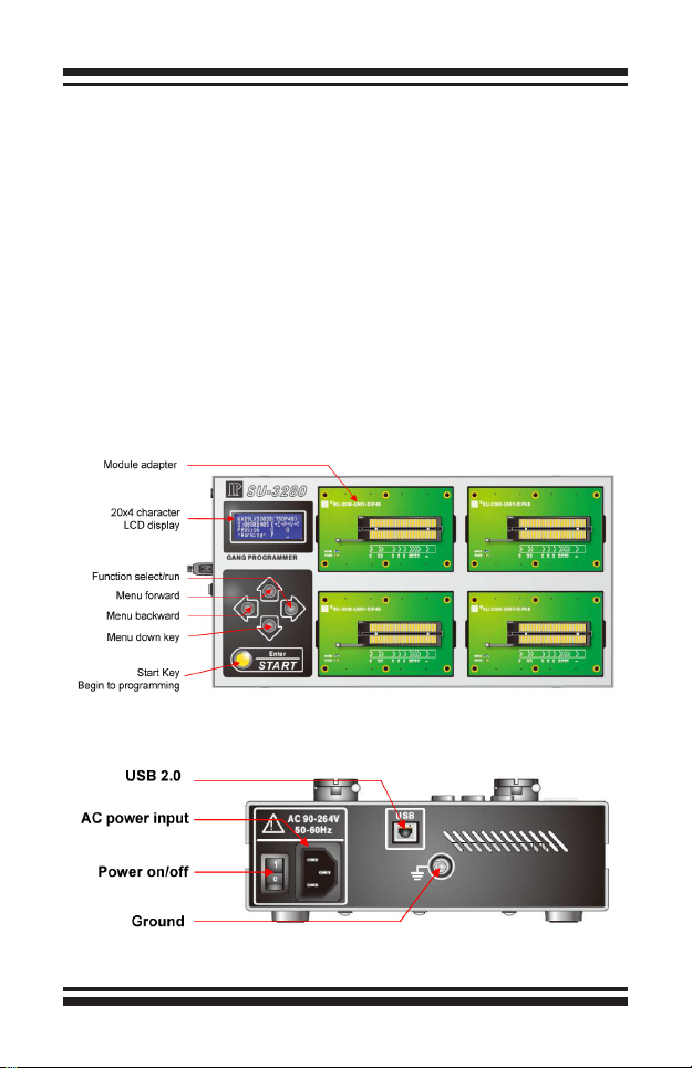
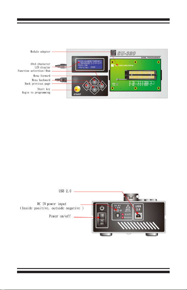
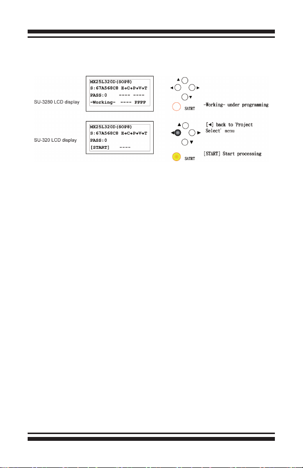
SU-3280/320 is made for high speed programming for engineering design and small &
mass production. It supports PC-based and Stand-along programming modeswhich through
LCD and keypad download the file to the inside 3.2GB memory. Moreover, SU-3280/320 adopts
modular design. With the universal DIP module, you can just use general type adapter on the market
for different package.
All of the operation, maintenance and service must adhere to the following safety
notes. We will not be responsible for any unexpected results caused by misuse.
Chapter 1 Products Overview
Chapter 2 Safety Information
1. Please turn off the power when changing the socket module. Be careful when removing the
original socket module. You must pay attention to the direction of insertion. Moreover, check
the pins situation of connectors . Make sure everything is OK, and then turn on the power
again.
2. Socket module is consumable. The IC insertion times, delicate operation, and IC surface
cleanliness all affect the quantity of contact between the socket and DUT IC and
programming quantity. When the programming fail rate increases significantly, you need to
check whether it's time to replace the socket module.
3. When programming, the programer will provide specific voltage, and if IC is misplaced or
you select the wrong IC part no, it may will damage the IC.
4. For OTP (one time programming) ICs, as they can not be programmed again, please must
be careful when operating.
5. Please pay attention to the master file version and parameter settings and
programming procedures.
6. For each new production order, must do on-board test to avoid misuse of the master file.
7. During mass production, please do random IC inspection, including programming file,
parameter setting, security setting, and certain block setting.
8. It's recommended that the operator is well trained on the operation procedures.
9. Under the warranty, please do not repair or maintain on your own unless receiving our
permission.

User's Manual
– 2 –
10. If any problem, pleas stop programming at once.
11. We will disclaim any responsibility for any loss or damage because of the above misuse.
Chapter 3 Appearance Description
3-1 SU-3280 Front panel
3-2 SU-3280 Side Panel

User's Manual
– 3 –
3-3 SU-320 Front panelr
3-4 SU-320 Side Panel

User's Manual
– 4 –
Chapter 4 Stand-alone Operation
4-1 Turn on Page
4-2 System Mode Selection Page
4-3 Project List
▲
◄►
►
[▲]/[▼] Up/down
[►] Select current item
SU-3280 Ver:1.0
►01.Project Select
02.Link to PC
SATRT
Line 1: GANG PROGRAMMER—Product description.
Line 2: Product model, SU-3280-- 4 socket modules, support IC up to 16.
SU-320-- 1 socket module, support up to 4 ICs.
Line 3: Show the system version and published date.
Line 4: Press any key to system mode selection page.
Line 1: Model name and Version.
Line 2: Execute Project select function
Line 3: Via USB to PC, execute remote function.
You can save up to 20 project File on SU-3280/320.

User's Manual
– 5 –
4-4 Project Information
4-5 Project Execution & Option
Line 1: Project name within 16 characters. You can save up to 20 project files on the menu with the
total limit 2GB.
Line 2: Part no. 20 characters at most.
Line 3: The master le check sum, 8-digit HEX.
Line 4: Programming procedure, Erase/Blank Check/Program/Verify/Protect
Line 1: Part no.
Line 2: 01. Run All - Execute programming procedure. Need to press Start button every time.
Line 3: 02. Auto Run – Execute auto run. Just press Start button once, after that, once new IC
is inserted, it will automatically start.
Line 4: Clear counter for the Pass quantity.
Line 5: Set the sensitivity of IC insertion for 'Auto Run' function

User's Manual
– 6 –
4-6 IC Processing
Line 1: IC part no.
Line 2: Check sum, programming procedure.
Line 3: PASS COUNTER, T9~T12 status, T13~T16 status
Line 4: Working Status, T1~T4 status, T5~8 status
4-7 IC Status on Socket
T1~T16( or T1~T4) Status symbol:
E→C→P→V→T: IC process, Erase/Blank Check/Program/Verify/
Protect
〝-〞 Socket Enable
〝 〞 Socket Disable
〝√ 〞 Under Auto Run, new IC placed properly
〝?〞 Under Auto Run, new IC pin scan FAIL
〝O〞 PASS, IC still on the socket.
〝o〞 PASS, IC taken off
〝X〞 Process fail, IC still on the socket.
〝x〞 Process fail, IC taken off

User's Manual
– 7 –
Chapter 5 PC Software
5-1 Installation
Please make sure the Universal IC Writer II and DataBase have been installed.
When installing SU-320 USB drivers, you will need to install 2 times. When installing
SU-3280, you will need to install 5 times. The USB drivers will be placed on the USBDrv
automatically as the image below shows. For SU-320, it will only show one Universal IC Writer
II.

User's Manual
– 8 –
5-2 Software Interface
5-2-1 Main Page
Software name and version
Project icon
Option icon
Current project name
Current model name
Project le information

User's Manual
– 9 –
Counter for record PASS, FAIL and
Total quantity.
Return to 0
Execute programming procedure,
STOP or START.
Execute Run All or Auto Run.
Disabled- After ICs placed well,
you need to press the button for
programming each time.
Enabled- No need to press the
button each time.
Stop the Auto Run procedure. The
current procedure will be
completedand stop.
Log : Show the current execute status and result.
Clear the log le

User's Manual
– 10 –
Save the log le
Show each socket IC status. SU-3280 has 4 module adapters. Each module adapter processes
4 devices at the same time.
1. UI detect
programmer ready
status.
2. When Auto Run,
place new IC status.
Under programming. Run All programming
successful
Run All programming
Fail.
5-2-2 IC Status on Socket

User's Manual
–11 –
Auto run programming
successful. And inform
user to remove IC.
Auto Run
programming fail.
And inform user to
remove IC.
Programming PASS
and user can put
the next IC.
Programming FAIL
and user can put
the next IC.
After Auto Run
programming finishes,
user placesnew IC but
does not run
programming
before removing the IC.
It will show PUT IC.
The green bar
means the last
time programming
pass result, and user
places new IC but
does not run
programming
before removing the IC.
After Auto Run
programming
finishes, user places
new IC but does
not run programming
before removing the
IC. It shows PUT IC.
The red bar
means the last time
programming fail
result, and user
places new IC but
does not run
programming before
removing the IC.

User's Manual
– 12 –
You can do add, delete and load le on the page. The maximum projects are up to 20. The
highlight is the current programming project.
Add new project le on the programmer.
Delete the project le on the programmer.
Load the programming project le.
5-2-3 Project Manager Page
5-2-4 Options Setting Page

User's Manual
– 13 –
[Message Box Clearing Selection] :
When [log] line exceeding the setting range.
[Auto Clear]: clear the log if exceeding the range.
[Auto Clear and Save]: Save and clear the log if exceeding the range.
[Limitation of The Number of Rows for Message] :
Setting the range if the log exceed, then clear or save.
[Select Log Save Directory] :
If you set the auto-save log function, the log le will save in this le. If no, the default is
'History\MLOG'.
[Options->Log Setting]

User's Manual
– 14 –
[Options->SelfTest]
You can check each site for self-test or simple LED function. You can see the result on the
Main log or display.
[Options->Information]
You can read the programmer BIOS and serial no. on the page. There are two BIOS on SU-3280/320.
[SU BIOS] Main system BIOS, the human-machine interface.
[LP BIOS] Programming BIOS

User's Manual
– 15 –
[Options->BIOS Update]
This is the function of BIOS update, [Display] shows the BIOS version which comes
with the DataBase.
When pressing the Execute, it will update the BIOS to this unit.
PS: When you update the BIOS, LED will flash for a while. After finishing the update, the unit
will reboot automatically.
There's a certain risk for updating. So, do not turn off the power when updating.
Otherwise, the devise may not be able to reboot.

User's Manual
– 16 –
[Options->Auto Run]
[Interval Time] : Set the interval time for Auto Run checking.
[Ignore Insert Detect] : Whether to ignore the Insert Detect result for IC processing.

User's Manual
– 17 –
Chapter 6 Tutorial
6-1 PC Software Operation
<Step1> To Generate project les by single-operation software.
After generating the project file, close the single-operation software. Single-operation
or SU software cannot be run at the same time. If both of them are running at the same
time, it will lead to disorder and not work.
<Step 2> Set the programmer to USB, link to PC.
Connect USB cable to PC and the programmer.

User's Manual
– 18 –
<Step3> Open SU software to load the project le
After loading the project file, the loaded file cannot be modified. If user wants to
modify it, you need use single-operation software. If the project file is on the list, select it
and click Load.
This manual suits for next models
1
Table of contents
Popular Motherboard manuals by other brands

Asus
Asus TUF GAMING B650M-PLUS WIFI quick start guide

Texas Instruments
Texas Instruments TPS2640EVM user guide

Honeywell
Honeywell 7720P Programming Instruction

Hectronic
Hectronic H6813 Hardware reference guide

Supermicro
Supermicro X11SPM-F user manual

Texas Instruments
Texas Instruments TPS746EVM-009 user guide