AN-175
9 Holt Integrated Circuits
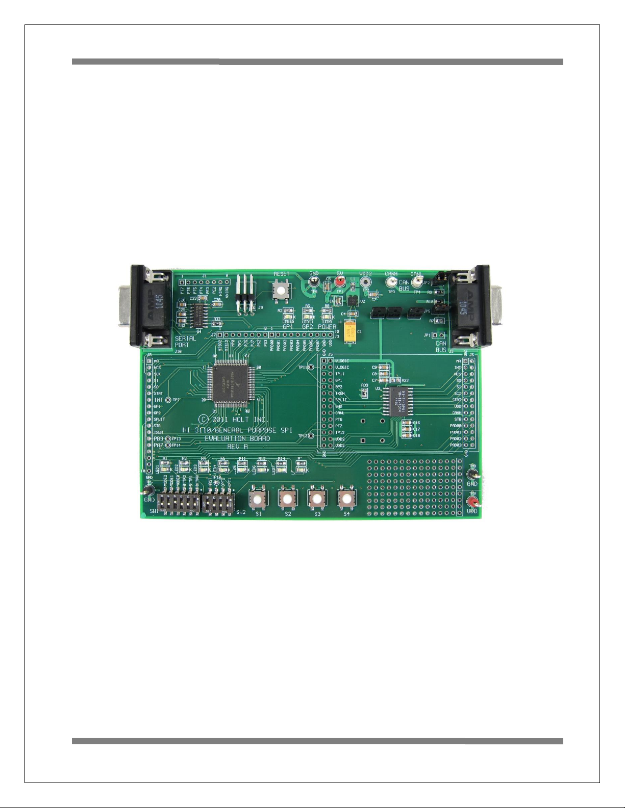
Users Guide
Mode-0: Board Test
In this mode the MCU performs a walking pattern on the GPIO pins and cycles turning on all the LEDs.
See the boardtest.c module for details and other options available.
Mode-1: Transmit Mode Standard Frames
This transmits a standard CAN frame with an incrementing 32-bit value in the first 4 bytes of the data –
field, the last four bytes will be 00. After RESET press the Button-1 to start the transmissions. A portion
of the data field will be copied to the LED1-LED4’s. They can be seen counting in this mode.
Press Button-1 to stop transmitting and print out the status registers on the serial console.
Press Button-2 to pause the transmission. Press Button-2 again to transmit one frame again.
Press Button-3 to print out the Transmit History FIFO contents on the serial console.
Press Button-4 to resume transmissions.
OPT1 switch= open, Inserts a 400us delay before each transmission.
Mode-2 Receive Mode using Polling method
To use Receive mode with an external node transmitter, set the OPT1 switch to the closed position to
disable the Receiver data frame compare feature. This will allow any data frame to be accepted.
LED1-4 will reflect the lower nibble of byte3 of the data-field.
CAN Error Detection
While receiving frames if there are any errors detected in the HI-3110 registers, TEC, REC or ERR, they
will be automatically logged on the Serial Port.
For example if ERR has a 01 value it would be shown as: ERR: 01. The other two errors will be shown
similarly.
Button-1 –Stop receiving CAN messages and print the last 64 CAN frames and the status registers on the
serial console. Press Button-4 to resume receiving CAN messages. See a partial listing of this output
below which shows the last two frames.
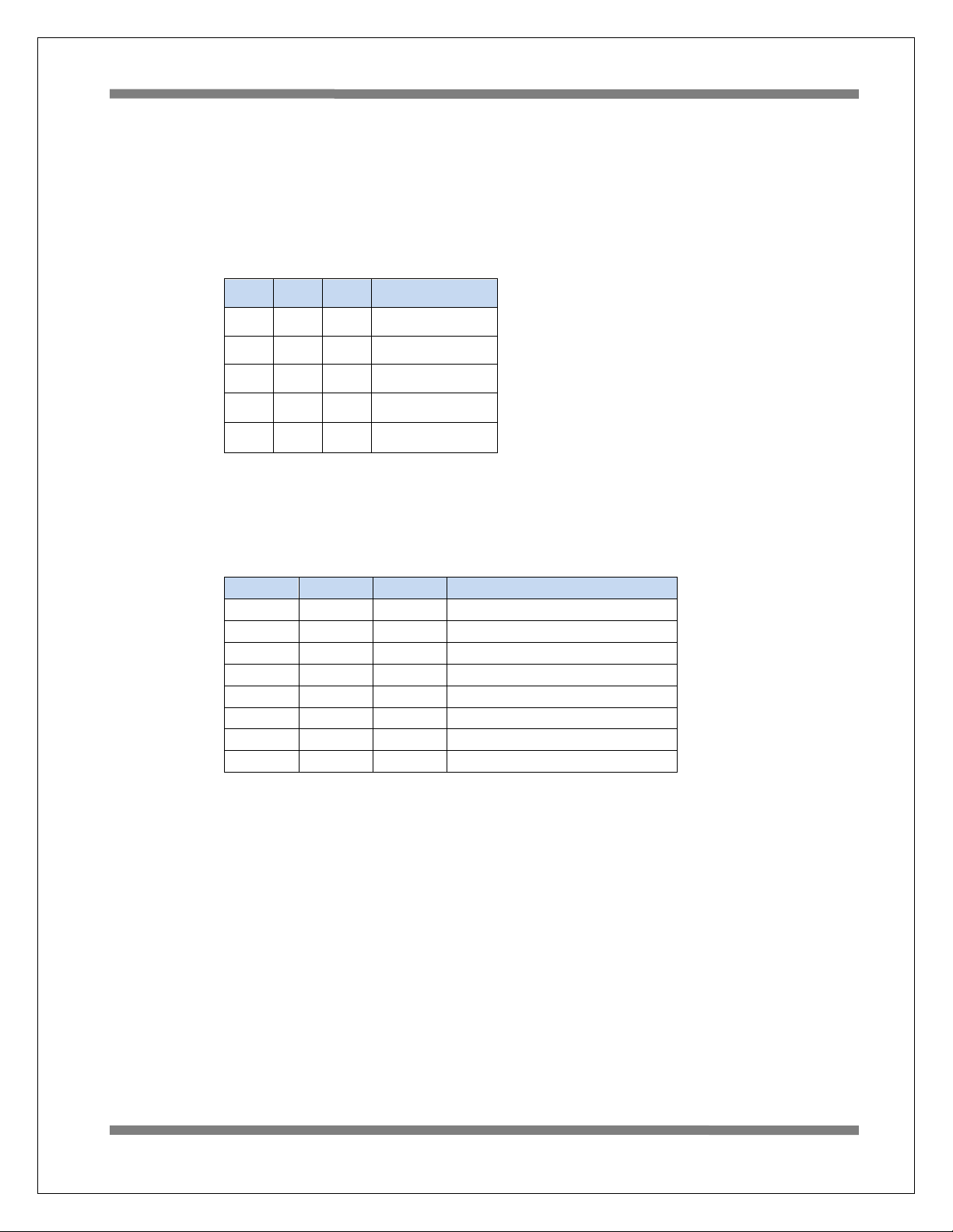
CAN Frame 62: 00 77 60 47 20 00 00 08 00 00 22 28 04 05 06 07
Standard Filter:0 TTU:77 TTL:60 BaseID:239
[r0,r1,x,x][DLC]: 08 Data-Field: 00 00 22 28 04 05 06 07