Learn to Solder Kit Hue User manual

Hue

Resistors x3
Potentiometers x3
RGB LED x1
Common Cathode
On/Off Switch x1
Hue PCB x1
Battery Holder x1
3V Coin Cell Battery x1
01. Parts

FINE SOLDER WIRE
Soldering Iron
Solder Sucker
Solder
Safety Glasses
Flush Cutters (Snips)
Helping Hands
110V
60W
Soldering Iron
02. Tools
OPTIONAL
RECOMENDED
SOLDER SUCKER SS-4000

Above is the correct setup for creating a
strong solder joint. Your goal is to heat both
the lead of the part being solder and the
solder pad. Then introduce the solder itself. By
heating the lead and pad correctly the solder
will flow around them to create a strong joint.
Your soldering iron should be set to at least
450F and less than 700F. If your solder iron
does not have a temperature dial no problem!
Just plug it in a go. Hold the tip of the iron to
the lead and pad for about three seconds
before introducing the solder. Don’t worry if
you heat up the board a bit, it is designed to
withstand hot temperatures.
Hold the solder between your forefinger and
thumb about four to six inches from the end.
The solder is going to melt really quickly so
you don’t want your finger to be too close to
the end. Touch the solder to the solder pad. It
should liquify almost instantly and flow into
the joint. Move the solder around a bit to
cover the entire solder pad. You don’t need
very much to create a clean solder joint. It
should only take a few seconds.
Pull the solder away first and then the
soldering iron. Viola! You have just created
your first soldering joint! Your solder joint
should look something like the image below.
Soldering
Iron Tip
Lead of Part
Solder Pad
Solder
03. Technique

Soldering Iron
GOOD OKAY
A little metal mountain
resembling a hershey kiss.
Fully covered solder pad, you
should see no more gold.
The solder is not fully on the
solder pad. You still see some
gold visible. Give it a another
try. Just reheat the solder joint
and add a little more solder.
A blobby solder joint that is
more spherical. You can use
less solder next time. The
electronics should still work!
BAD
04. Step-By-Step
Assembly Instructions
Start with the first resistor. This resistor
is going to go into the place on the
board labeled R1. Resistors are
bi-directional meaning it doesn't
matter which way they're rotated when
you put them in. First remove the tape
on both ends of the resistor leads. Then,
bend the legs of the resistor and slide it
into its home on the printed circuit
board. Once the resistor is in place it
helps to bend them slightly outwards
so the part doesn’t fall out.
1.
STEP 1: RESISTORS
110V
60W
Soldering Iron

Now it’s time to start soldering! Flip over
your board so that the legs of your resistor
are sticking up in the air and turn on your
soldering iron. Be careful it will get hot!
Give yourself a length of solder, 4 to 6
inches. Then, holding the solder in one
hand and your soldering iron in the other,
use the tip of your iron to heat up both the
leg of the resistor and the gold ring around
the hole. Slowly feed in your solder into this
joint until you've made a solid connection.
Viola! One solder joint complete!
Do the same on the other leg of your
resistor then use wire snips or scissors
to cut the extra length of resistor leg
that is not needed. Be careful not to
cut too close or you might damage
your solder joint.
Follow the same process for Resistor 2
and Resistor 3.

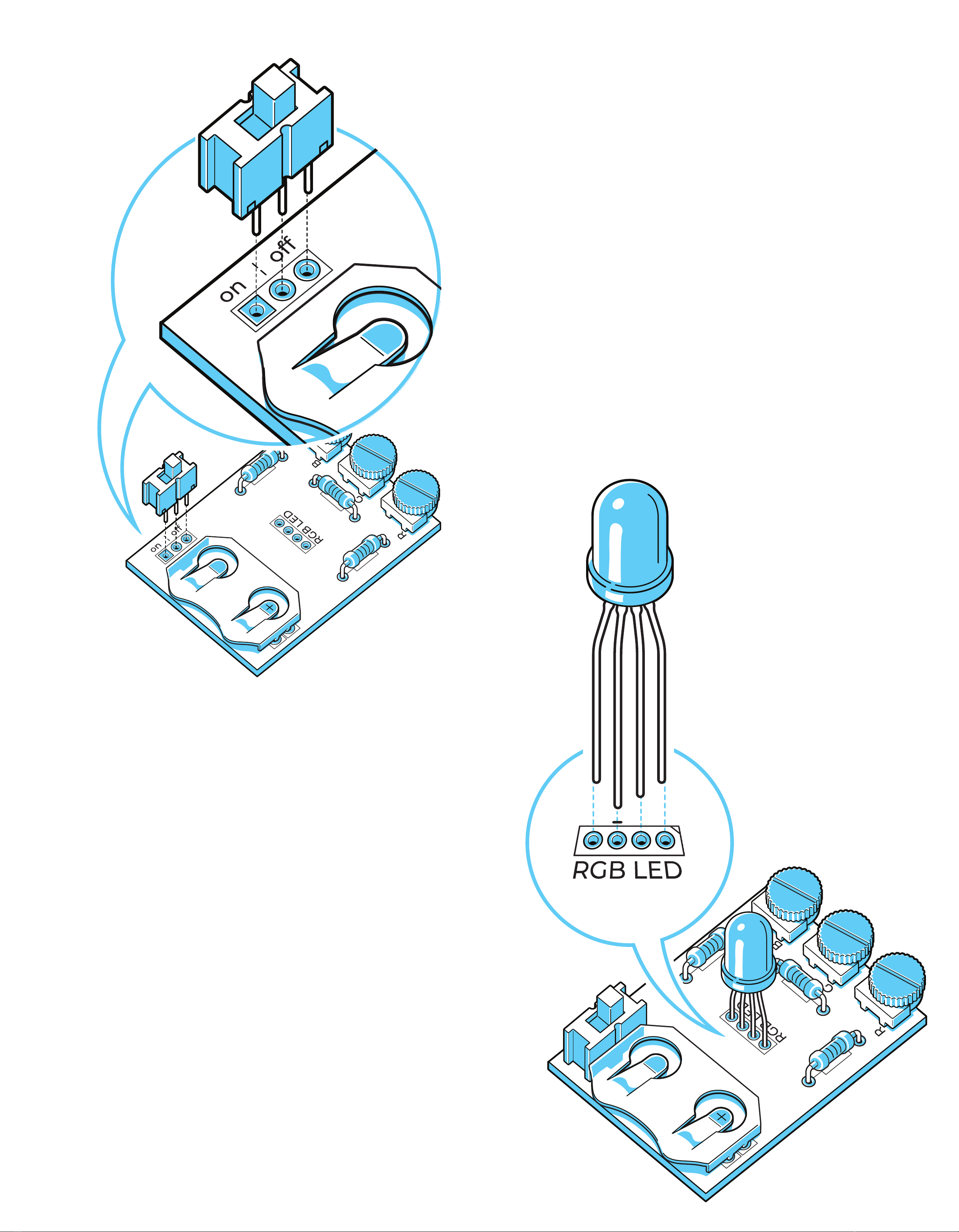
Next up is the potentiometers. These are
used to control the amount of current
going to each color LED varying the
brightness. More current, brighter color,
less current, less bright. These parts
should be inserted with the black knob
hanging over the edge of the circuit
board. This will allow you to easily turn
the potentiometers and change the
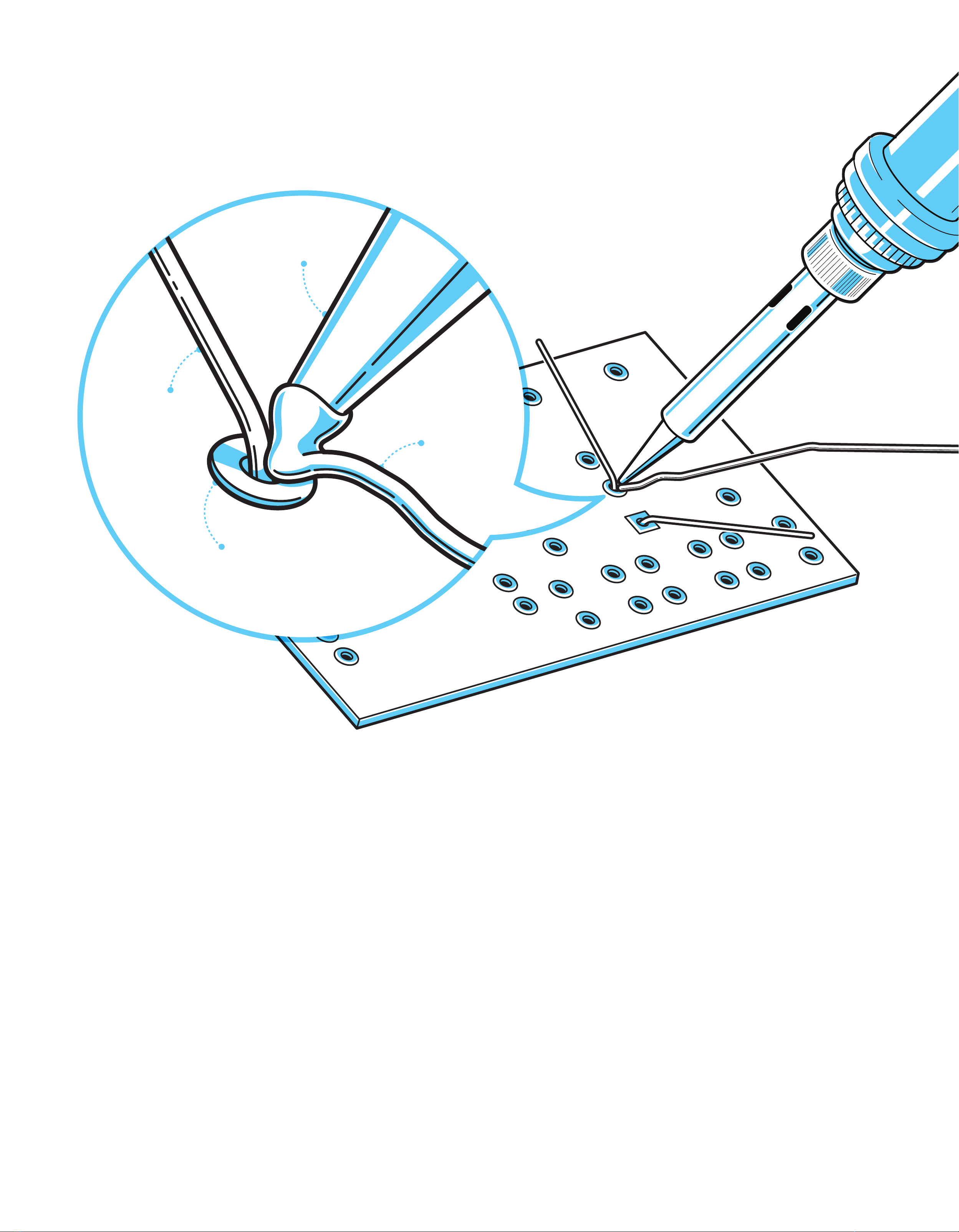
colors. Heat the leg of the potentiometer
and feed in the solder to create the
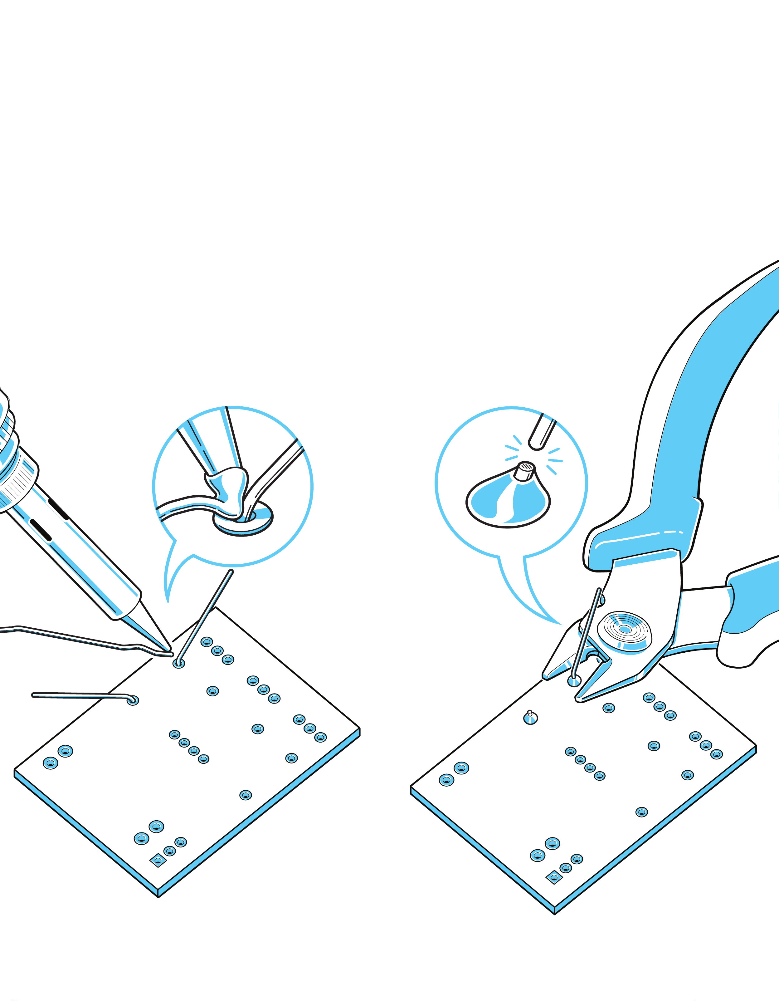
solder joint. Be careful, the leads are
close together and can be shorted. If you
connect two joints together by accident
you can remove the solder by using
either a solder sucker or solder wick.
Complete the same process for
Potentiometer 2 and 3.
2.
3.
STEP 2: POTENTIOMETERS
Place the legs of the battery holder
through the PCB holes. Do not place
the battery in the batter holder yet.
Batteries should not be heated with a
soldering iron, it can make them
unstable. Once the part is solder you
will be able to slide in the CR2032
battery. Flip the PCB over and solder
the connections. The orientation of the
battery holder matters since once all
the components are in place there will
only be one way to slide the battery in.
The half oval cut out should be
positioned at the edge of the PCB.
STEP 3: BATTERY HOLDER

Next we add the On/Off switch.
Without this component the circuit
would be always on and the battery
would drain quickly. The orientation of
this part doesn’t matter in this circuit.
The switch will connect the middle pin
with either the top or the bottom pin
depending on how it positioned.
4.
5.
STEP 4: ON/OFF SWITCH
The orientation of the
RGB LED matters. If it is
inserted incorrectly the
LED will not turn on.
This is a common cathode with means
all three colors share a common ground.
The longest pin (marked with a red
circle and dash in the picture) is the
common ground pin. The other three
pins control the three colors, red, green,
blue. The longest pin must be inserted
into the hole marked with a dash on the
printed circuit board. Press the LED
through the PCB. The LED will not be
completely flush with the board
because of how close the leads are, we
need some space to solder! Very
carefully solder the leads on the LED.
These are the trickiest connections of
this kit. Once the connections are
complete snip the leads of the RGB LED.
STEP 5: RGB LED
Soldering Iron

6.
Insert the batter and flip the On/Off
Switch. Watch it light up! Rotate the
knobs to control the colors and create
a beautiful rainbow light show.
Contact Rocket Department at ideas@rocketdept.com
STEP 6: ENJOY!
QUESTIONS? COMMENTS?
On
110V
60W
Table of contents
Other Learn to Solder Kit Toy manuals