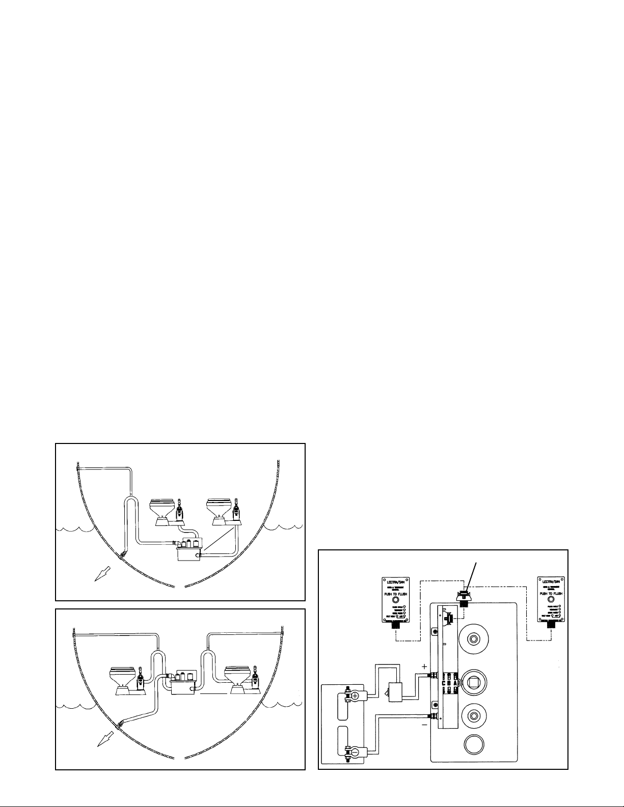
LECTRA SAN EC User manual

1
TREATMENT TANK
CONTROL INDICATOR PANELSALT FEED TANK
EC
Installation and Maintenance Instructions
THE FOLLOWING ARE CAUTIONARY STATEMENTS THAT MUST BE READ AND FOLLOWED
DURING BOTH INSTALLATION AND OPERATION
WARNING: Raritan Engineering Company, Inc. recommends that a qualified person or electrician install
this product. Equipment damage, injury to personnel or death could result from improper
installation. Raritan Engineering Company, Inc. accepts no responsibility or liability for
damagetoequipment,orinjuryordeathtopersonnelthatmayresultfromimproperinstallation
or operation of this product.
WARNING: HAZARD OF SHOCK AND FIRE - Always use recommended fuse/circuit breaker and wire
size.
WARNING: HAZARD OF FLOODING - Always shut off seacocks before leaving boat unattended.
Double clamp all hose fittings below the waterline, check hose clamps frequently for integrity.
WARNING: TheLectra/SanECoperatesonanElectrochemical principle. Introductionofanysubstanceother
thansalt water, humanwasteortoilettissuemaycause heat buildupandextensivedamage. Ifany
other substance is introduced by accident, the Lectra/San EC must not be turned on until entire
system is flushed out with water.
INTRODUCTION
The Lectra/San EC is a U.S. Coast Guard Certified
Type I Marine Sanitation Device for uninspected
vessels less than 65 feet in length. Lectra/San EC
accommodates most marine toilets. It can be used
with one or two toilets (see page 10). It is designed
and approved to treat waste for overboard discharge
inareasthatarenotdeclaredaNo-Dischargezoneby
the U.S. Environmental Protection Agency. The
total system is made up of three basic parts:
TheControlIndicatorPanel-Beginsthetreatment
cycle and can also be connected to flush an electric
toilet at the same time (single toilet application).
Dimensions: 4 1/2"H x 2 3/4"W x 1"D
The Treatment Tank - Consists of two chambers
and an electrode pack that temporarily converts
salt water into a powerful bactericide for the
durationofthetreatmentcycle. Thetopofthetank
containsthe controlmodule andits protectivecover.
Dimensions: 16"W x 8 3/4"D x 13 1/2"H
Salt Feed Tank - Necessary to supply a saturated
salt solution when not operating in water of ocean
salinity. Dimensions: 9"W x 9"D x 7"H
Additional parts included: 1 1/2" hose adapters
(2), 1 1/2" NPT Intake Plug, 90°1 1/2" slip PVC
fitting, ribbon cable, salt tank attachments, Owners
manual, warranty information, template for Opera-
tion Instruction Wall Placard Indicator Panel and
U.S.C.G. Type I Equipped label.
NOTE: To comply with U.S.C.G. Regulations, the
instruction wall placard should be placed near the
control indicator panel and the "U.S.C.G. Type I
Equipped" label MUST be in a visible location.
OPERATION
Press yellow button (Push to Flush) to activate
Lectra/San EC system.
NOTE: Toilet must not exceed 1.5 gallons of
waste water during any total flush cycle.
1. If your toilet is electrically connected with the
Lectra/San EC(seeFigs.9and9A), itwill flush
automatically. You may flush the toilet as
necessary at 10 secondintervals within the first
40 seconds (duration of the FLUSH cycle).

2
FLUSH CYCLE ➀
TREATMENT ➁
CHECK FUSES ➂
SALT HIGH ➃ LOW ➃
LECTRA/SAN
HEAD & TREATMENT
CONTROL
PUSH TO FLUSH
Fig. #1
Light Sequence:
➀Flush toilet only while
green flush cycle light is
on (first 40 sec.).
➁Treatment light (green)
will remain on for entire
cycle.
➂Check Fuse light (red) on:
See Troubleshooting.
➃High Salt or Low Salt
light (amber) on: Treat-
ment will continue. See
Troubleshooting.
2. If using a manual toilet or electric toilet installed
on a separate circuit, Lectra/San EC must be
activated before flushing the toilet.
TREATMENT CYCLE
(How it Works and What it Does)
The flushing action of the marine toilet discharges
waste and water into the first chamber of the Treat-
ment Unit. There, waste is macerated and treated.
Proprietary electrode plates are electrically ener-
gized to temporarily convert salt water into a strong
bactericide, hypochlorous acid. This solution treats
thewasteby eliminatingbacteria and viruses,then it
reverts back to the original state of salt and water.
Upon the next flush of the toilet, additional waste
enters the first chamber, forcing some of its treated
contents into the second chamber. While the new
waste is being macerated and treated in the first
chamber, the contents of the second chamber are
stirred and given additional treatment. A mixer is
locatedinthesecondchambertopreventsludgefrom
accumulating and to ensure uniform treatment of its
contents.
Successiveflushesmovetheoriginaltoiletdischarge
through the Lectra/San EC and eventually over-
board. When the discharge enters the water it is
completely treated and no harmful elements are
added to the environment.
MAINTENANCE
IMPORTANT: Cleaning and Winterization
instructionsarebasedonhaving an electric toilet
connected to the Lectra/San EC for single button
operation.
Periodically inspect the unit for leaks and check for
loose plumbing and electrical connections.
WARNING: If the toilet is wired on its own
circuit,ormanuallyoperated, make sure power
toLectra/SanECisOFF priortocleaningand/or
winterizing.
CLEANING
WARNING: DO NOT activate the Lectra/San
EC during this procedure. Discharge seacocks
must be in OPEN position.
NOTE: The following procedures pertain to use
with single button operation toilets.
Completely read all instructions before begin-
ning the procedure.
Treatment Tank:
1. RemovethethreefusesfromtheControlModule
(locatedonthetopoftheTreatmentTank). Mark
each fuse for replacement purposes. Fuse re-
moval will permit operation of an electric toilet
without activating the Lectra/San EC.
2. Shutoff intakeseacocktothetoilet,ifnecessary.
Once fuses have been disconnected, flush bowl
as dry as possible.
WARNING: Beforeusingacid,observesafehan-
dling instructions on container.
3. Add one pint of muriatic acid, 31% by weight
(availablefromhardwarestores), toatwogallon
plastic bucket of fresh water.
4. Pour the solution into the toilet and flush the
toilet (press button) as dry as possible so the
solution is forced into the treatment unit.
5. Pour an additional gallon of fresh water into the
toiletbowltodilutetheremainingacid. Letstand
for 45 minutes before flushing toilet.
6. Open intake seacock or water supply. Flush the
toilet as often as possible during the flush cycle.
(DuringtheTreatment Cyclethe toiletcannot be
flushed.) Allow the Treatment Cycle to finish.
Repeat four times.
6a. For toilets which are not controlled by the
Lectra/Sancontrolopenintakeseacockand water
supply. Flush the toilet at least 15 times for 15
seconds each time (minimum of 10 gallons rinse
water) to effectively dilute and discharge the
Lectra/San EC contents.
DO NOT FLUSH TOILET AFTER THE
FLUSH CYCLE LIGHT GOES OFF.

3
7. Reinstall all three fuses in proper sequence, per
Fig. #10 and specifications table.
Salt Feed Tank:
1. Thoroughly rinse and wipe out tank.
2. Check to make sure the small vent hole in tank
cap is not blocked.
3. Rinse out connection hose with fresh water.
4. Clean T/Check Valve assembly.
STORAGE
Short Term Storage
NOTE: Failure to perform the following may
result in an odor problem and contribute to min-
eral buildup in the system.
If the boat's toilets are not going to be used for up to
one week, activate the treatment unit and flush the
toilet(s) twice for the complete flush cycle before
leaving the boat.
Long Term Storage
If the boat's toilets are not going to be used for over
a week, follow short term storage instructions and
also purge the toilet hoses and Lectra/San EC with
fresh water.
See Recommissioning and Start up.
WINTERIZATION
WARNING: DO NOT USE ANTIFREEZE IN
LECTRA/SAN EC.
1. Run Treatment Cycle five times, flushing the
toilet for the entire duration of the 40 second
flush cycle.
2. Close seacocks.
3. Disconnect and drain hoses.
4. Usingapump,removewaterfromtheTreatment
Unit (through crossover cap).
5. The electrode pack should be inspected and
cleaned. Remove the Treatment Unit Cover and
pull out the electrode pack. Rinse with fresh
water and clean with a stiff non-wire brush.
Empty any remaining water from the tank.
RECOMMISSIONING & START UP
1. Reconnect hoses and open seacocks.
2. RemovethethreefusesfromtheControlModule
(locatedonthetopoftheTreatmentTank). Mark
Fig. #4 - Lectra/San EC with vented loop (below waterline)
Below Waterline Installation Requires Vented Loop Between
Lectra/San Treatment Unit and Thru-Hull Fitting
Fig. #3 - Lectra/San EC with holding tank (above waterline)
Lectra/San EC
Lectra/San EC
Raw Water Strainer
TWK
Intake
Thru-Hull
and Seacock
Intake
Thru-Hull
and Seacock
Discharge
Thru-Hull
and Seacock
Discharge
Thru-Hull
and Seacock
Y Valve
PHII Marine
Toilet
PHII Marine Toilet
TWK
Raw Water
Strainer
Vented
Loop
Vented
Loop
Deck Pumpout
Vented
Loop
Vent Outside
Hull or Deck
Vent Outside
Hull or Deck
Fig. #2 - Lectra/San EC with Vented loop (above waterline)
each fuse for replacement purposes. This will
allow operation of an electric toilet without acti-
vating the Lectra/San EC.
3. Flush the toilet four times, allowing approxi-
mately two gallons of salt water to enter the
Treatment Tank.
4. Reinstall the three fuses in proper sequence,
per Fig. #10.
INSTALLATION
Use Figures #2 through #4 which show some instal-
lation options. (Drawing are not to scale.)
WARNING: Below waterline installations must
includeaventedloop. Thetopoftheloopmustbe

4
above the waterline at maximum heel to prevent
siphoning.
MOUNTING
Treatment Unit
Location: TheTreatmentTank shouldbe withinsix
feet of the toilet, with the tank located at the same
level or lower than the toilet's discharge. If the tank
is at the same level, or slightly above the toilet, a
vented loop must be installed between the toilet and
the Treatment Tank (see Fig. #2). If the treatment
unit must be mounted more than a few inches higher
than the toilet, contact Raritan Customer Service.
WARNING: DO NOT locate in an area where
ambient temperature exceeds 120oF.
Securing Treatment Tank:
1. Make mounting frame (Fig. #5).
2. Secure mounting frame using suitable fasteners.
3. Use3/4"mountingstrapstosecuretanktoframe
(see Fig. #5). A 3/8" rubber pad (available at a
hardwarestore)placedunderthetankwillhelpto
reduce vibration and noise.
PLUMBING
Use high quality, smooth interior 1 1/2" I.D. sanita-
tion hose to avoid odor problems, available from
Raritan by the foot (part #SH). Discharge from the
toilet enters either side of the Treatment Tank and
exits from the fitting on top of the lid.
1. Connect Lectra/San EC to marine toilet per Fig-
ures #2, #3 or #4. Do not route hose into dips or
valleys and avoid 90o fittings where possible.
2. Use teflon tape or nonpermanent thread sealing
compoundonthreadedPVCfittingsandconnec-
tions.
3. Determinetheorientationofthedischargeelbow
provided before gluing with PVC Cement.
4. Double clamp all hose fittings below the water-
line.
Control Indicator Panel
1. Locate an area in the head compartment where
the indicator lights will be readily visible.
2. Usingtemplateprovided,markthecutoutforthe
panel. Do not cut outside of template markings.
3. Route ribbon cable between panel and Lectra/
San EC Treatment Unit. Secure ribbon cable
with cable holders every 18 inches, taking care
nottopuncture the insulationor crimp thecable.
4. Plugintheribbonconnection(Fig.#6)toindica-
tor panel and mount panel using four #6 screws.
SaltFeedTank: (SaltFeedTankisneededwhenthe
boat will be in fresh water/brackish water.)
1. Assemble the salt feed tank per Fig. #7A.
2. Locate Salt Feed Tank within 6 feet of toilet and
at same level as bowl. Secure tank. Make sure
the tank is accessible for refilling.
3. Attach the T-check valve and tubing to the Salt
Feed Tank.
4. AttachT-checkvalve inthe intakeline(suction)
of the toilet. Remove the ball and spring in
Raritan PHII models (Fig. #7).
5. In a separate container, combine five pounds of
rock salt with two gallons of warm water and
allow to dissolve overnight. Pour off water into
tank (this is a saturated salt solution). The salt
remaining in the bottom may be used the next
time.
2
1
To remove, spread wings
and cable will pop out of
connector.
Wings in extended position
while making connection
When cable is pushed into connector wings
will snap into proper locking position.
T Check Valve (incl. w/Salt Feed System)
Fig. #7 Raritan PHII with Salt Feed Tank
Remove Ball and Spring
Fig. #6 - Ribbon Connector
Fig. #5
1"x1"
14 1/8" 7"
MountingStraps*
Wooden frame
surroundingtank*
Vibrationisolationpad
beneathtank (Optional)*
3
* not included

5
Fig. #8
To Battery Negative
To Protected Battery Positive
(fuse or circuit breaker)
1203B1
31-304C
31-304A
(ASSY)
31-302
31-304W
31-305
31-301
➀
T-CHECK VALVE EXPLODED VIEW
AND PARTS LIST:
1 Valve Body 31-307D
2 Siphon check valve 31-308W
3 Ball CH12
4 Spring CH8
5 O - Ring 31-307E
6 Discharge Adapter 31-307D1
Salt Feed Tank complete - 31-3001
T-Check Valve complete - 31-307W
SALT FEED TANK EXPLODED VIEW AND PARTS LIST:
Fig. #7A
Lectra/San EC SPECIFICATION TABLE
ELECTRICAL:
Voltage Nominal 12VDC 24VDC 32VDC
Voltage Minimal 11.5V 22.0V 31.0V
Power 1.7 amp hr 1.5 amp hr. 1.5 amp hr.
Current 50 A 42 A 35 A
Fuse/Breaker 60 A 50 A 50 A
Length of circuit: Wire Gauge
0-15' #6 AWG #8AWG #10AWG
15'-25' #4 AWG #6AWG #6AWG
26'-50' #1 AWG #4AWG #6AWG
☞☞
☞☞
☞NOTES: 1. Wiredistanceisdeterminedbymeasuringfrom
the battery to the Lectra/San and back again.
2. Minimal Voltage is read across the electrode
packwhile thesystem is operating in thetreat-
ment (2nd) cycle.
3. Requires ocean grade salinity for proper con-
ductivity.
Max Amperage: 12VDC 24VDC 32VDC
Mixer Motor amp 5 4 4
“A” Fuse Type MDL 6 1/4 6 1/4 5
Electrode Pack 25 22 22
“B” Fuse Type MDL 35 30 30
Solid Reduction Motor 20 16 9
“C” Fuse Type MDL 30 25 20
Gallons of Waste Treatable/Day: 576
Maximum Roll/Pitch Angle: 30°
Maximum Temperature Exposure: 120° F
Maximum Total Flush Volume: 1.5 Gallons/Flush
☞Atlantesowners: Use deodoranttank forsalt
mixture, reduce concentrate ratio by 1/2.
ELECTRIC WIRING
WARNING: Danger of electric shock. Be
sure to disconnect power.
1. Run supply wire to Positive and Negative
terminals using specification table for wire
size and circuit breaker.
2. Connect wires to Positive and Negative ter-
minals on Treatment Tank (Fig. #8).
3. Connect ribbon cable, (#31-404) from Con-
trol Indicator Panel to the Control Module
(Fig. #10). Secure strain relief.
4. If you wish to flush an electric toilet (other
than the Atlantes) by pushing the Lectra/San
EC Control Indicator Panel, a Raritan Con-
tinuousDutySolenoidmustbeinstalledand
wired per Fig. #9. (Atlantes see Fig. #9A.)
Failure to follow this correctly will result
in damage to the Lectra/San EC control
board and will void warranty.
IMPORTANT: Check polarity before turn-
ing on power.
5. Follow start up procedure under Recommis-
sioning and Start up.
WARNING: Allcontrolboardsarepretested
at the factory. Burnt control board compo-
nents or foils are a result of improper wiring
by the installer. Board replacement in these
cases are not covered by Raritan's limited
warranty.
➂ ➃ ➄ ➅
➁
1203B1 O-Ring
31-301 Salt Feed Tank
31-302 Salt Feed Tank Cap
31-304A Adapter Assembly
31-304C Metering Thumbwheel
31-305 1/4" Tubing

6
* Use Only Raritan part #CDS12, 24 or 32; Other solenoid
relays may damage the Circuit Board, voiding warranty.
Fig. #9A
Ribbon Cable Connection
10 pin (orange) connector
Fig. #10
+
-
LECTRA/SAN
PUSH TO FLUSH
Lectra/San EC
Treatment
Tank
Ribbon
Cable
+ -
Lectra/San EC
Circuit Board
Lectra/San EC
Switch Panel
POS NEG
Fig. #9
"BAT"
Isolated Coil
Solenoid
Relay *
Electric
Toilet
Battery
JQC203
JQC101
12-18 AWG
Purple
Yellow
Fuses/Ckt
Breakers
Orange
(macerator motor) Brown
Red(electrode plate)
Orange
(mixer motor)
Ribbon Cable Clamp
Ribbon Cable
Purple
Yellow
Location of circuit boards Lectra/San EC
(Electronic Control)
Atlantes Toilet
Indicator
Panel
Atlantes
Circuit Board
Refer to Atlantes
Installation Instructions

7
CORRECTION
A1. Check circuit breaker or main fuse to unit.
Check connections to Positive and Negative
terminal.
A2. Check and clean connectors by disconnecting
and reconnecting.
A3. Replace Control Board.
A4. Replace switch panel assembly.
A5. Replace ribbon cable.
B1. Check fuse A, B or C on Treatment Unit.
B2. Check voltage at Treatment Unit and at battery
during Treatment Cycle. See Specification
Table for minimum voltage.
B3. Replace board.
C1. Add salt to system.
C2. Clean electrode plates (see maintenance).
C3. Check voltage at Treatment Unit and at battery
during Treatment Cycle. See Specification
Table for minimum voltage and wire size.
C4. Increase salt tank flow. Contact Raritan
Customer Service.
D1. Reduce salt concentration; add fresh water to
toilet bowl.
E1. Check voltage at Treatment Unit and battery
during Treatment Cycle. See Specification
Table for minimum voltage and wire size.
E2. Isolate circuit.
F1. Rub cloth on outside of hose. If odor transfers
to cloth; all discharge hose must be replaced
with high quality discharge hose (Raritan
#SH).
F2. Check for liquid leaks (not gas). Follow
discharge hose from toilet to Treatment Tank
until leak is located and corrected.
F3. See Page 3 (STORAGE).
F4. System designed to treat each flush - the unit
must be activated at each flush.
F5. Clean dirty electrode plates or replace.
F6. Replace the B-Fuse. Test the electrodes.
Replace if necessary.
TROUBLESHOOTING
PROBLEM
A. When button is pushed,
nothing happens; system
inoperative.
B. "Check Fuse" light is on.
C. Low salt light on. The low
salt indicator is lit when the
electronics in the Lectra/
San EC control board
determines that not enough
current is flowing through
the electrodes. This can be
caused by any combination
of C1 - C4 or all of them.
D. High salt light on.
E. Inconsistent operation
(check fuse light or incom-
plete cycling).
F. Sewage odor.
POSSIBLE CAUSE
A1. No power to unit.
A2. Open or loose connection.
A3. Damage to Control Board.
A4. Inoperative switch panel assembly.
A5. Damage to ribbon cable.
B1. Fuse blown.
B2. Low voltage at Treatment Unit.
B3. Damage to control board.
C1. Low salt.
C2. Dirty electrode plates.
C3. Low voltage at Treatment Unit.
C4. Water too cold.
D1. Too much salt.
E1. Drop in line voltage.
E2. Other equipment operating on
same electric circuit as
Lectra/San EC.
F1. Odor permeating through dis-
charge hose.
F2. Treatment Unit has leak.
F3. System not stored properly.
F4. Lectra/San not being activated
consistently.
F5. Damage to electrode plates; Plates
not drawing enough current.
F6. B-Fuse blown - electrodes not
being activated.
If above troubleshooting does not solve the problem, contact your dealer or Customer Service at Raritan.

8
Item Part No. Description
13
14
2
15
22 1
3
2
20
21
6
10
16
11
9
78
10
11
17
8
18
719
14
21
4
4
5
5
12
2
EXPLODED PARTS VIEW OF
COMPLETE TREATMENT UNIT
1 32-102** Mixer Motor 2 1/2'' Dia. 12 VDC
1 33-102** Mixer Motor 2 1/2'' Dia. 24 VDC
1 34-102** Mixer Motoer 2 1/2" Dia. 32 VDC
2 31-121 Hose Fitting
3 31-120 Discharge Elbow 90
4 M30 Electrode Lug Nut, 1/4''-20 Brass (4)
5 M31 Electrode Flat Washer, 1/4'', Brass (4)
6 31-113-1 Cover Hold Down Bolt, 10-32x3/4'' (16)
7 31-103 Motor Shaft Bushing (2)
8 31-106 Motor Hold Down Bolt,10-32x7/8'',S/S(6)
(Hold down bolts must be completely
covered with silicone caulk before final
reassembly to prevent leaking.)
9 31-109 Mixer Impeller
10 31-110-1 Impeller Bolt, 12-24x5/8'', S/S (2)
11 31-110-2 Impeller Lock Washer, #12, S/S (2)
12 31-114 Cover Hold Down Nut, 10-32 (18)
13 31-115 Treatment Tank
14 31-122 Intake Plug
15 32-5000 Electrode Pack 12 VDC
15 33-5000 Electrode Pack 24 VDC
15 34-5000 Electrode Pack 32 VDC
16 31-112 Cover Gasket
17 31-108 Macerator Set Screw, 8-32x3/16'', S/S
18 31-107 Macerator Impeller
19 31-101W Treatment Cover (Inc. items 7, 20 and
21)
20 31-104 Crossover Plug
21 31-102 Motor Shaft Seal (2)
22 32-101** Macerator Motor 3'' Dia. 12 VDC
22 33-101** Macerator Motor 3'' Dia. 24 VDC
22 34-101** Macerator Motor 3'' Dia. 32 VDC
31-3001 Salt tank assembly (not shown)
32-4000* 12 V DC Complete Treatment Unit
(Items 1-22)
33-4000* 24 V DC Complete Treatment Unit
(Items 1-22)
34-4000* 32 V DC Complete Treatment Unit
(Items 1-22)
* Less Control Box Assembly
**NOTE: When replacing existing or new motor(s), apply
silicone caulk over motor - hold down bolt heads. Dispense
enough sealant to cover an area three times greater than the
bolt heads to avoid leaking through bolt holes.

9
20
22
12
1
2
23
23 25 11
13
3
14
5
7
16
31 14
26
24
32
8910 810
9
10
9
8
810
921
11 1012
24
24
24
33
30
23
5
12
17 15
17
8
6
9
4
25
23
( ) Indicates Total pieces required
Item Part No. Description
1 31-460 Control Cover
2 CH26 8-32 x 7/16" Truss head screw (2)
3 31-462 Mounting Plate
4 32-401 Control Board Assy. - 12V
33-401 Control Board Assy. - 24V
34-401 Control Board Assy. - 32V
5 AM06012 Solenoid Relay (2) - 12V
AM06024 Solenoid Relay (2) - 24V
AM06032 Solenoid Relay (2) - 32V
6 RBS50 Shunt Assy.
7 31-402A Wiring Harness Assy.
8 M30 1/4 - 20 Brass Nut (6)
9 HLWQB 1/4" Lockwasher (6)
10 M31 #14 Brass Flat Washer (7)
11 HSB1 1/4 - 20 Brass Cap Screw (2)
12 RNI Nylon Shoulder Washer (3)
13 1119A 1/4 - 20 x 1/2" S/S Hex Head
Machine Screw (4)
14 1118 1/4" External Tooth Washer (5)
15 1226B 1/4 - 20 S/S Hex Head Nut (4)
16 31-476 Nylon Spacer Washer (2)
17 ED1N4002 Diode (2)
20 F31-480 Nylon Stand Offs: PCB Supports
(4)
EXPLODED PARTS VIEW
OF CONTROL MODULE
Item Part No. Description
21 F069 Gray Fiber Flat Washer
22 F31-478 Threaded Rod 1/4 - 20 x 2" Brass
23 5/16 - 24 Nut (4)
24 5/16 Lockwasher (4)
25 #6-32 Screw
26 31-464 Bracket
30 31-232 Fuse Block
30A 32-218 MDL 6 1/4 Fuse
30B 32-219 MDL 35 Fuse
30C 32-220 MDL 30 Fuse
31 31-466 Bracket
32 31-468 Bracket
33 31-470 Cond. Bracket
32-402 12V Control Box Assy. (incl. all
above parts except 1 and 2)
33-402 24V Control Box Assy. (incl. all
above parts except 1 and 2)
34-402 32V Control Box Assy. (incl. all
above parts except 1 and 2)
31-403 Indicator panel assembly (not
shown)
31-404 Ribbon cable (not shown)
☞NOTE: ALL PART #'S BASED ON A 12V SYSTEM,
ALL OTHER PART #'s, CONTACT RARITAN

10
TheLectra/SanECTypeI MSDcan beconnected to
twomarine toilets. However,thetwo toiletsmustbe
in close proximity to:
1. Reduce the pressure requirement to move waste
through the connecting hose.
2. To decrease the possibility of untreated sewage
remaining in the lines.
The Lectra/San EC Treatment Tank should be lo-
cated midway between the two toilets. The maxi-
mumdistancefromeithertoilettothetankshould
not exceed six feet.
A kit is available for field conversion to dual toilet
operation:
Lectra/San EC Dual Control Component part
#LSTEDC (for 12 V units):
1. Control Indicator Panel with ribbon cable at-
tached.
2. Salt Feed Tank complete.
INSTALLATION
1. Adding second toilet - Install Lectra/San and
first toilet per manual, then add second toilet by
connecting discharge line to the opposite side of
thetank. Removethe plugto allowconnections.
(See Figures #11A and #11B)
2. Electric toilet - Installations with two electric
toilets must be wired to work independent from
the Control Indicator Panels. Contact Raritan
Customer Service for instructions.
3. Mounting-Eachtoiletshouldbeinstalledwithin
six feet of Lectra/San EC.
4. Control Indicator Panel - The Dual Control
Indicator Panel attaches directly to the Lectra/
SanECcircuitboard,theoriginalControlIndica-
tor Panel connects inline using the special con-
nector attached to the dual control ribbon (See
Fig. #12A).
OPERATION
Indicator/LED lights will indicate operation on both
panels when any toilet is in use. DO NOT activate
"Push to Flush" button if another toilet is in use.
A Salt Feed Tank should be installed in each toilet's
intake hose if operating in fresh or brackish water.
Theflow controlforeach SaltFeedTankmustbe set
independently.
USING THE LECTRA/SAN EC SYSTEM WITH TWO MARINE HEADS
NOTE: Single push button operation of LST/EC or toilet cannot be installed in this application.
FIG. #11A Lectra/San EC Mounted Below the Waterline
FIG. #11B Lectra/San EC Mounted Above the Waterline
Control #1 Control #2
Ribbon
Cable Ribbon
Cable
FIG. #12A Dual Control Cable (#31-406)
Circuit Breaker
Battery
Lectra/San
Treatment
Unit
less than 6'
<
less than 6'
>
<
>

11
RED to POS. (+)
lug on cover
Purple
ORANGE to macerator motor
POS. (+) lead
Brown
Yellow
POS. (+) lead from mixer
motor (ORANGE)
(2) BLACK wires w/crimp
connectors - To BLACK NEG.(-)
leads
from motors
BLACK to NEG. (-)
lug on cover
31-404
RibbonCable
Connection
10 pin (orange) connector
32-402
To Battery POS.(+)
31-460
To Battery NEG.(-)
Figure #13B
Discard
To battery
Negative
Save
Figure #12B
CONVERSION OF LECTRA/SAN TO LECTRA/SAN EC INSTALLATION INSTRUCTIONS
Figure #11C
Parts included in package:
Control Module (32-402, 33-402 or 34-402) - Mounts
directly to treatment unit
Control Cover (31-460) - Installs over Control Module
Control Indicator Panel (31-403) - Replaces old
Control unit
RibbonCable(31-404) - Connects Control ModuleTo
Control Indicator Panel - 12' long.
Tools needed - 3/8", 5/16", and 7/16" nut drivers, blade
and Phillips head screw drivers, wire cutters, #14 AWG
strippers and crimpers and small adjustable wrench.
INSTALLATION
Beforebeginning conversiondisconnectbattery leads
and be sure power to unit is OFF.
If old control unit was flush mounted you will need to
coverthe opening. If thenew controlindicator panelwill
be located in the same opening see the panel template for
cutout purposes.
A.ExistingControlUnit - Removeanddiscardexisting
Control Unit (32-2000, 33-2000 or 34-2000) and Control
Cable(31-210),reroute positive (+) wirefrom terminal E
on the relay to the Treatment Tank. Connection will be
made during Step 9.
B. Treatment Tank
1. Remove terminal block (31-131), save screws, nuts
and washers for mounting Control Module in Step 5.
Discard terminal block (see Fig. #11C). Disconnect
negative battery wire to electrode pack.
2. Removemountingstraps. Theywillneedtoberouted
throughtheslotson new Control Module(Fig.#12B).
3. Remove two screws from lid as shown in Fig. #12B
and reinstall them in place of the screws removed in
Step1. Thetwoholesleftbyremovingthescrewswill
be used for attaching the Control Module in Step 5.
4. Connect RED (+) and BLACK (-) wires from new
Control Module to POSITIVE (+) and NEGATIVE
(-) lugs on cover (Electrode Pack). Polarity must be
the same (see Fig. #13B).
5. Mount Control Module (32-402, 33-402 or 34-402)
using the screws from Step 1.
6. Cut the BLACK NEGATIVE (-) wire terminals off
both the mixer and macerator motors. Strip 3/8" of
wireandattachtocrimp connectors on the blackleads
from Control Module (see Fig. #13B).
7. CutthePOSITIVE(+)wireterminaloffthemacerator
(larger) motor and strip 3/8" of wire. Attach to
ORANGE POSITIVE (+) lead with crimp connector
from fuse block (see Fig. #13B).
8. Connect mixer (smaller) motor POSITIVE (+) lead to
Fuse A on fuse block using the existing terminal (see
Fig. #13B).
9. Connect POSITIVE (+) and NEGATIVE (-) wires to
the front side of Control Module (see Fig. #12B).
10.Reinstall mounting straps through slots on Control
Module and resecure them (Fig. #12B).
Control Indicator Panel - See mounting and electric
wiring section.
Install Cover on Control Module
Slots for
MountingStraps

12
L136 0897srf Specifications Subject to Change Without Notice
530 Orange Street, P.O. Box 1157, Millville, NJ 08332 USA
Telephone: 609-825-4900 FAX: 609-825-4409
www.raritaneng.com
Southern Office and Plant:
3101 SW Second Avenue, Fort Lauderdale, FL 33315 USA
Telephone: 954-525-0378 FAX: 954-764-4370
LIMITED WARRANTY
Raritan Engineering Company warrants to the original purchaser that this product is free of defects in materials or workmanship for a period of one year from the product’s date
ofpurchase. Shouldthisproductprove defectiveby reasonofimproper workmanshipand/or materialswithinthe warrantyperiod, Raritanshall, atitssoleoption,repair orreplace
the product.
1. TO OBTAIN WARRANTY SERVICE, Consumer must deliver the product prepaid, together with a detailed description of the problem, to Raritan at 530 Orange St., Millville,
N.J. 08332, or 3101 SW 2nd Ave. Ft. Lauderdale, FL 33315. When requesting warranty service, purchaser must present a sales slip or other document which establishes proof
of purchase. THE RETURN OF THE OWNER REGISTRATION CARD IS NOT A CONDITION PRECEDENT OF WARRANTY COVERAGE. However, please complete
and return the owner Registration Card so that Raritan can contact you should a question of safety arise which could affect you.
2. THIS WARRANTY DOES NOT COVER defects caused by modifications, alterations, repairs or service of this product by anyone other than Raritan; defects in materials or
workmanship supplied by others in the process of installation of this product; defects caused by installation of this product other than in accordance with the manufacturer’s
recommended installation instructions or standard industry procedures; physical abuse to, or misuse of, this product. This warranty also does not cover damages to equipment
caused by fire, flood, external water, excessive corrosion or Act of God.
3. ANY EXPRESS WARRANTY NOT PROVIDED HEREIN, AND ANY REMEDY FOR BREACH OF CONTRACT WHICH BUT FOR THIS PROVISION MIGHT ARISE
BYIMPLICATIONOROPERATIONOFLAW,ISHEREBYEXCLUDEDANDDISCLAIMED. ALLIMPLIEDWARRANTIESSUCHASTHOSEOFMERCHANTABIL-
ITY AND OF FITNESS FOR A PARTICULAR PURPOSE, IF APPLICABLE, AS WELL AS ANY IMPLIED WARRANTIES WHICH MIGHT ARISE BY IMPLICATION
OF LAW, ARE EXPRESSLY LIMITED TO A TERM OF ONE YEAR. SOME STATES DO NOT ALLOW LIMITATIONS ON HOW LONG A LIMITED WARRANTY
LASTS, SO THE ABOVE LIMITATION MAY NOT APPLY TO YOU.
4. UNDERNOCIRCUMSTANCESSHALLRARITANBELIABLETOPURCHASERORANYOTHERPERSONSFORANYSPECIALORCONSEQUENTIALDAMAGES,
WHETHER ARISING OUT OF BREACH OF WARRANTY, BREACH OF CONTRACT, OR OTHERWISE. SOME STATES DO NOT ALLOW THE EXCLUSION OR
LIMITATION OF INCIDENTAL OR CONSEQUENTIAL DAMAGES, SO THE ABOVE LIMITATION OR EXCLUSION MAY NOT APPLY TO YOU.
5. No other person or entity is authorized to make any express warranty, promise or affirmation of fact or to assume any other liability on behalf of Raritan in connection with its
products except as specifically set forth in this warranty.
6. This warranty gives you specific legal rights, and you may also have other rights which vary from state to state.
DARKENED
CONTROL INDICATOR
PANEL TEMPLATE
Outside edge ofOutside edge of
Outside edge of
Control IndicatorControl Indicator
Control Indicator
PanelPanel
PanelPanel
Panel
(Do Not Cut)(Do Not Cut)
(Do Not Cut)
Table of contents
Popular Marine Equipment manuals by other brands

Barton
Barton DO 550 Fitting and Maintenance Instructions

JRC
JRC jue-87 instruction manual

Skipper
Skipper GDS102 Operation and installation manual

Fusion
Fusion MS-BB300 installation instructions

Maxwell
Maxwell HWVC3500 Series manual

System Sensor
System Sensor L Series Installation and maintenance instruction