6
PRÉPARATION / PREPARATION
Les enrouleurs PROFURL ont été conçus pour être installés facilement. Pour le montage quelques outils courants sont
nécessaires. Il est conseillé de démonter l’étai en totalité et de réaliser le montage sur le sol, sur une surface propre et plane.
PRÉCAUTIONS PRÉLIMINAIRES:
Pour information la durée de vie moyenne d’un étai est d’environ 10 ans.
installation. For easier installation remove the forestay from the boat and assemble the system on a clean and level
surface. Protect the system from any damage.
PRELIMINARY CAUTION:
Please ensure your forestay is checked by an accredited/skilled person. Recommended forestay life is about 10 years
(6 years in Australia).
ATTENTION:
de l’étai entre les lattes-ridoir.
CAUTION:
the position of adjustment of the turnbuckle – or adjustment plates. This will ensure the original length of the forestay
is maintained.
plates.
PRINCIPE GENERAL DE MONTAGE / QUICK OVERVIEW
C350, C420, C430, C480, C520 & C530
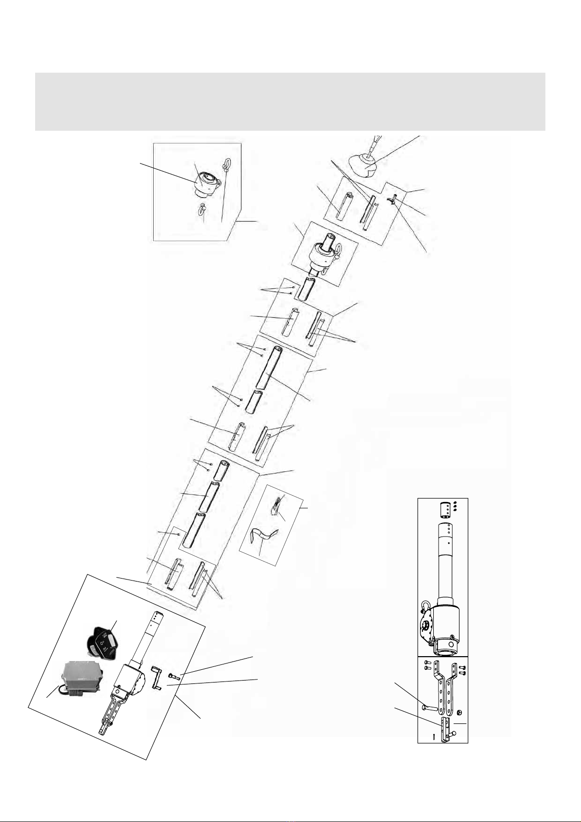
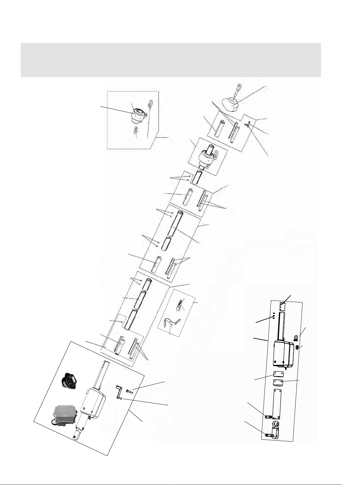
1. Monter provisoirement sans les gaines le kit de motorisation à la base de l’étai et/ou l’avale ridoir si cela est le cas.
avec l’enrouleur se montent correctement à la base de l’étai.
if any. This will ensure that: the height of the kit above the stem head chain plate suits your needs
2. Mesurer la distance entre le haut du kit de motorisation et l’extrémité du sertissage supérieur de l’étai, pour déterminer
la longueur des gaines.
2. Measure the distance between the top edge of the motorization kit or turnbuckle cylinder (if any) and the lower end
of the top swage terminal.
3. Re-démonter le kit et commencer le montage de l’enrouleur proprement dit.
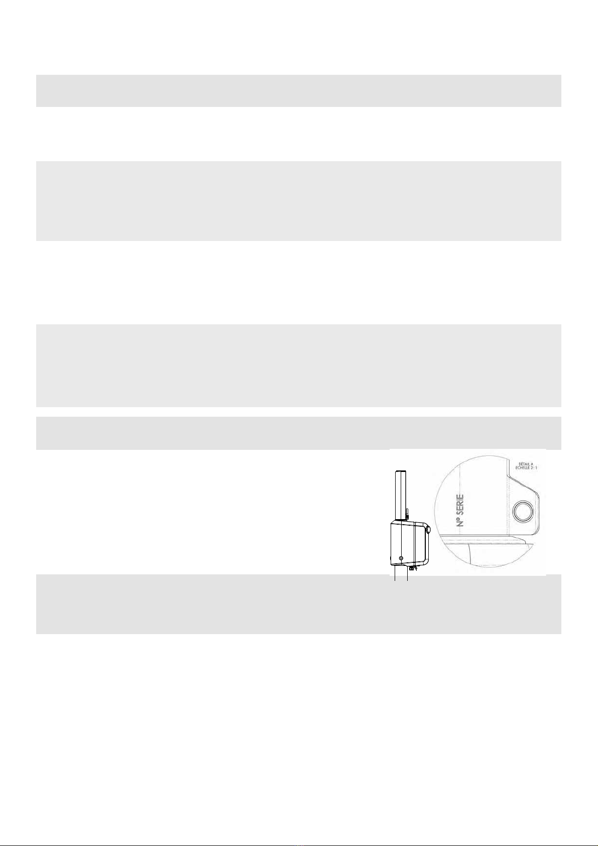
IDENTIFICATION DU SYSTEME / SYSTEM IDENTIFICATION
Each motorized system has a serial number located on integrated turnbuckle
(C420 etc...). In case of warranty claim, thanks to communicate this serial
number.
Seq.1