Enlarged
View
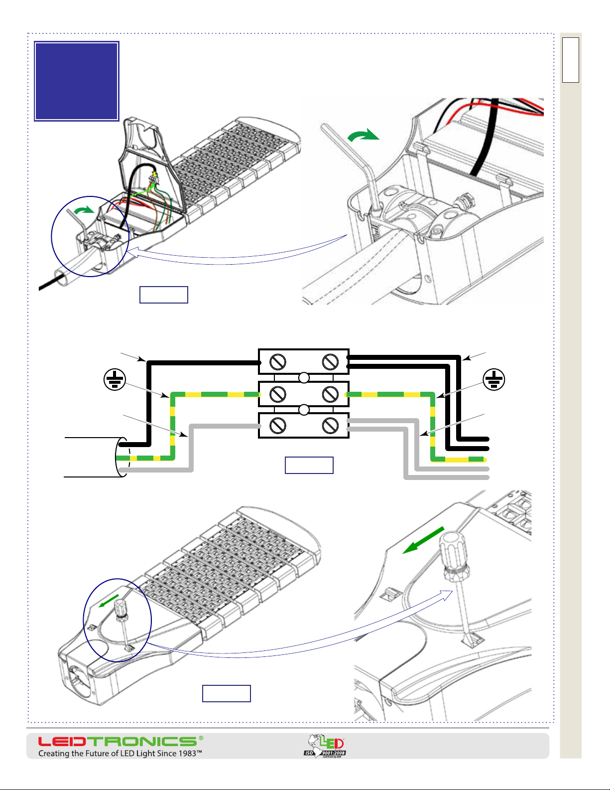
Figure 1
Figure 2
Power Box Cover
Ground
Wire
Power
Box Door
Latch
(Power Box
Door Latch
Inside Its
Slot Opening)
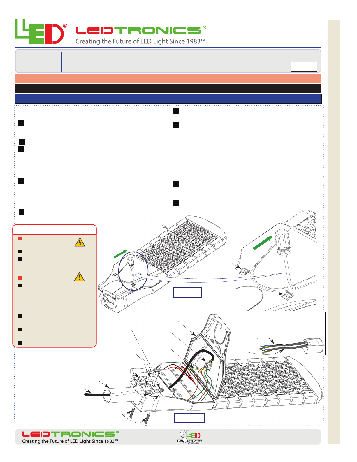
Power Input Cable
Support Arm Pole
6mm-Allen-Head Bolts (4 bolts)
(Clamps Receptacle)
5mm-Allen-Head Set Screws (2 screws)
(Locks Pole Arm to Receptacle)
Watertight
Connector
Wire
Connecting
Terminal
8mm-Allen-Head Bolts (2 bolts)
(Clamps Receptacle to Housing)
www.L E D troni c s .com
PACKAGE INCLUDES: LED Modular Luminaire with Mounting Screws + Installation Instructions
© 2014 LEDtronics, Inc.
23105 Kashiwa Court, Torrance, CA 90505
Phone: (800) 579.4875 / (310) 534.1505
Fax: (310) 534.1424
E-mail: info@ledtronics.com
Website: http://www.ledtronics.com
READ ANDFOLLOW ALL PRECAUTIONS AND INSTALLATION INSTRUCTIONS PRIOR TO INSTALLING THE LUMINAIRE
INSTR-SLM0XX-0001-E / 12/2014
Installation
Instructions
SLM0xx-xxxW-XXX-x01A3 Series
Modular Street/Area Lighting Luminaire, 120–277 VAC Page 1 of 4
Luminaire nal installation height from the ground should be no less than 13 feet [4 meters]
CAUTION –
RISK OF ELECTRIC SHOCK.
Suitable for wet or damp locations.
To prevent wiring damage or abrasion,
do not expose wiring to edges of sheet
metal or other sharp objects.
CAUTION – RISK OF FIRE.
This product must be installed in
accordance with the applicable
installation code by a person familiar
with the construction and operation of
the product and the hazards involved.
Consult a qualied electrician to ensure
correct branch circuit conductor.
Save these instructions and deliver
them to owner after installation.
No user-serviceable parts inside.
IMPORTANT SAFETY INSTRUCTIONS
Inspect the contents of the Luminaire packaging, and that they are free of
any damage that may have occurred in transit.
Determine Luminaire’s Mounting Conguration: (See last page):
Mount on a horizontal support arm pole; or mount at 90° to a vertical
pole*.
Ensure that all power is o before proceeding with wiring.
Opening power box door: Release the two latches that clamp the door
locked. Insert a large at-blade screwdriver between the latch and the
opening slot’s edge (Figure 1). Lever the handle in the direction of the arrow,
pushing the spring latch to click it o its locking position. Repeat for the
other latch.
Mounting to horizontal pole: Figure 2 and 3. (Holding receptacle is
precongured for horizontal mount. The two halves of the receptacle come
apart and are re-congured for right-angled vertical pole mount.*
Pass the power input cable from the support arm pole through the
Luminaire’s opening and through the watertight connector.
A
B
C
D
E
F
G
H
I
Insert and fasten the three wires into the wire connecting terminal
as shown in Figure 4.
The support arm pole is slipped into the Luminaire’s support arm
receptacle. With the receptacle’s halves bolted together**, tighten the
two set screws onto the pole.
Tilting the Luminaire option: Luminaire can be banked by rolling the support pole left
or right in the receptacle, then tightening the two 5mm-Allen set screws, xing the pole
to the receptacle.
Pitching the Luminaire up or down option: See Page 3. Unfasten the external
8mm-Allen-head bolts that clamp the adjusting receptacle (Figure 6). Adjust the
receptacle’s angle in the serrated holder (15° above to 15° below horizontal) till desired
(Figure 7). Tighten the 8mm bolts (Figure 8), securing pole to receptacle and housing.
Close the power box door: Avoid pinching the wiring. Setting the
latches to clamp door shut: Insert screwdriver (see Figure 5). Lever the
latch to snap into its clamping position. Repeat for the remaining latch.
Restore power.
*[90° Vertical pole mounting procedure, conguration,
pole size limits, TBD (To Be Determined)]
** The receptacle’s four
6mm-Allen-head bolts should be
tightened to 70.8 in-lbs [8 N-m]
torque.
SLM006-190W Luminaire with 6
modules depicted. Instructions
apply to 2 (SLM002) to 10
module (SLM010)
luminaires.
Optional Surge
Suppressor
(Remotely
Mounted)
Power In
Power
Out
Line: Brown = Black
Neutral: Blue = White
Ground: Green-Yellow