OPERATION MANUAL
9
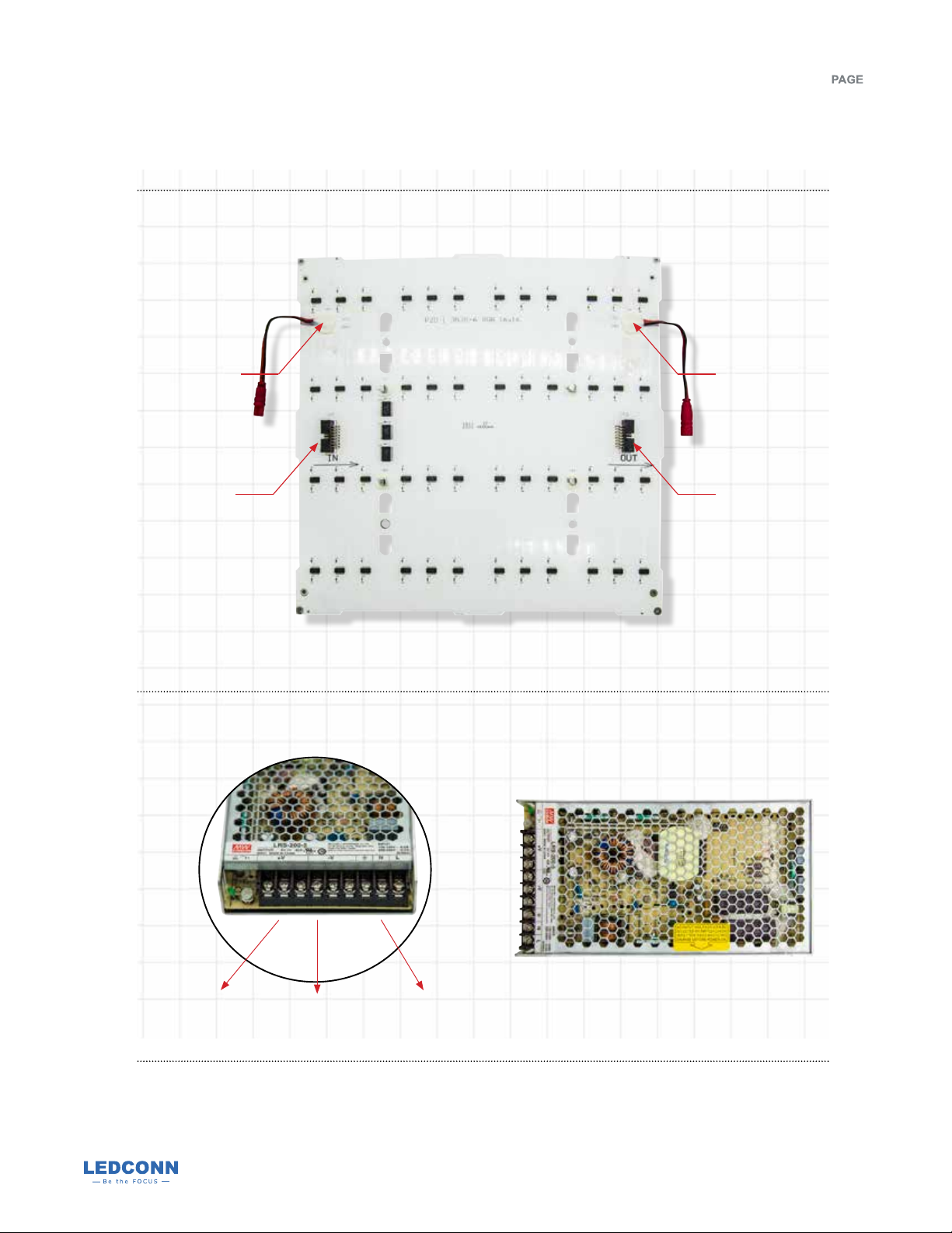
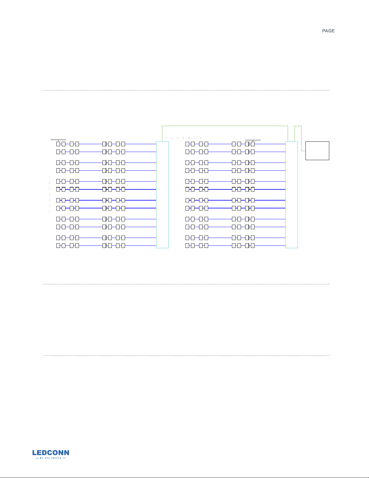
Data cable connection as shown below (blue for data cable and green for network cable).
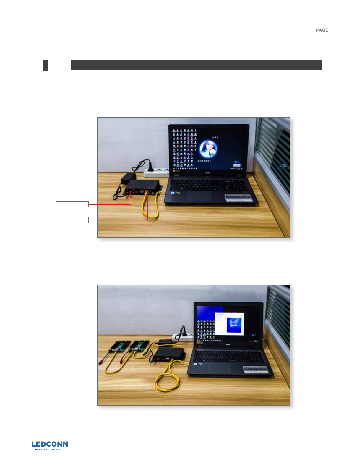
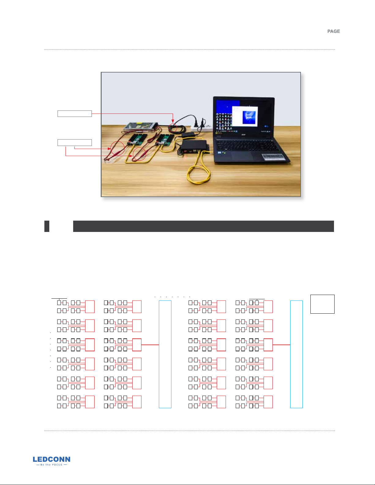
Connection method of data cable and network cable
Front of lightboxFront of lightbox
Row1 J1 J1
J2 J2
J11 J11
J12 J12
Column16
Control card 1
Control card 2
Column1
MC100
controller
Row12
Each receiving card has a total of 12 cable interfaces from J1 to J12, corresponding to each row of light
panels from top to bottom of lightbox (looking from the front of the light box). The right 8 columns of light
panels are controlled by the receiving card 1, and the left 8 columns of the light panels are controlled by
the receiving card 2. Total power of the light panels must be lower than the power output of the power
supply. Do not connect more than TWO pieces of light panels in series of each row. More details, please
refer to User Manual of MC100 (NF Series)
Note:
301 Thor Place, Brea, CA 92821 | tel (714) 256-2111 | fax (714) 256-2118 | sales@ledconn.com | www.ledconn.com
Specifications are subject to change without notice. © 2020 LEDCONN CORP. All Rights Reserved.
OM.20.01.R0
LUXDAZZLE™
Dynamic Motion Lighting
RGB