8
301 Thor Place, Brea, CA 92821 | tel (714) 256-2111 | fax (714) 256-2118 | sales@ledconn.com | www.ledconn.com
Details are subject to change without notice. © 2019 LEDCONN CORP. All Rights Reserved.
IG.20.01.R0
INSTALLATION GUIDE
SCAN FOR
DIGITAL VERSION
IMPORTANT SAFETY INSTRUCTIONS
Installation of this assembly requires a person familiar with the construction and operation of the luminaire's electrical system and the
hazards involved. If not qualified, do not attempt installation. Contact a qualified electrician If you are unfamiliar with methods for
installing electrical wiring, secure the services of a qualified electrician.
LEDCONN LED fixtures are designed to meet the latest NEC requirements and are listed in full compliance with the relevant UL
standard(s). Before attempting installation of any LED fixture, check your local electrical building code. All electrical connections must
be in accordance with local codes, ordinances and the National Electric Code. Always confirm that the maximum wattage of the flexible
sheet does not exceed the maximum wattage of the connected electrical circuit.
• IMPORTANT Risk of fire or electric shock. Installation of this
luminaire assembly requires a person familiar with the construction
and operation of the luminaires electrical system
and the hazard involved. If not qualified, do not attempt installation.
Contact a qualified electrician
• IMPORTANT Do not connect directly to AC power!
• IMPORTANT Risk of fire or electric shock. Install this assembly only
if the luminaires have the construction features and dimensions shown
in the photographs and/or drawings
•IMPORTANT To prevent wiring damage or abrasion, do not pinch or
damage expose wiring during installation. Keep away from to edges of
sheet metal or other sharp objects
• Verify power is off before installing or un-installing.
• Do not use product if any LED flexible sheet components are
damaged.
• The product has no user serviceable parts. Do not attempt to open
the product or repair it on site. If damaged, please notify LEDCONN
immediately for servicing.
• Do not exceed the specified voltage and current input (refer to the
specification sheet for power limitations).
• Do not hot plug the light engine to an energized power supply, hot
plugging may cause permanent damage to the LEDs.
• Avoid looking directly into the luminaire as the high brightness beam
may damage eyes.
• LEDCONN’s limited warranty applies only to LEDCONN's LUXFLEX
Standard, LUXFLEX Premium, and LUXFLEX RGBW.
• This product must be installed in accordance with the applicable
installation code by a person familiar with the construction and
operation of the product and the hazards involved.
• Do not make or alter any open holes in an enclosure of wiring or
electrical components during installation.
• Please retain these instructions for maintenance reference.
• Test before installing; LEDCONN products undergo rigorous
reliability testing before shipment, but due to unforeseen shipping and
handling issues inspect all flexible sheets to confirm receipt of good,
functioning luminaires.
WARRANTY
These handling and mounting materials and any other communications related to the installation of LUXFLEX LED flexible sheets are offered
for informational purposes only. Handling and mounting is the installer's responsibility. Under no circumstances is LEDCONN assuming any
liability, express or implied, regarding the installation or application of any of its LUXFLEX LED flexible sheets, whether proper or improper.
Further, LEDCONN assumes no liability for any costs associated with the installation or re-installation of LUXFLEX LED flexible sheets.
The standard warranty for this product is 5 years. Any damage caused by mishandling or improper installation of the product as outlined in
this installation guide will void the warranty. Examples of mishandling or improper use include but are not limited to: not cutting along product
cut lines; using power supplies or controls not recommended by LEDCONN; and using product in damp environments without proper damp
location treatment and installation. Please consult a LEDCONN team member for more information about the warranty coverage.
LIMITED
MANUFACTURER
WARRANTY
• LUXFLEX Standard and RGBW are provided by default with an IP54
rating that provides only partial protection against dust and water
splashing from all angles. Please avoid getting the product wet.
• Damp location rating (IP65) is provided for LUXFLEX Premium by
default with IP65. If your LUXFLEX Standard or RGBW product has
been custom requested with IP65 treatment, then it may also be
considered as a damp location product.
• Environmental factors will affect the type of IP rating required for
your applicaiton. If a custom IP Rating has been requested, please
consult with our engineering team for more specific information.
• Relative humidity should never exceed 70% MAX for indoor
applications.
STORAGE & MAINTENANCE
• For optimal LED performance, make sure LUXFLEX™ LED Flexible
Sheets do not exceed an operating temperature range of -4˚F min to
+140˚F max (-20˚C min to +60˚C max).
• For product without damp location treatment, store in a dry, clean
area.
• LUXFLEX may be cleaned, with the power off, by gently wiping with
a soft cloth, using care not to snag or harm the LED components.
• If LUXFLEX is dusty, turn the power off and apply compressed air to
clear any debris.
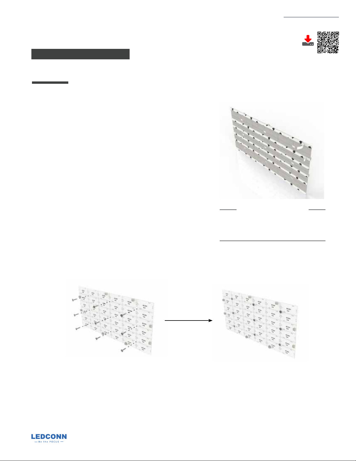
LUXFLEX™
Static White & RGBW
FLEXIBLE SHEET