LEEC SL2 User manual

1
OPERATING INSTRUCTIONS FOR
PLANTGROWTH INCUBATOR
MODELS SL2, SL3
WITH JUMO dTRON 316 CONTROL,
SMITH'S DIGITAL TIMERS &
TLK38 OVER & UNDER
TEMPERATURE CUT OUT.
PLEASE TAKE TIME TO READ THIS MANUAL
1.0 Incubator features
2.0 Installing your incubator & precautions
3.0 Initial set up procedure
4.0 Setting a single operating temperature
5.0 Setting two temperatures for dual temperature cycling
6.0 Lighting & timers
7.0 Humidity
8.0 Maintenance
Revised: June 2011
LEEC Limited
Private Road No.7
Colwick Industrial Estate
Nottingham
NG4 2AJ
Tel. 0115 961 6222
Fax. 0115 961 6680
http://www.leec.co.uk

2
1.0 INCUBATOR FEATURES
Your incubator is constructed from stainless steel and has high efficiency
polyurethane insulation. The refrigeration & electrical system is located in the
top housing underneath a removable lid. Inner glass doors allow you to view
the contents of your incubator without disturbing the internal atmosphere. The
chamber is sealed allowing water to be added to the base for keeping
products / samples in a high humidity environment. (See section 7.0 for more
details).
1.1 HEATING & COOLING SYSTEM
The unique LEEC temperature control system ensures exceptionally good
stability. A powerful refrigeration system provides cooling whilst low wattage
heaters provide heating. A door micro switch stops the internal fan(s) when
the door is opened to minimise temperature disturbance.
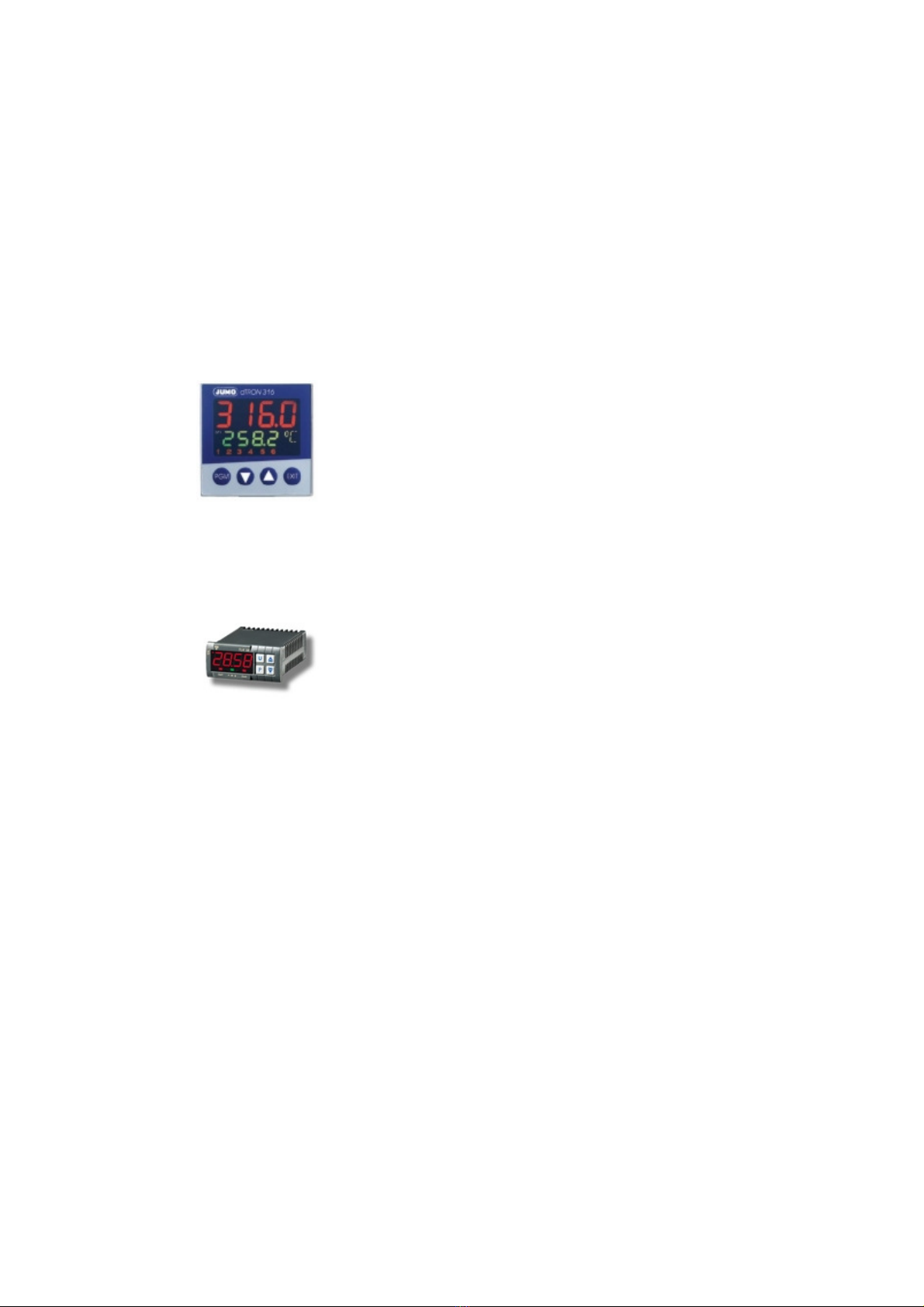
1.2 JUMO TEMPERATURE CONTROLLER
The temperature is accurately controlled by a Jumo dTRON
316 microprocessor controller that uses a signal from a
PT100 type sensor located in the chamber. Its purpose is to
control the cooling system and the current supplied to the
heaters. Operating temperatures can be programmed into
this controller electronically. Two set points (SP 1 & SP 2)
can be programmed which in turn allows the cabinet to cycle between two
different temperatures e.g. day & night, or operate constantly at one
temperature e.g. day.
1.3 TLK38 OVER & UNDER TEMPERATURE SAFETY CUT OUT
A TLK38 digital cut out protects the contents of your incubator. When the
chamber temperature goes out of limits, the appropriate cut out will operate
an audible alarm and visible red neon. Two reset buttons are provided below
the cut out for you to manually reset the offending system.
1.4 SMITH'S DIGITAL TEMPERATURE CYCLING TIMER
The light grey coloured Smiths digital 24 hour timer can be programmed with
several ON & OFF times for cycling between two pre-programmed
temperatures over a 24 hour period. The LCD display shows the current time
and cycle stage. The timer has an integral switch labeled ON, OFF & TIMED.
This switches between SP 1 & SP 2 temperatures, which are programmed
into the temperature controller. The switch positions correspond to:
ON - Incubator will operate constantly at the HIGH
(SP 1) temperate set point e.g. +37°C.
OFF - Incubator will operate permanently at the LOW
(SP 2) temperature set point e.g. +20°C.
TIMED - Incubator will cycle between HIGH & LOW (SP 1 &
SP 2) temperatures at the pre-programmed times.
ON & OFF times can be programmed into the timer as detailed in the
instructions at the back of this manual.

3
1.5 SMITH'S DIGITAL LIGHTING TIMER
A light grey coloured Smiths digital 24 hour timer, located on the incubators
control panel, controls the fluorescent lights in the outer door. Times can be
programmed into the unit. The LCD display shows the current time and cycle
stage.
The timer has an integral switch labelled ON, OFF & TIMED. The switch
positions correspond to:
ON - Lights are permanently ON.
OFF - Lights are permanently OFF.
TIMED - Lights will switch ON and OFF automatically at the
programmed times.
ON & OFF times can be programmed into the timer as detailed in the
instructions at the back of this manual.
2.0 INSTALLING YOUR INCUBATOR
Your incubator has a factory fitted UK style moulded plug. The wiring inside
the plug and mains flex is colour coded as follows: -
•BROWN = LIVE
•BLUE = NEUTRAL
•GREEN / YELLOW = EARTH
Your incubator requires a 240V 50Hz supply. An internal fuse provides
secondary protection.
2.1 REFRIGERATION PRECAUTIONS!
•Your incubator should be left to settle for 4 hours after final positioning
before it is switched for the first time to allow the refrigerant to settle.
•Do not place the cabinet in front of a window in direct sunlight.
•A qualified electrician or other competent person must carry out any
electrical work required to install this cabinet.
•Make sure that your incubator is not standing on its electrical cable.
•There are parts in your incubator that heat up. Always ensure there is
adequate ventilation, as failure to do so can result in component
failure.
•Keep all vent grilles clear.
•Before any cleaning or maintenance work is carried out, the mains
supply must be switched off and the plug removed from the socket.

4
3.0 INITIAL SET UP PROCEDURE
Switch the incubator on using the POWER switch located on the left hand
side of the control panel. The green neon inside the switch will illuminate if
the supply is connected correctly. If a warning buzzer sounds, press the reset
button to cancel it.
3.1 The COOLING switch will need to be ON.
3.2 The chamber circulating fan will only run when:
•The incubator is connected to the electrical supply,
•& the power switch is ON,
•& the outer door is closed.
3.3 TLK38 OVER & UNDER TEMPERATURE SAFETY CUT OUT
A TLK38 digital safety cut out unit provides essential over & under
temperature protection for the products inside the chamber. The cut out has
buttons labeled as follows:
P - Enters the programming mode.
U - No function.
▲- INCREASES the displayed value.
▼-DECREASES the displayed value.
3.4 SETTING AN OVER TEMPERATURE CUT OUT VALUE
If, for example, you would like to operate your incubator at +20.0°C, an over
temperature cut out value needs to be programmed into the cut out. We
recommend that the cut out value is set to 2 degrees higher than your
chamber temperature. In the example above, the over temperature cut out set
point needs to be set +22°C. To do this follow steps 1 - 3 below:
1) Press the P button once only. Flashing AL1 will be displayed plus a
value (the over temperature cut out value).
2) Press the ▲button to increase the over temperature cut out value
or the ▼button to decrease the over temperature cut out value.
3) Once the value of your choice is displayed, release all buttons and after
a short delay the new value will be stored and retained in permanent
memory.

5
3.5 SETTING AN UNDER TEMPERATURE CUT OUT VALUE
If, for example, you would like to operate your incubator at +20.0°C, an under
temperature cut out value needs to be programmed into the cut out. We
recommend that the cut out value is set to 2 degrees lower than your
chamber temperature. In the example above, the under temperature cut out
set point needs to be set +18°C. To do this follow steps 1 - 3 below:
1) Press the P button twice. Flashing AL2 will be displayed plus a value
(the under temperature cut out value).
2) Press the ▲button to increase the under temperature cut out value
or the ▼button to decrease the under temperature cut out value.
3) Once the value of your choice is displayed, release all buttons and after
a short delay the new value will be stored and retained in permanent
memory.
3.6 OVER & UNDER TEMP NEON’S, BUZZER & RESET BUTTONS
If the temperature in the incubators chamber goes above it’s upper set point,
the buzzer will sound and the over temperature neon will illuminate. The
heaters will automatically disconnect to prevent further over heating. The
buzzer & neon will remain on until a member of staff has acknowledged the
alarm. To reset the buzzer & alarm, press the reset button along side the
illuminated neon.
3.7 If the temperature in the incubators chamber drops below it’s lower set point,
the buzzer will sound and the under temperature neon will illuminate. The
refrigeration system will automatically disconnect to prevent further over
cooling. The buzzer & neon will remain on until a member of staff has
acknowledged the alarm. To reset the buzzer & alarm, press the reset button
along side the illuminated neon.

6
4.0 SETTING A SINGLE OPERATING TEMPERATURE
The Jumo 316 temperature controller on your incubator has a multi-function
LED display. The upper display (red) represents the actual chamber
temperature. The middle display (green) represents the target temperature.
The lower display (yellow) indicates when the controller is heating or cooling.
The yellow numbers on the temperature controller may be on, off or flashing.
They represent:
3- Heating
If the yellow 3 LED is off, heat is not being supplied to
the chamber. If the yellow 3 LED is on, heat is being
supplied to the chamber. If the yellow 3 LED is pulsing,
the target temperature has been reached and the
heaters are being pulsed to maintain a stable
temperature.
5 - Cooling
If the yellow 5 LED is off, cooling is not being supplied
to the chamber. If the yellow 5 LED is on, cooling is
being supplied to the chamber. The yellow 5 LED
should not pulse.
The Jumo 316 temperature controller has 4 buttons:
PGM - Program button (enters the engineering mode).
▲- Increases the chamber temperature.
▼- Decreases the chamber temperature.
EXIT - Exits the programming mode.
4.1 The controller also has two set points: SP1 & SP2 (Set Point 1 & Set Point 2).
When your incubator is to run constantly at one temperature, e.g. +37.0°C,
only a value for SP1 needs to be entered into the controller. To program
a single operating temperature, proceed as follows:
4.2 Make sure the Dual Temperature Cycling Timer slide switch is in the ON
position. This automatically selects SP1 on the temperature controller.
Then press either the ▲button to increase the chamber temperature or the
▼button to decrease the chamber temperature. The new value will be stored
automatically.
4.3 The incubator should now be programmed for +37.0°C, the over & under
temperature cut outs should be set and the cycling timer is programmed to
operate at the SP1 temperature only. Allow the chamber temperature to
stabilise before putting products in the incubator.

7
5.0 SETTING TWO TEMPERATURES FOR DUAL TEMPERATURE CYCLING
The Jumo 316 temperature controller on your incubator has a multi-function
LED display. The upper display (red) represents the actual chamber
temperature. The middle display (green) represents the target temperature.
The lower display (yellow) indicates when the controller is heating or cooling.
The yellow numbers on the temperature controller may be on, off or flashing.
They represent:
3- Heating
If the yellow 3 LED is off, heat is not being supplied to
the chamber. If the yellow 3 LED is on, heat is being
supplied to the chamber. If the yellow 3 LED is pulsing,
the target temperature has been reached and the
heaters are being pulsed to maintain a stable
temperature.
5 - Cooling
If the yellow 5 LED is off, cooling is not being supplied
to the chamber. If the yellow 5 LED is on, cooling is
being supplied to the chamber. The yellow 5 LED
should not pulse.
The Jumo 316 temperature controller has 4 buttons:
PGM - Program button (enters the engineering mode).
▲- Increases the chamber temperature.
▼- Decreases the chamber temperature.
EXIT - Exits the programming mode.
5.1 The controller also has two set points: SP1 & SP2 (Set Point 1 & Set Point 2).
When your incubator is to cycle between two temperatures, e.g. +37.0°C and
+20.0°C, SP1 & SP2 values need to be entered into the controller. To
program two operating temperatures, proceed as follows:
5.2 First you need to programme SP1. Make sure the Dual Temperature
Cycling Timer slide switch is in the ON position. This automatically
selects SP1 on the temperature controller. Then press either the ▲button
to increase the chamber temperature or the ▼button to decrease the
chamber temperature. The new value will be stored automatically.
5.3 Next you need to programme SP2. Make sure the Dual Temperature
Cycling Timer slide switch is in the OFF position. This automatically
selects SP2 on the temperature controller. Then press either the ▲button
to increase the chamber temperature or the ▼button to decrease the
chamber temperature. The new value will be stored automatically.

8
5.4 The Dual Temperature Cycling timer can now be programmed with several
ON & OFF times for cycling between two pre-programmed temperatures over
a 24 hour cycle. The LCD display shows the current time and cycle stage.
The timer has a slide switch labelled ON, OFF & TIMED. It interacts with the
temperatures that are programmed as SP1 & SP2 on the temperature
controller. The switch positions correspond to:
ON - Incubator will operate constantly at the HIGH
(SP1) temperate set point e.g. +37.0°C.
OFF - Incubator will operate permanently at the LOW
(SP2) temperature set point e.g. +20.0°C.
TIMED - Incubator cycles between HIGH & LOW (SP1 &
SP2) temperatures at the programmed times.
To cycle automatically between the two temperatures at the pre-
programmed times, move the slide switch to the TIMED position.
The incubator should now be programmed for +37.0°C and 20°C, the over &
under temperature cut outs should be set and the cycling timer is
programmed to cycle between the SP1 & SP2 temperatures. Allow the
chamber temperature to stabilise before putting products in the incubator.
6.0 LIGHTING
6.1 SMITH'S DIGITAL LIGHTING TIMER
A light grey coloured Smiths digital timer, located on the right of the
incubators control panel, controls the fluorescent lights in the outer door.
Times can be programmed into the unit. The LCD display shows the current
time and cycle stage.
The timer has an integral switch labelled on, off & timed. The switch positions
correspond to:
ON - Lights are permanently on.
OFF - Lights are permanently off.
TIMED - Lights will switch on and off automatically at the
programmed times.
6.2 Near the lighting timer, you will find a bank of switches. These switches allow
individual fluorescent tubes to be switched permanently off. If for example, a
lower lighting intensity is required. One or more switches can be switched off.
One switch is provided for each fluorescent tube.
6.3 If lighting is required, ensure that these switches are ON, otherwise the tubes
will fail to illuminate automatically when the lighting timer calls for ‘lights on’.
6.4 Program the ON & OFF times into the timer as detailed in the instructions at
the back of this manual.

9
7.0 HUMIDITY
7.1 A wide range of fixed relative humidities can be achieved by adding suitable
saturated salt solutions (or just water) directly into the base of the chamber.
The relative humidity of air in contact with saturated salt solutions reaches
known equilibrium values at certain temperatures.
Salts Graph
7.2 The graph above shows the temperatures and relative humidities for several
of the more common saturated salts. The distilled water/saturated salt
solution should be topped up regularly and should fully cover the floor at all
times. Do not allow the water/saturated salt solution to evaporate or the
humidity control will be affected.
7.3 Allow the chamber temperature and humidity to stabilise before placing
products inside the chamber.
8.0 MAINTENANCE
The chamber should be defrosted if there is a build up of ice in the air duct as
this will restrict the airflow and affect the incubators performance. To do this,
either raise the operating temperature of the incubator to +40°C for several
hours, or switch the cabinet off completely and leave the outer door open
over night
8.1 Regular cleaning & de-fluffing of the condenser is recommended. Keep all
ventilation grilles clear & unrestricted. The inner chamber & exterior of your
incubator can be cleaned with a damp cloth and a mild detergent solution.
8.2 In the event of spillage of hazardous materials use the appropriate
decontamination method as prescribed by the HSE or local Safety Officer.
This manual suits for next models
1
Table of contents
Other LEEC Accessories manuals