4
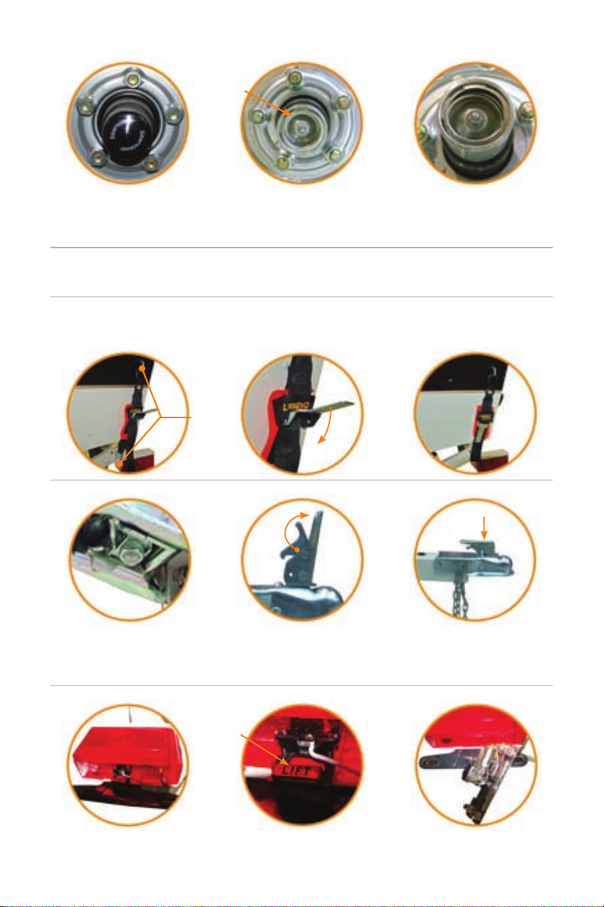
ADJUSTING YOUR COUPLER:
Reach under the coupler and
raise the channel lock up. Turn the
adjusting nut clockwise to tighten and
counterclockwise to loosen ball clamp
grip on the ball.
Replace the hitch back on the ball
and latch. Repeat this process
until the ball clamp latches
securely around the ball.
Remember tightening the coupler
does not compensate for 2”- 17/8”
ball. Be sure your ball matches your
coupler every time. Legend trailers
use only 2” ball couplers.
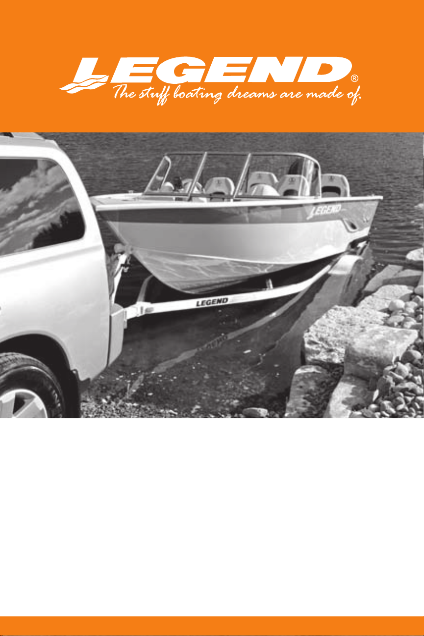
If the piston cannot be moved, it’s
time to add grease. Use a hand
operated grease gun and add
only enough to move the piston
outward until it rocks.
Bearing buddies create a positive
pressure inside the hub. Because
of this constant internal pressure
inside the hub, water cannot enter.
To check the hub lubricant level,
press on the edge of the spring
loaded piston. If you can move
or rock the piston, the hub has
sucient grease.
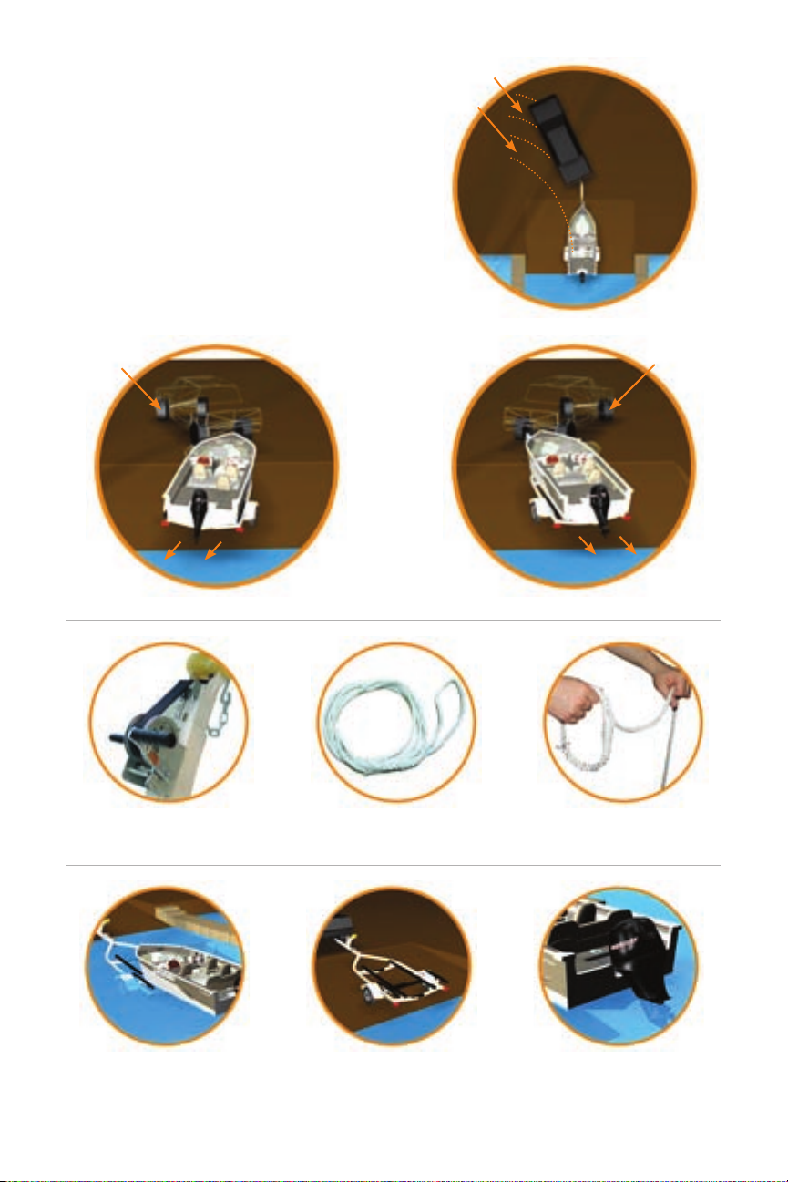
TIE DOWNS:
Your boat must be properly supported by the trailer. Your boat must also stay positioned on the trailer while
towing. This is accomplished by securing the boat to the trailer with tie downs. The black rubber coated
hook goes on the boat, and the metal one on the trailer. Do not over tighten.
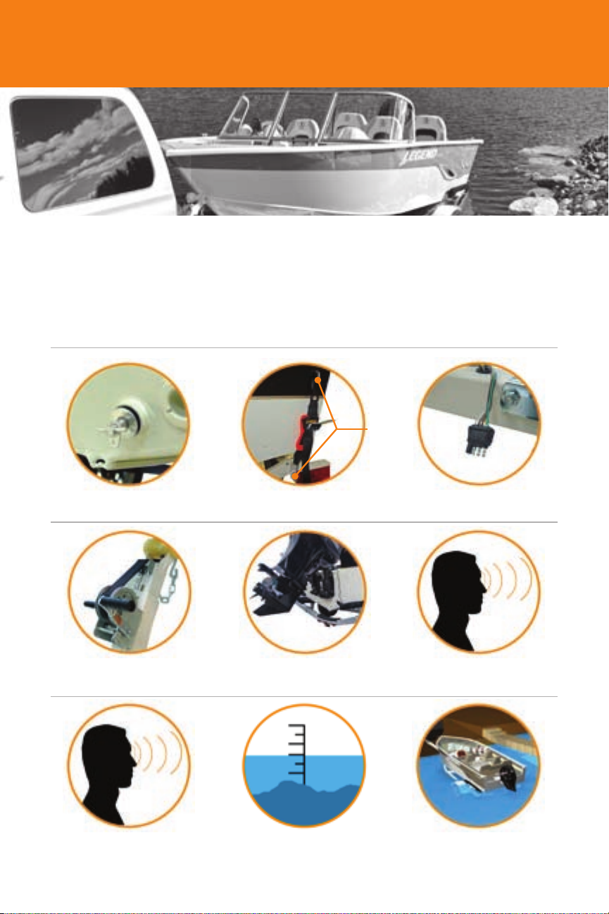
Locate the plastic tab
underneath the tail light
Note: Larger trailers have two screws that are to be removed for tail light replacement.
Simply lift on the tab or
unscrew both screws
The entire wiring harness assembly will
drop and hang for easy bulb replacement.
Hook
Press here
Lift tab
INSPECTION:
Ensure to inspect lights and tighten wheel nuts and all trailer bolts after the rst 100 miles and
then every 300 miles for safety.
BEARING BUDDIES:
REPLACING YOUR TAIL LIGHT: