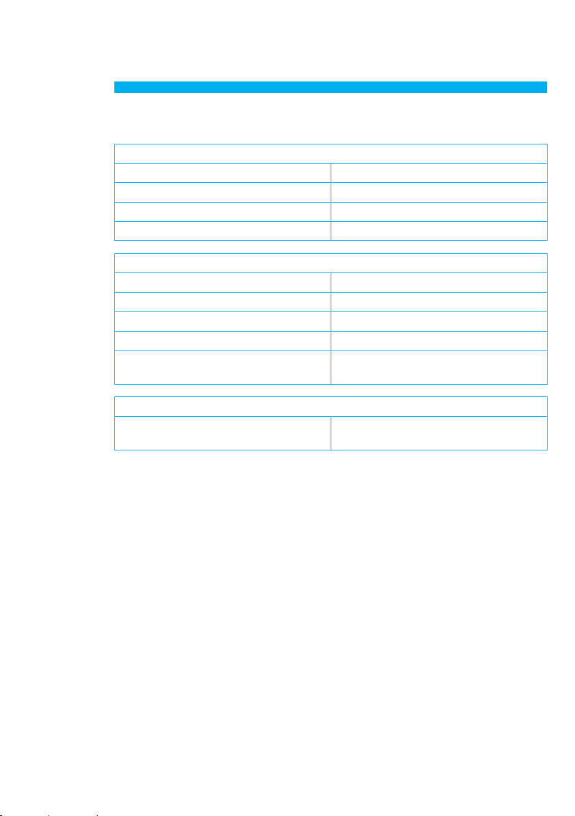
4 - Éventuels problèmes et solutions
PROBLÈME CAUSE SOLUTION
Le voyant ON/OFF (indicateur
d’état) ne s’allume pas
Alimentateur installation en
protection.
Contrôler et éliminer la cause du
court-circuit.
Charger l’alimentateur.
Absence de tension 27 Vdc sur la
borne BUS de l’alimentateur.
S’assurer de la présence de tension
24 – 27 Vdc sur la sortie OUT du
nœud A/V de connexion. En cas
d’absence de tension, éliminer le
court-circuit du BUS sur le côté du
nœud A/V
Le système Hi-Fi n’est pas
commandé via IR Mauvais branchement du câble IR.
Contrôler et corriger le câblage:
le câble à émetteur IR doit se
trouver à 1 cm du récepteur IR du
système Hi-Fi à contrôler.
Quand le système Hi-Fi est allumé,
le voyant ADJ reste éteint.
Signal audio absent. S’assurer de la présence du
signal audio.
Signal audio très faible.
Contrôler le réglage du poten-
tiomètre d’adaptation du niveau
ou augmenter le niveau du signal
fourni par la source externe.
Le voyant de niveau reste rouge. Procéder au réglage du poten-
tiomètre d’adaptation du niveau.
Distorsion du signal reproduit y
compris à faible volume.
S’assurer que le voyant de niveau
ne devient pas orange durant la
reproduction des morceaux. Régler
le potentiomètre du système Hi-Fi
allumé de telle sorte que le voyant
soit toujours vert (seuls de brefs
allumages de couleur orange sont
admis lors des pics musicaux).