LEGRAND 430 557 User manual

Manuale di istruzioni
User manual
430 558 - 430 559
MANUEL D’UTILISATION
USER MANUAL
430 557
LE03716AA
• Enregistreur LAN 500 Gb 4/8/16 caméras avec gestion centralisée sur PC
• 4/8/16-camera 500 GB LAN recorder with centralized management on PC
• Grabador LAN 500 Gb 4/8/16 cámaras con gestión centralizada en PC
• Gravador LAN 500 Gb 4 câmaras com gestão centralizada por PC
•Rejestrator LAN 500 GB, 4 kamery, z zarządzaniem scentralizowanym na PC
430 557/558/559

CHAPTER 1 Software installation ........................................................... 3
CHAPTER 2 Display Mode ....................................................................... 4
CHAPTER 3 CMS Setup Mode................................................................. 16
DVR Remote Setup.............................................................. 30
CHAPTER 4 Remote Search Mode.......................................................... 37
CHAPTER 5 E-Map Mode ......................................................................... 47
CHAPTER 6 Remote Update.................................................................... 67
CONTENTS
2

Chapter 1 Software installation
Compatible operating systems: Windows 2000, XP, VISTA.
Please insert the CD-Rom included in the DVR box.•
Go to Program / CMS folder.•
Start CMS software installation:•
Chose your language•
Chose the style of screen display•
The software is installed on your PC:•
All the datas related to this software are stored in following folder: C:\CMS_2KV3•
Following icon will be installed on your desktop:•
CMS software, to manage remotely several DVR
3

Chapter 2 - Display Mode
4

Login•
Click on “ start “, and “ Log in “.•
Enter User name and Password:•
Default User ID : administrator
Default password : 1234
Ask administrator or Bticino customer support if you forgot ID or password.
5

User Interface•
Search : search saved image on local or network drives.
Setup : setup on CMS system.
E-Map : Monitor DVR sites, Camera, Sensor, and Control through E-
MAP.
Log Viewer : can check or print ‘Log file’ in the CMS system.
Log out : Log in/out
Start : can execute overall CMS functions such as log in/out, Setup,
Search.
6

Display screen•
#1 [CAM01] :• It represents DVR name, screen number, and camera name.
R :• “R” is present if this image is saved on CMS software.
• : this image is with audio data.
C 10-12 16:30:14 :• It represents the date and time of transmitted data.
“10-12 16:30:14” DVR System time
• :E-Map : Click this button to enable ‘E-MAP’.
• Print: Click the button to print the image.
Snapshot: Click the button to save the appropriated image.
(Location for saving - C:\CMS_2KV3\Image)
Screen Switch on Display mode :• put the mouse on the screen, and click right mouse button
and drag to the desired screen to display.
¢—E-Map, Print, Snapshot button shown on one division screen.
E-Map, Print, Snapshot button shown on one division screen.
7

How to switch from multi screens to one screen?•
Double click on one image:
It will show the selected screen:•
Double click on the screen will switch back to multi screens.•
Right click on the
image will
enlarge it
back to multi screens.
8

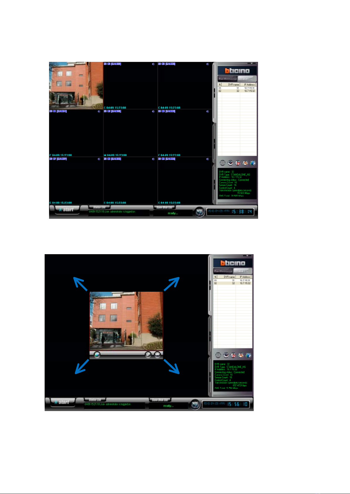
- Click ICON of PTZ as the left image.
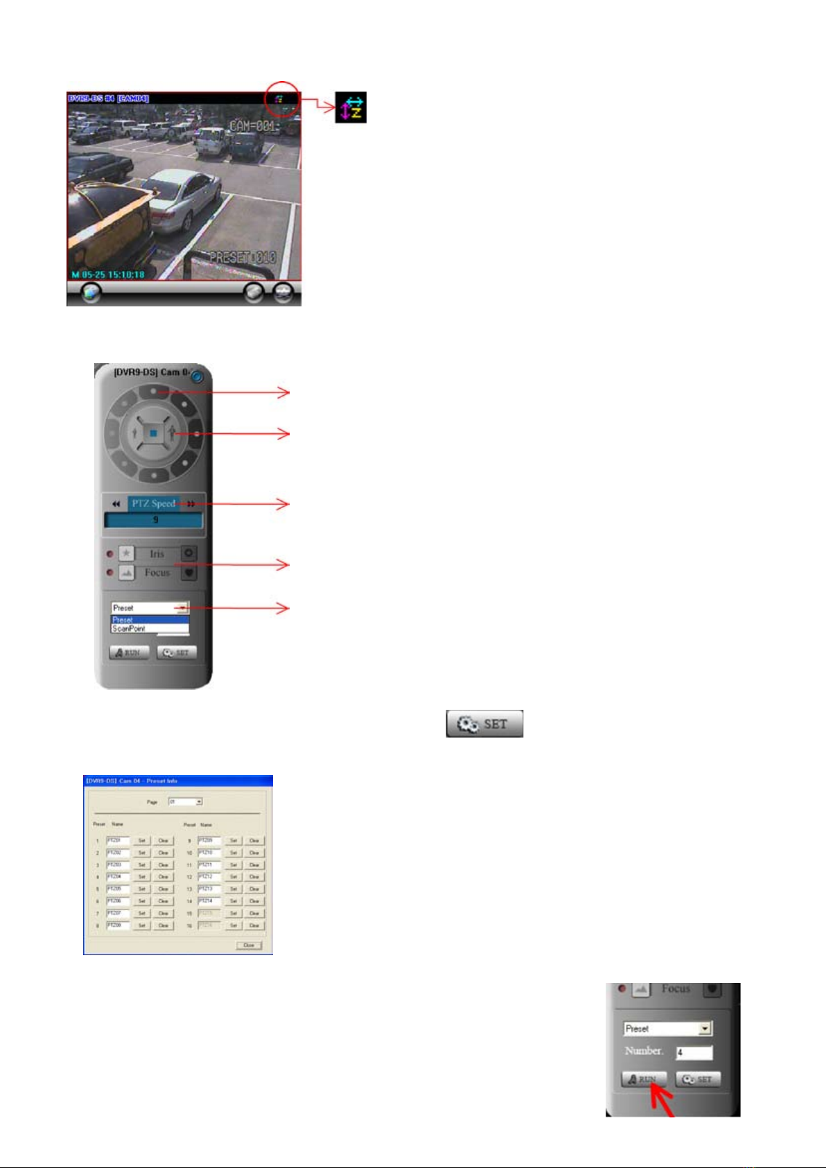
Can control up , down, left & right direction of PTZ.
Can Zoom IN / OUT of PTZ.
Can control speed of Zoom IN & OUT & its Movement of PTZ.
Can control Iris, Focus of PTZ..
Can use the function of Preset/Scan point for PTZ.
- Preset Setting: after selecting Preset, click SET button.
User move PTZ on the direction of up, down, left & right,
with Zoom In & Out to the position which user want to move, and then click
Set Button.
Preset setting can be available up to 64 times.
- Preset Operation: input the preset number, and click on “RUN” button.
PTZ Controller : can control• PTZ from the remote site of CMS via network
9

- ScanPoint Setting:
This function will allow you to switch from one Preset position to another. For example:
Preset 1 Preset 2 Preset 3
(5 secondes) (3 secondes) (4 secondes)
- after selecting ScanPoint , click SET Button:
According to the order of the left image menu,
select Preset number & duration time.
ScanPoint can be set up to 4 times per camera.
- ScanPoint Operation: : input the scanpoint number, and click on ‘RUN’ button:
10

Connection list & sensor/control & screen division•
Connection list•
There are two ways which are ‘Pre-Memorize’
and ‘DVR list’ on the connection list.
Pre-Memorize:•
Shows the video for each page, previously customized (several DVR).
DVR list:•
Shows the video for each page of one DVR.
Example Pre-Memorize DVR list
DVR 1
Camera 2
DVR 2
Camera 8
DVR 3
Camera 5
DVR 4
Camera 2
Page 1
DVR 8
Camera 3
DVR 6
Camera 1
DVR 7
Camera 4
DVR 4
Camera 5
Page 2
DVR 1
Camera 1
DVR 1
Camera 2
DVR 1
Camera 3
DVR 1
Camera 4
Page 1
DVR 2
Camera 1
DVR 2
Camera 2
DVR 2
Camera 3
DVR 2
Camera 4
Page 2
11

DVR list•
Monitor all cameras of each DVR .
Single / Multiple Mode• : Click the button to activate single or multiple mode
as pre memorize access.
Connection• : Click the button to connect or disconnect to DVR.
Remote Setup• : Click the button to use remote setup for selected DVR.
Remote Search• : Click the button to use remote search for selected DVR
E-map• : Click the button to use E-MAP for selected DVR.
Status• : It represents the information and the status of accessed DVR.
Single Mode / Multiple Mode :
This button is useful only when you use ‘Pre-Memorise’ list:
- Select ‘Pre-Memorise’ list, and chose a customized page
- Connect the stream: click on
- When you want to switch to one DVR:
Select the DVR
And click on
12

The button will switch automaticaly to :
If you want to switch back to ‘Pre-Memorize’ screen, click on button.
13

Sensor/Control
- Select the registered DVR name, then, click each button of sensor and control
to activate.
Click on the arrow to view this menu.
Screen division
- Various surveillance modes available through division buttons
Click on the arrow to view this menu.
Status•
Status list•
It represents the event messages of CMS program.•
Status list : click the button to check the details of event message.
14

Save Disk List : Select the drive to setup save disk for the data from each DVR.•
Save Disk List : Free space and status of each drive can be checked.
2WAY AUDIO: Audio communication between CMS and DVR available.•
Click ‘AUDIO CHAT’ button on CMS, and select DVR name to talk, then, click ‘Talk’ button to send
Request to DVR site:• Audio chat button will be flashed on/off on DVR by requesting audio communication from
CMS.
Save Disk List : Free space and status of each drive can be checked.
Setup the port for 2way audio communication. Control the setup and volume of microphone by volume button.•
Digital-Clock:• It represents the date of CMS system. Display format can be changed.
15

Chapter 3 - CMS - Setup Mode
To enter in this menu•
Click on ‘start’•
Click on ‘Setup’•
16

Setup•
USER :• make the user group with different privilege. Default is ‘ADMINISTRATOR’.
Registered user list• : It represents the group of registered users.
Register new user• : Register new user : click this button to add new user, and click ‘Apply’.
Privilege• : you can assign different privilege to each user.
My image• : change the image with that you prefer such as company logo.
17

DVR Setup :• how to add a new DVR
DVR name: has to be the same as registered in the DVR (see menu NETWORK – CLIENT of the DVR)•
DVR info: put STANDALONE DVR_NS•
Data/stream ports: have to be in line with ports declared on the DVR•
(see menu NETWORK – CLIENT of the DVR)
Click on :
Add DVR
Fill the
information
and click on
OK
18

DVR Setup :• information you will find for all registered DVR
Registered DVR list• : represents all registered DVR.
IP address of my computer• : represents IP address of the computer.
DVR Info• : shows the information of Network connection as DVR is registered.
19

Delete• : click it to remove the registered DVR.
Edit DVR• : edit setup information. You can make changes (ex: IP address), and then click on ‘Edit DVR’ to save
changes.
Conn. Setting• : it is for modem connection setup. You should setup ‘Modem’ on OS, click on ‘Edit DVR’, and this
button will be enabled. Adjust the time for retrying connection. If there is no response from the site system, the
system will retry connection as you set up.
Name I/O :• you can change the name of sensor and control.
Double click ‘Enter name’, and it will be enabled to put the name.
20
Other manuals for 430 557
2
This manual suits for next models
2
Table of contents
Other LEGRAND DVR manuals