LEGRAND 4 306 60 User manual

USER MANUAL
LE04761AA
• IP modular camera D1
4 306 60

2
Indice
1 Accessories ........................................................................................................................... 4
2 General Introduction ................................................................................................................ 5
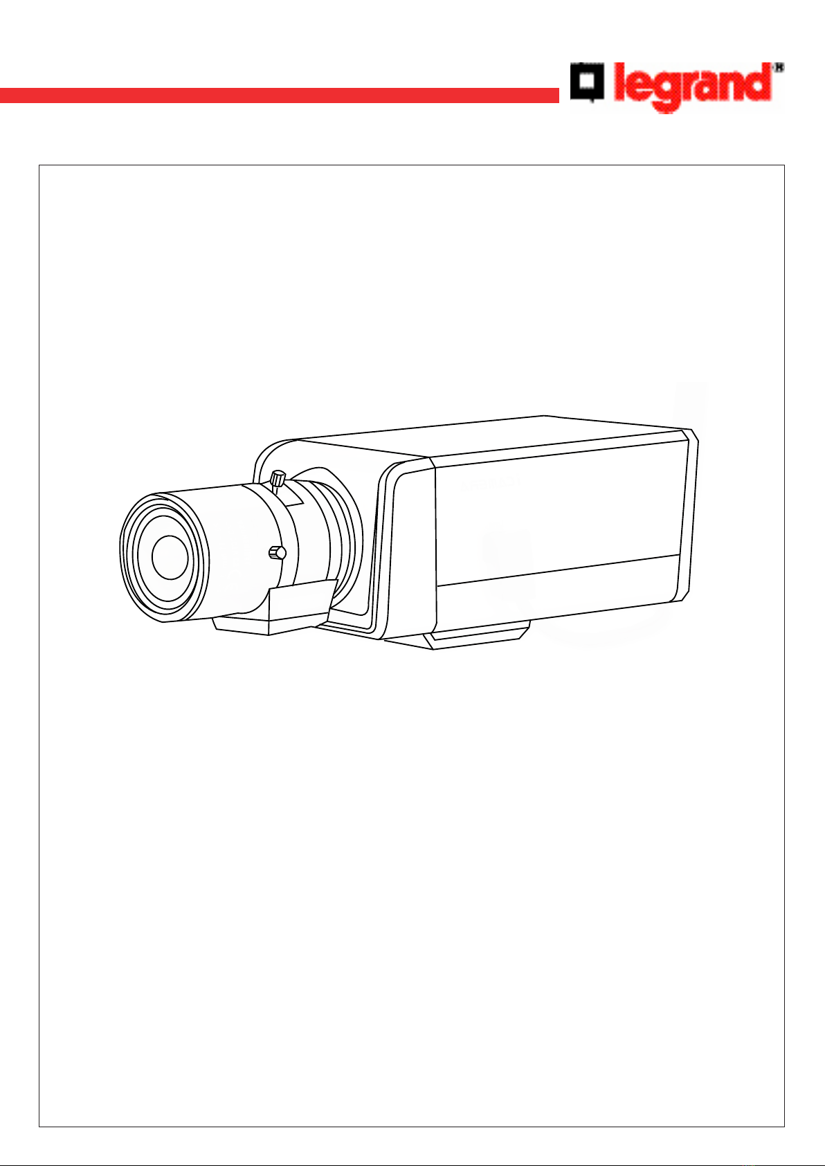
2.1 Overview ........................................................................................................................................ 5
2.2 Features ........................................................................................................................................ 5
2.3 Specications ...................................................................................................................................... 6
3 Framework ........................................................................................................................... 13
3.1 Rear Panel ........................................................................................................................................ 13
3.2 Side Panel ........................................................................................................................................ 15
3.3 Front panel ........................................................................................................................................ 15
4 Installation ........................................................................................................................... 16
4.1 Lens Installation .............................................................................................................................. 16
5 Quick Conguration Tool ........................................................................................................................ 19
5.1First Connection .................................................................................................................................. 19
6 Connecting to a Device and Opening the Web Application ............................................................. 27
6.1PC Conguration ................................................................................................................................. 27
6.2Connection with the Search Tool ..................................................................................................... 28
6.3Connection with Internet Explorer.................................................................................................. 29
6.4Login ........................................................................................................................................ 29
7 Main Interface Introduction ................................................................................................................... 31
7.1 Log in ........................................................................................................................................ 31
7.2 Monitor Channel Menu Tree .......................................................................................................... 32
7.3 System Menu ....................................................................................................................................... 33
7.4 Monitor Window Switch .................................................................................................................... 34
7.5 Preview Window Switch .................................................................................................................... 34
7.6 PTZ Control ........................................................................................................................................ 34
7.7 Color and More Setup........................................................................................................................ 34

3
8 Congure ........................................................................................................................... 36
8.1 System Information ...............................................................................................................................................36
8.2 System Conguration ...........................................................................................................................................38
8.3 Advanced ........................................................................................................................................................54
8.4 Additional Function...............................................................................................................................................59
9 Search ........................................................................................................................... 63
10 Alarm ........................................................................................................................... 65
11 About ........................................................................................................................... 66
12 Log out ........................................................................................................................... 67
Annex 1: No-IP DDNS .................................................................................................................................... 68
Annex 2: Using Google Chrome .................................................................................................................. 74
Annex 3: Using Firefox .................................................................................................................................. 76
Annex 4: Using IE8 ........................................................................................................................................ 78
Annex 5: Email Function ............................................................................................................................... 81
Annex 6: Routers conguration .................................................................................................................. 84

4
1 Accessories
Name Qty
IP Camera 1
12V power adapter 1
Quick Start Guide 1
CD 1

5
2 General Introduction
2.1 Overview
This device integrates traditional camera and network video technology. It adopts audio video data collection, transmission
and storage. It can connect to the network directly without any auxiliary device.
This device uses standard H.264 video compression technology which maximally guarantees the video quality.
It can be used alone or used in a network area. When it is used lonely, it can be connected to the network and used from
a network client-end.
2.2 Features
User Management Dierent user rights for each group, one user belongs to one group.
The user right shall not exceed the group right.
Data Transmission Support cable network data transmission via Ethernet.
Storage Function
Support central server backup function in accordance with conguration and setup
in alarm or schedule setting.
Support record via Web and the recorded le are stored in the client-end PC.
Support local SD card hot swap.
Alarm Function
Real-time respond to local alarm input and video detection as user pre-dened
activation setup and exert audio prompt(allow user to pre-record audio le).
Realize real-time video detect such as motion detect, camera masking and video
loss.
Network Monitor
Supports one-channel audio/video data transmit to network terminal
Max supports 10 connections.
Adopt the following audio and video transmission protocol: HTTP, TCP, UDP, MULTI-
CAST, RTP/RTCP and etc.
Support web access.
Network Management
Conguration and management via Ethernet.
Support device management via web.
Support various network protocols.
Peripheral Equipment Support peripheral equipment connection via the RS232 port.
Support serial port (RS232/RS485) transparent data transmission.
Power External power adapter. Support DC 12V.
PoE
Support Power over Ethernet (PoE). Conform to the IEEE802.3af standard.
Connect the device to the switch or the router that supports PoE function to realize
the network power supply.
To guarantee proper performance, make sure the power source can supply at least
6,4W power.
Assistant Function
Day/Night mode auto switch.
Support system resource information and running status real-time display.
Support log function.
Support video watermark function.

6
2.3 Specications
2.3.1 Performances
Model
Parameter
Ref. 4 306 60
Camera
Sensor Type 1/3-inch SONY Supper HAD CCD
Pixel PAL: 795 (H) x 596 (V)
Lens Mode CS mount
Video format PAL
Shutter 1/50 - 1/10000s
Min. Illumination 0.1Lux/F1.2
Auto Iris DC Iris
Analog Output BNC
SNR > 50dB
Video
Standard PAL: 1f/s ~ 25f/s
Encode Capability H.264
Encode Bit Stream D1 (704 * 576 /704 * 480)
HD1 (352 * 576 / 352* 480)
CIF (352 * 288 / 352 * 240)
QCIF (176 * 144 / 176 * 128)
Video Recording Speed PAL: 1-ch 1f/s ~ 25f/s adjustable
Network Capacity Max support 10 network users to monitor simultaneously
Power Consumption < 5W
Power DC 12V or PoE
Temperature - 10°C ~ + 55°C
Working Environment Humidity 10% ~ 90%
Dimension (H * W * D) 141,4 mm * 141,4 mm * 111,5 mm

7
2.3.2 Function specication
Specications Note
CCD Video Process
Backlight compensation control Auto
White balance adjustment N/A
Contrast ness adjustment Auto
Bright ness adjustment Auto
Electronic shutter control Auto
Color/B&W(Day/Night) switch
Auto
Note:
The color/B&W (Day/Night) switch here just an
electronic switch. System removes the color
elements and reserves the B&W elements. It is not a
lter switch.
Video
Resolution D1/HD1/CIF/QCIF
Video compression Standard H.264 encode/decode format
Motion Detection
Take 18 * 22 pix as a macro unit
Support 396 detection zones
Sensitivity level ranges from 1 to 6
Dual-stream 1-channal real-time D1 + 1-channel CIF
Audio Bidirectional Talk Bidirectional talk. Delay within 200ms
Audio Listening Audio listening. 1-ch MIC input
Network
WEB access via IE browser
PPPoE dial function
DHCP auto get IP address
DDNS
SMTP email function
NTP time synchronization
DNS domain parse
IP address lter
Record
Schedule Record Support max 6 periods
(This series product does not support this function.)
Manual Record
After enabling manual record, no matter system is in
schedule or alarm status or not, system just begins
recording
Alarm Record System automatically enables recording function
when alarm occurred
Motion Detection Record When video changes, system automatically enables
record operation
OSD
Time Title Display
There are 255 layers
- is the bottom layer and 255 is the highest layer
- means completely transparent and 255 is opaque
Channel Title Display Please refer to the above information
Privacy Mask Max supports 8 zones

8
Specications Note
Storage
Local Micro SD storage Support high-speed card/low-speed card
Based on SDK network storage Supported
Alarm
Network alarm/local alarm
output 1-ch local/network alarm output
Local alarm/network alarm input 2-ch local/network alarm input
Event Management
Activate alarm via motion
detection or external input
Please enable pre-record function when activating
the alarm
Upload image email. Upload automatically
Send out alarm notice via email,
HTTP and external port. Support de-jitter when alarm occurs frequently
Support video short time buer
storage before or after alarm Pre-record is 2Mbytes. Buer storage video of 5s
Control RS485 PTZ control Support semi-duplex communication way
On-line Upgrade Network remote upgrade Use upgrade tool
Device Management Network client-end Log in the client-end software in the PC to monitor IPC
Parameter Conguration
IPC provides device information, video information, COM setup, record setup, motion
detection setup, alarm setup, OSD information interfaces to modify system setup
IPC provides running information such as user port, log, status, user management, email
setup, date modication
Log
System can record the important event log record
Record the following information:
System operation, setup operation, alarm event, record management, user
management, clear log
Water Mark To avoid vicious video modication
Power supply DC12V power supply

9
2.3.3 Factory Default Setup
Please refer to the following sheet for factory default setup information.
Function conguration type Item Name Default setup
General Setup
Date format Y-M-D
DST Disable by default
Date separator ‘ _ ’
Time format 24H
Language English
When HDD is full Overwrite
Record duration 60 min
Device No. 8
Video type PAL
Encode Setup
Main stream
Channel Channel01
Compression H.264
Enable audio and video
General bit stream Main stream
Resolution D1
Frame rate 25
Bit stream control CBR
Bit stream value 2048
I frame interval control 50
Extra stream
Extension stream Main stream
Audio/Video enable Enable audio and video
Resolution CIF
Frame rate 25
Bit stream control VBR
Quality Hight
Bit stream value 512
I frame interval control 50
Image color
Brightness: 50
Contrast: 50
Saturation: 50
Hue: 50
Watermark
Enable
Stream type: all
Type: Character
Character: Digital CCT
Privacy Mask Never
Time title Enable. OSD transparent (read-only):0
Channel title Enable. OSD transparent (read-only):0
Schedule setup
Channel Ch01
Pre-record 5 seconds
Time Setup
Start time 0:00:00
End-time 23:59:59
Record Period 1 : Enable motion detection/
alarm

10
Function conguration type Item Name Default setup
Schedule setup Time Setup Snapshot Period 1 : Enable motion detection/
alarm
Week Sunday
RS232 Setup
Option COM01
Function Console
Data bit 8
Stop bit 1
Baud rate 115200
Parity None
Network setup
Ethernet Port 01
DHCP Disable
IP address 192.168.1.108
Subnet mask 255.255.0.0
Gateway 192.168.0.1
Device name Device factory default name
TCP port 37777
HTTP port 80
UDP port 37778
Max connection 10
Network transmission QoS Disable
Remote host Multiple broadcast group
IP address 239.255.42.42
Port 36666
Email setup Enable
Multiple DDNs Disable
NAS setup Disable
NTP setup Disable
IP Filter Disable
Alarm setup
Event type Local alarm
Alarm input Input 01, disable
Type Normal open
Period Setup
Period: Start time 0:00:00 End
time:23:59:59 Period 1:enable Week:
Sunday
Anti-dither 0 second
Alarm output Disable
Alarm latch 10 seconds
Record channel 1, enable
Record latch 10 seconds
Send email Enable
PTZ activation
Disable
Event type: never
Address: 0
Capture Disable

11
Function conguration type Item Name Default setup
Video detection
Event type Motion detection
Channel Ch01, Disable
Sensitivity 3
Time period setup
Period:
Start time 0:00:00
End time:23:59:59
Period 1:enable
Week: Sunday
Anti-dither 5 seconds
Alarm output Disable
Alarm latch 10 seconds
Record channel Disable
Record latch 10 seconds
Send email Disable
PTZ activation
Event type: Never
Address: 0
Disable
Capture Disable
PTZ Setup
Channel Ch01
Protocol DH-SD1
Address 1
Baud rate 9600
Data bit 8
Stop bit 1
Parity None
Default and Backup
All Disable
General Disable
Encode Disable
Schedule Disable
RS232 Disable
Network Disable
Alarm Disable
Video detection Disable
Camera Disable
Maintain Disable
Channel No. Disable
Advanced
Abnormity
Even Type No disk, Disable
Alarm Output Disable
Alarm Latch 10 seconds
Send email Disable
User account
admin/admin (reusable)
888888/888888(reusable)
666666/666666(reusable)
default
Snapshot Channel Ch01

12
Function conguration type Item Name Default setup
Advanced
Snapshot
Snapshot mode Snapshot_Timing
Frame rate 1f/s
Resolution D1
Quality 60%
Auto maintain
Auto reboot 2.00 each day
Auto delete old
les Never
Camera cong
Channel 1
Exposure Mode Auto
Night vision Color
Backlight Compensation O
Auto Iris O
White Balance Auto
Signal Type Inside
Mirror N/A
Rotate N/A
Auto Registration
Enable Disable
SN 1
IP 0.0.0.0
Port 7000
DNS Setup DNS 221.123.33.228
Alternative DNS 221.12.1.228

13
13
3 Framework
3.1 Rear Panel
The rear panel is shown as below.
Refer to the following sheet for detailed information.
Interface Name Connector Function
VIDEO OUT Video output port BNC Output analog video signal.
DC 12V Power port Power port.
Input 12V DC.
STATUS
Indication Light
Red light
System boot up: red light is on
Safe mode: red light ashes
System upgrades: red light ashes
Green light Normal working status: green light is on.
Display record status: if recording green light ashes.
WLAN
Indication Light Current series does not support this function right now.
1 Alarm input port I/O port Alarm input port 1.
Receive the signal from external alarm device.
2 Alarm input port I/O port Current series does not support this function right
now.
NO
C1-ch alarm output
Alarm output port.
Send alarm signal to alarm device.
NO: Normal open alarm output port.
C: Alarm output common port.
G GND Alarm input ground port.
A RS485 port RS485- port.
B RS485+port.
RX RS232 port RS232 RX port (receive).
TX RS232_TX port (send).

14
Interface Name Connector Function
RESET RESET button
Restore factory default setup.
When system is running normally (power indication
light is red), press the RESET button for at least 5 s,
system will restore factory default setup.
AUDIO OUT Audio output port Audio output
3.5mm Jack port. Output audio port.
AUDIO IN Audio input port Audio input
3.5mm Jack port. Input audio port.
LAN Network port Ethernet port Connect standard Ethernet cable.
Support PoE function.
SD SD card port
Connect SD card.
Note:
When you install the SD card:
make sure current card is not in write mode then you
can install it to the camera.
When you remove the SD card: make sure current
card is not in write mode.
Otherwise it may result in data loss or card damage.
Before hot swap, please stop record operation.
GND Make sure the device is securely connected to earth.

15
15
3.2 Side Panel
The side panel is shown as below.
3.3 Front panel
The front panel is shown as below.

16
16
4 Installation
4.1 Lens Installation
4.1.1 Install Auto iris Lens
Follow the steps listed below for auto iris lens installation.
1- Remove the sensor protection cap of the device, and then line up the lens to the proper installation position.
Turn clockwise until the lens is xed rmly.
2- Insert the lens cable socket to the auto lens connector in the side panel.
3- When it is ∞, you can turn the ADJUST screw to adjust the focus circle to adjust the focal distance.
4.1.2 Install Manual Lens
Install C type lens
- Remove the sensor protection cap; use the cross-head screwdriver to remove the screw near the focal circle.
- Turn counter clockwise to move the focal circle out for several millimeters.
- Focus manually.
- Use the cross-head screwdriver to x the screw back rmly. Secure the focal circle.
- Install the C/CS adapter to the camera.
- Finally, line up lens to the proper installation. Turn clockwise to x the lens rmly.
Install CS type lens
- Remove the sensor protection cap; use the cross-head screwdriver to remove the screw near the focal circle.
Turn counter clockwise to move the focal circle to the end and now you can focus manually.
- Use the cross-head screwdriver to x the screw back rmly. Secure the focal circle.
- Finally, line up lens to the proper installation. Turn clockwise to x the lens rmly.

17
4.1.3 Remove Lens
Follow the steps listed below to remove lens.
1- Turn the lens counter clockwise and then remove it from the camera.
2- Unplug the auto lens cable socket from the auto lens connector.
3- If there is no lens, put the sensor protection cap back to protect the sensor.
4.1.4 SD Card Installation
Follow the steps listed below to install SD card.
1- Use the screwdriver to loosen the SD card protection screw in the rear panel, and then remove the SD card
protection cap from the camera.
2- Install the SD card to the camera according to the proper installation position.
3- Put the SD card protection cap back.
4- Use the screwdriver to x the SD card protection cap screw rmly to secure the SD card protection cap in the
camera.

18
4.1.5 Remove SD card
Follow the steps listed below to remove SD card.
1- Use the screwdriver to loosen the screw of SD card protection cap in the rear panel. Remove the cap from the camera.
2- Follow the SD card direction to remove the SD card.
3- Insert the SD card protection cap.
4- Use the screwdriver to x the screw to secure the protection cap.
4.1.6 I/O Port
12
1 Install Cable
Follow the steps listed below to install the cable.
- Use the small slotted screwdriver to press the corresponding button of cable groove.
- Insert the cable into the groove and then release the screwdriver.
2 Remove Cable
Follow the steps listed below to remove the cable.
- Use the small slotted screwdriver to press the corresponding button of cable groove.
- Remove the cable out of the groove and then release the screwdriver.

19
5 Quick Conguration Tool
The quick conguration tool allows you to search for a device's IP address, even if it is in another segment (cameras, DVR,
NVR, encoders and decoders) and to modify it. The conguration tool is available on the CD supplied with the product.
It also allows the software to be upgraded or certain parameters to be modied.
This tool is used to connect to devices with an IP address in the same segment only.
5.1. First Connection
5. 1.1 Connection with the conguration tool (to change the IP address or upgrade a device's internal software)
To open the software, double click the "CongTool.exe" icon on the CD supplied with the product.
To search for devices connected to the network:
- Click the "Refresh" button; the tool will search for devices connected to the network and display it in the form of a list.
Description
1Number
2Device IP address
3Device TCP port
4Device subnet mask
5Device default gateway
6Device MAC address
7Refresh the list
8Access to the camera's network conguration menu
9Disconnection from the camera's network conguration menu
1234 5 6
789

2020
20
To connect to a device and open the web application:
- Highlight it (single click in the list).
- Right click the highlighted line.
- Click on "Open Device Web".
- The following web page opens:
If the connection fails:
- either the camera does not have an IP address in the same segment as the PC (see chapter 5.1.2 to change it),
- or the Internet Explorer security parameters are not set correctly (see chapter 6 to change them).
Other manuals for 4 306 60
1
Table of contents
Other LEGRAND IP Camera manuals