Technical Data
Weight: 735 g
Length: 4”
Width: 6.1”
Overall Height: 1.9”
Voltage: 8-20 V DC
max Current: 97 mA
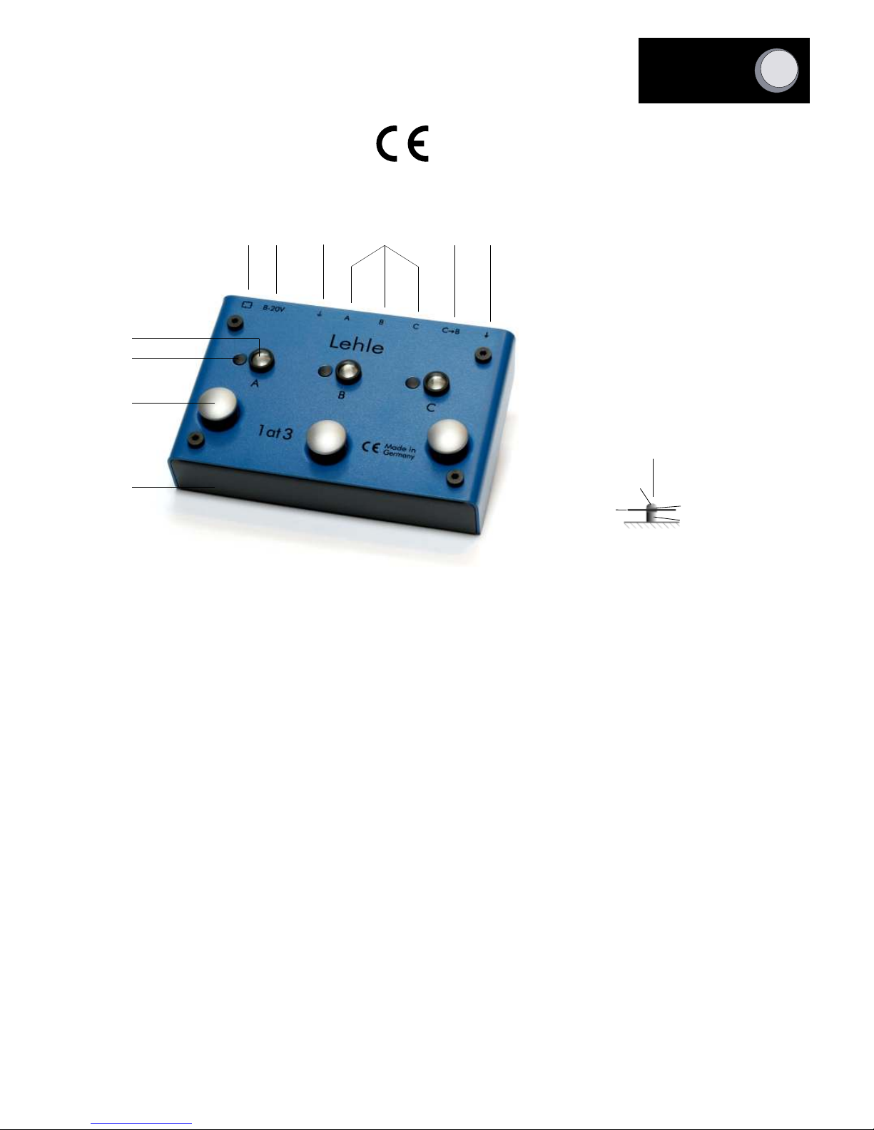
General Description
1 The input signal enters this socket. It is automatically routed to A if the Lehle 1@3 is
not active, and B and C are therefore muted.
2 If this socket is assigned and C is activated, the signal applied here is routed to B. In
this way, effect units can be serially routed into the amp, which is connected to B. Effects
which influence your sound even when not active can thus be bypassed by pressing the B
button. This means that they are in the signal path only when they are really needed.
3 The signal is routed with no semiconductors directly via gold-plated relays to Output A,
B or C. In case of a power unit failure the signal will be routed to A.
Lehle 1at3 SGoS
Lehle 1at3 SGoS
Lehle 1at3 SGoS
Lehle 1at3 SGoS
Lehle 1at3 SGoS
4 The grounds of Outputs A, B and C are connected to one another when this switch
is pressed. This is useful when you want to switch between channels of one amp.
Press this Ground switch if you want to route Outputs A, B and C to various amps
simultaneously; the outputs are then no longer electrically isolated, however, i.e., one
output (e.g. Output A) must be connected directly to the amp. For every other output
used for an amp, a transformer (e.g. the Lehle P-Split) should be interposed, in
order to avoid hum loops.
This Ground switch must remain pressed at all times in countries in which the amp
power supply is only two-core.
The Outputs A, B C are set to low impedance during switching when the Ground
switch is pressed, in order to suppress the natural switching noise of the gold-plated
relay contacts. This is accomplished under software control by means of the built-in
microcontroller. This circuit has absolutely no influence on the sound during normal
operation, i.e., when no switching is taking place, since it is not located in the signal
path.
5 The requires an 8 to 20V power supply . The supply voltage is
internally filtered and stabilized to guarantee trouble-free operation. A thermal cut-
out trips the unit automatically if a short-circuit occurs. The correct connector for the
power-supply socket of the is included in the pack. This can be
soldered on to the power adapter of your choice. It is advisable to use a separate
power adapter or an outlet on a multiple outlet power adapter with electrically
isolated outlets for the , but with no other loads connected to it, to
avoid interference noise during operation or when switching.
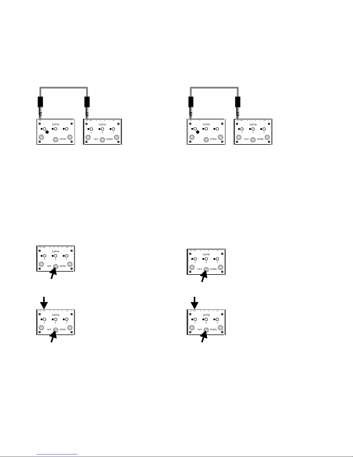
6 This jack socket is required for networking of the with other
Lehle SGoS Switchers and to transmit or receive MIDI program-change
commands. See the "MIDI capabilities of the " section for more
details.
7 The high-intensity LEDs under the lenses clearly indicate Switching State A, B or C,
even under stage lighting.
8 These programming buttons are used in Mode 2 and 3 (programmable modes) to
assign the switching states to the particular foot-switch. If a MIDI program-change
command has previously been received, the programming buttons can be used to
store switching states corresponding to the particular program-change command
(e.g. Amp A for Program-change Command No. 10 and Amp B for No. 11).
Irrespective of this, Outputs A, B and C can be switched on and off by pressing the
relevant programming buttons.
Storing programs is extremely simple:
If Output A, B or C is OFF in Mode 2 or 3 or after reception of a MIDI program-
change command, and should be ON, press the programming button and keep it
pressed until the LED flashes and then stays on automatically. If the particular output
should be OFF and it is in fact ON in Mode 3 or after receiving a program-change
command, press the programming button and keep it pressed until the LED flashes
and then remains OFF automatically. These assignments are stored in the built-in
Eeprom and are not lost even after the unit is switch off and on again.
9 The foot-switches with their virtually indestructible mechanisms actuate momentary
switches inside the switcher which trip Outputs A, B or C, depending on the mode
selected.
Mode selection
All three foot-switches must be pressed simultaneously to change the mode. When
the buttons are kept pressed, the LEDs will start to flash in sequence. After around 3
sec., one LED will remain on longer. A Lehle Dual SGoS in Mode 1 will be in Mode
2 after this mode-changing operation. From there, it can be switched to Mode 3,
from Mode 3 back to Mode 1.
The currently selected mode is backed-up in an Eeprom even after the Lehle Dual
SGoS has been switched off.
Mode 1: Green LED (left) on continuously
Mode 2: Yellow LED (center) on continuously
Mode 3: Red LED (right) on continuously
-2-
Technische Daten
Gewicht: 735 g
Länge: 10,3 cm
Breite: 15,6 cm
Höhe über alles: 4,7 cm
Spannungsbereich: 8-20 V DC
Max. Stromaufnahme: 97 mA
Allgemeine Beschreibung
1 In diese Buchse kommt das Eingangssignal. Ist der Lehle 1at3 SGoS ohne
Stromversorgung, liegt das Signal automatisch auf A an. B und C sind stummgeschaltet.
2 Ist diese Buchse belegt und C eingeschaltet, wird das hier angelegte Signal auf B geroutet.
Hiermit lassen sich Effektgeräte seriell auf den Amp einschleifen, der an B angeschlossen ist.
Effektgeräte, die selbst im ausgeschalteten Zustand den Sound beeinflussen, lassen sich
durch Betätigen des B-Tasters somit umgehen. D.h., sie befinden sich nur dann im Signalweg,
wenn man sie wirklich braucht.
3 Ohne Halbleiter geht das Signal direkt über goldkontaktierte Relais auf den Ausgang A, B
oder C. Für den Fall, dass das Netzgerät seinen Dienst versagt, ist A immer an.
4
Lehle 1at3 SGoS
Lehle 1at3
SGoS
Lehle 1at3 SGoS
Lehle 1at3 SGoS
Lehle 1at3 SGoS
Dieser Schalter verbindet im gedrückten Zustand die Massen der Ausgänge A ,B und
C. Das ist sinnvoll wenn man zwischen Kanälen eines Amps schaltet. Diesen Schalter
sollte man drücken, wenn die Ausgänge A, B und C gleichzeitig an verschiedenen
Verstärkern betrieben werden. Da die Ausgänge nun nicht mehr galvanisch getrennt
sind, muß ein Ausgang (z.B. A) direkt an den Verstärker angeschlossen werden. Bei
jedem weiteren Ausgang, der für einen Verstärker benutzt wird, sollte ein Übertrager
dazwischen geschaltet werden (wie z.B. Lehle P-Split), um Brummschleifen zu
vermeiden.
Um das natürliche Umschaltgeräusch der goldkontaktierten Relais zu dämpfen, werden
während des Umschaltens bei gedrücktem Masseschalter die Ausgänge A, B und C
niederohmig gemacht. Dies geschieht softwaregesteuert mit Hilfe des eingebauten
Micro-Controllers. Während des normalen Betriebs, in der umschaltfreien Zeit,
beeinflusst diese Schaltung den Sound in keinster Weise, da sie nicht im Signalweg liegt.
5 Der benötigt eine Stromversorgung zwischen 8-20V . Um einen
einwandfreien Betrieb zu garantieren, wird die Versorgungsspannung intern gefiltert und
stabilisiert. Ein Überhitzungsschutz schaltet im Falle eines Kurzschlusses das Gerät
automatisch ab. Ein passender Stecker für die Stromversorgungsbuchse des
liegt bei. Bei Bedarf kann dieser an das Netzteil der Wahl angelötet werden. Um
Störgeräusche beim Schalten oder im Betrieb zu vermeiden, ist es sinnvoll, ein eigenes
Netzteil oder einen Ausgang eines Mehrfachnetzteiles mit galvanisch getrennten
Ausgängen für den zu benutzen, ohne dass damit noch andere
Geräte mit angeschlossen sind.
6 Diese Klinkenbuchse wird benötigt um den mit anderen Lehle
SGoS Switchern zu vernetzen oder MIDI-Programchange Befehle zu empfangen bzw.
zu senden. Mehr dazu im Kapitel: „Die MIDI Eigenschaften des “
7 Die leuchtstarken Leuchtdioden unter den Lichtleitern lassen selbst bei Scheinwerferlicht
den Schaltzustand A, B oder C erkennen.
8 Diese Programmtaster dienen dazu im Betriebsmodus 2 und 3 (den programmierbaren
Modi) die Schaltzustände dem jeweiligen Fußtaster zuzuordnen. Wenn vorher ein MIDI-
Programchange Befehl empfangen wurde, kann man mit den Programmtastern
Schaltzustände passend zu dem jeweiligen Programchange Befehl abspeichern (z.B. Amp
A für Programchange Nr. 10 und und Amp B für Programchange Nr. 11). Unabhängig
davon kann man über die Programmtaster die Ausgänge A, B und C durch Drücken der
jeweiligen Taster an- bzw. ausschalten.
Das Abspeichern ist sehr einfach:
Wenn der Ausgang A, B oder C im Betriebsmodus 2 bzw. 3 oder nach empfangenem
MIDI-Programchange Befehl aus ist und an sein soll, drückt man den Programmtaster
und hält ihn solange gedrückt, bis die LED blinkt und dann durchgehend leuchtet. Soll
der jeweilige Ausgang aus sein, und dieser Ausgang ist im Modus 2 bzw. 3 oder nach
empfangenem Programchange an, drückt man den Programmtaster und hält ihn
solange gedrückt, bis die LED blinkt und dann von selbst aus bleibt. Diese Zuordnungen
werden in dem eingebauten Eeprom gespeichert und bleiben nach aus- und anschalten
des Gerätes erhalten.
9 Die Fußtaster mit ihrer nahezu unzerstörbaren Schaltmechanik betätigen im Inneren
des Switchers Taster, die je nach Betriebsmodus die Ausgänge A, B oder C auslösen.
Umschalten des Betriebsmodus
Zum Umschalten der Betriebsmodi müssen alle drei Fußtaster gleichzeitig gedrückt
werden. Hält man die Knöpfe gedrückt, fangen die LEDs an nacheinander zu blinken.
Nach etwa 3 sec bleibt eine LED länger an. Befindet sich der Lehle 1at3 SGoS im
Betriebsmodus 1, ist er nach Umschalten des Modus in Betriebsart 2. Von da lässt er sich
umstellen auf Modus 3. Nach Betriebsart 3 kommt man wieder in den Modus 1.
Der Betriebsmodus bleibt auch nachdem der Lehle 1at3 SGoS nicht mehr in Betrieb ist,
in einem Eeprom gespeichert.
Betriebsmodus 1: grüne LED (links) bleibt an
Betriebsmodus 2: gelbeLED (mitte) bleibt an
Betriebsmodus 3: rote LED (rechts) bleibt an
+_+_