Leica Geosystems ROD-EYE Basic User manual

ROD-EYE Mini and Basic
User Manual
Version 1.1
English

2
Rod-Eye Mini and Basic-1.1.0en
This manual contains important Safety Directions as
well as instructions for setting up the product and
operating it. Read carefully through the User Manual
before you switch on the instrument.
Copyright Notice
Copyright 2003 by Leica Geosystems, Inc. All rights reserved.
Leica Geosystems Proprietary Information
The information/data contained herein is proprietary information of Leica
Geosystems, Inc. and is furnished for your controlled use, and shall not be
copied or otherwise reproduced, nor in any manner disclosed to any third party,
without Leica Geosystems, Inc.'s prior written consent.

3Rod-Eye Mini and Basic-1.1.0en
TABLE OF CONTENTS
INTRODUCTION ............................................................................................4
ROD-EYE Mini (GENERAL CONSTRUCTION)........................................5
Front View........................................................................................................5
Rear View ........................................................................................................5
ROD-EYE Mini Operation................................................................................6
LCD Grade Indication ......................................................................................6
ROD-EYE Basic (INTERIOR APPLICATIONS)........................................7
BASIC FRONT VIEW ......................................................................................7
ROD-EYE Basic Operation..............................................................................8
ROD-EYE Mini Brackets..................................................................................9
MAINTENANCE............................................................................................10
WARRANTY..................................................................................................11
SPECIFICATIONS........................................................................................12
SAFETY DIRECTIONS................................................................................13

4INTRODUCTION
Rod-Eye Mini and Basic-1.1.0en
INTRODUCTION
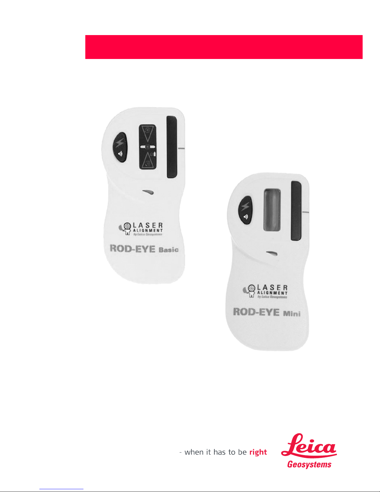
The ROD-EYE Mini and ROD-EYE
Basic sensors are designed to operate
with rotating lasers, to detect and
indicate the position of the plane of
laser light.
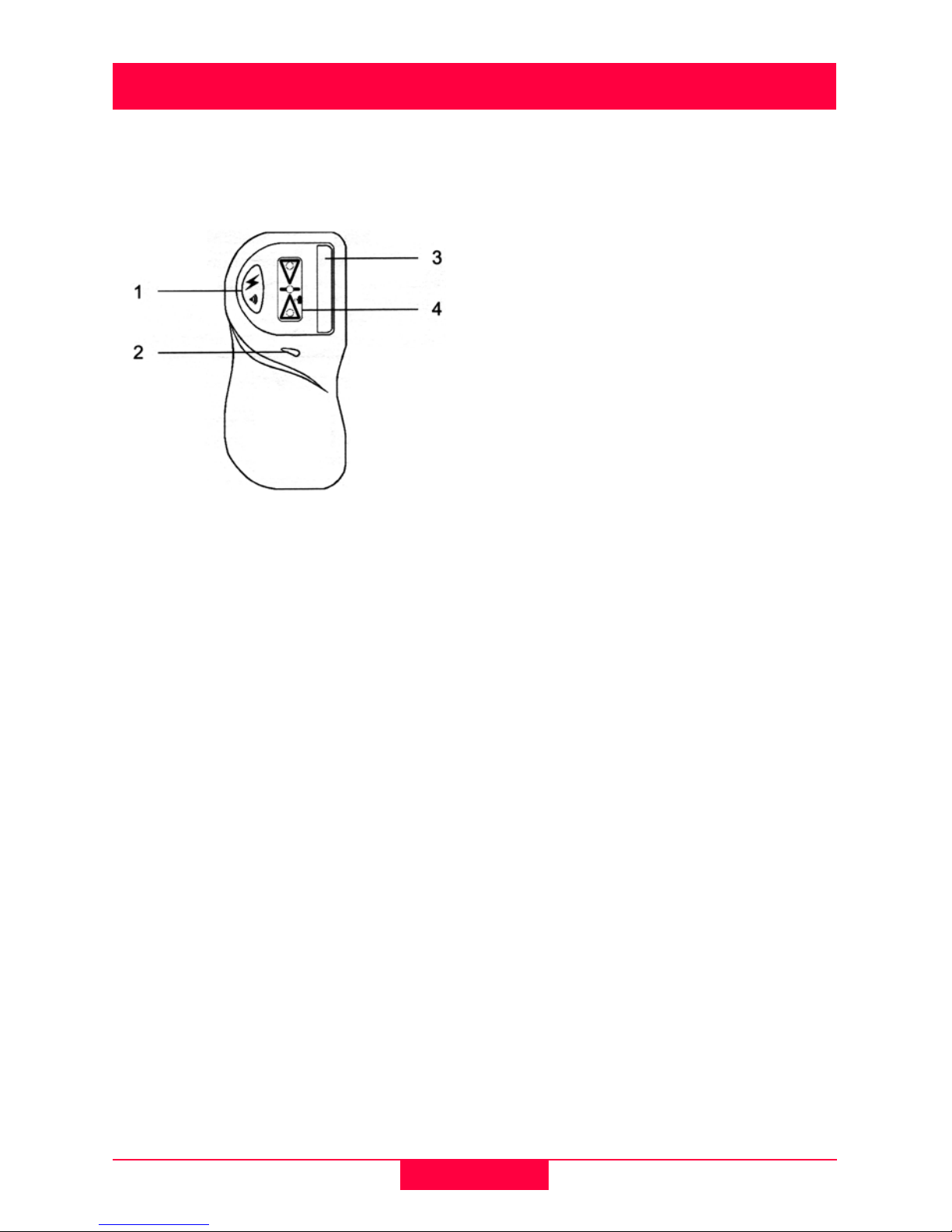
The ROD-EYE Mini is design for
general construction applications. The
Mini model has both an LCD indication
on the front panel that gives the
operator a visual indication, as well as
an audio indicator that emits three
distinct audio tones for high, low and
on-grade.
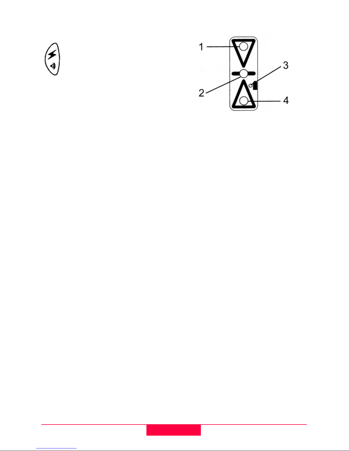
The ROD-EYE Basic for interior
applications is designed to work with
visible beam rotating lasers. The Basic
interior model has light emitting diodes
mounted in the display on the front
panel that gives the operator a bright
visual indication of the sensors
position. Like the Mini model, the Basic
model also has an audio indicator that
emits three distinct audio tones for
high, low and on-grade. This model
also has a magnet built into the top of
the housing to allow the sensor to be
easily attached to ceiling grid. A safety
strap is included with the sensor to
protect the sensor from falling.
All of Leica Geosystems's ROD-EYE
Sensors have been designed to be
used to typical construction
environments. They are built to be
rugged and withstand the abuse that
can occur in daily use, and at the same
time provide precise and repeatable
accuracy.

5Rod-Eye Mini and Basic-1.1.0en
ROD-EYE Mini (GENERAL CONSTRUCTION)
Front View
1Power Switch - Turns the detector
on and off and is used to select the
audio level. Press and hold the
switch for approximately two
seconds, and the sensor turns off.
2Audio Speaker - A fast beeping
signal indicates that the sensor is
too high. A solid tone indicates that
the sensor is on-grade. And, a slow
beeping signal indicates that the
sensor is too low.
3Laser Reception Window - The
set of photocells located behind this
window detect the laser beam. The
window (photocells) must be
directed towards the laser.
4Liquid Crystal Display (LCD) -
The LCD arrows indicate the
position of the sensor relative to the
laser beam.
Rear View
5Clamp Slots - Two dovetailed slots
for mounting the rod bracket.
6Tab Slot - Locks the rod clamp to
the sensor.
7Offset Notch - This notch is used
for transferring reference marks.
The notch is 1" (25 mm) below the
top of the sensor.
8Serial Number Label - Use as your
reference should you have any
questions regarding your sensor.
9Battery Compartment - The
compartment is watertight and
holds two "AA" alkaline batteries.
New batteries must be installed in
the positions noted on the diagram
found in the compartment. Use a
coin to open the battery door.

6ROD-EYE Mini (GENERAL CONSTRUCTION)
Rod-Eye Mini and Basic-1.1.0en
ROD-EYE Mini Operation
Press the Power Button
once to turn on the sensor.
The beeper will sound and
all the symbols on the LCD
will be displayed. The power
symbol will be displayed,
indicating that the sensor is
turned on.
Pressing the Power Button again will
toggle the sensor through the audio
volumes (High, low and off). Pressing
and holding the switch for
approximately two seconds will turn
the sensor off.
The sensor will automatically shut off
after 30 minutes on non-use.
Direct the front of the sensor towards
the laser beam to detect the rotating
laser. When the photocells are
activated by the laser, the LCD and
audio will immediately begin indicating
the position of the beam as it strikes
the sensor.
A low battery indicator will appear
when there is approximately one hour
of life left in the battery.
LCD Grade Indication
1PowerOn
2 Low Battery Indicator
3High
4 On-grade
5 Low

7Rod-Eye Mini and Basic-1.1.0en
ROD-EYE Basic (INTERIOR APPLICATIONS)
BASIC FRONT VIEW
1Power Switch - Turns the detector
on and off and is used to select the
audio level. Press and hold the
switch for approximately two
seconds, and the sensor turns off.
2Audio Speaker - A fast beeping
signal indicates that the sensor is
too high. A solid tone indicates that
the sensor is on-grade. And, a slow
beeping signal indicates that the
sensor is too low.
3Laser Reception Window - The
set of photocells located behind this
window detect the laser beam. The
window (photocells) must be
directed towards the laser.
4Light Emitting Diode (LED)
Display - The LED's indicate the
position of the sensor relative to the
laser beam. The center, green LED
will flash slowly to indicate that the
sensor is on. A smaller LED to the
side of the arrows will indicate
when the batteries are low.
5Magnetic Mount - A magnet built
into the top of the housing is used to
attach the sensor to ceiling grid.

8ROD-EYE Basic (INTERIOR APPLICATIONS)
Rod-Eye Mini and Basic-1.1.0en
ROD-EYE Basic Operation
Press the Power Button once
to turn on the sensor. The
beeper will sound and the
LED's will flash. The center
green LED will continue to
flash slowly, indicating that
the sensor is turned on.
Pressing the Power Button again will
toggle the sensor through the audio
volumes (High, low and off). Pressing
and holding the switch for
approximately two seconds will turn
the sensor off.
The sensor will automatically shut off
after 30 minutes on non-use.
Direct the front of the sensor towards
the laser beam to detect the rotating
laser. When the photocells are
activated by the laser, the LCD and
audio will immediately begin indicating
the position of the beam as it strikes
the sensor.
The amber low battery LED indicator
will appear when there is
approximately one hour of life left in
the battery.
A safety clip attaches to the back of the
sensor. Attach the sensor to the ceiling
grid with a string to protect it against
falling.
1 Red Light - High Indication
2 green Light - On-grade
3 Amber Light - Low Battery
Indication
4 Red Light - Low Indication

9Rod-Eye Mini and Basic-1.1.0en
ROD-EYE Basic (INTERIOR APPLICATIONS)
ROD-EYE Mini Brackets
A general purpose Grade Rod Bracket
comes with the ROD-EYE Mini Sensor
for mounting to grade rods. To secure
the bracket to the detector, slide the
dovetail on the bracket into the
grooves on the back of the detector. A
snapping action will ensure that the
bracket is securely attached.
To remove the bracket, depress the
thumb release tab and slide the
bracket upward.
1Bracket Locking and Release
Tab - for securing and releasing the
bracket from the sensor.
2Dovetail Slots - attached bracket
to the detector.
3Reference Indicators - aligned
with the on-grade mark of the
sensor.
4Clamping Screw - Tightens the
bracket to the grade rod.
A Safety Bracket and Strap (lanyard)
comes with the ROD-EYE Basic
Sensor for providing a safety
attachment when using the sensor's
magnetic mount attached to ceiling
grid.
1 Dovetail Slots
2 Thumb Release

10 MAINTENANCE
Rod-Eye Mini and Basic-1.1.0en
MAINTENANCE
Keep it Clean.
Clean the front of your ROD-EYE
Sensor with a mild detergent and a soft
cloth. Do not use your fingers or a dry
cloth to clean the window(s). Take care
not to scratch the glass on the laser
reception window.
The ROD-EYE Sensor contains
static sensitive components.
Do not attempt any internal repairs on
your unit. Opening the sensor will void
the warranty.
Take care of your batteries.
The ROD-EYE Sensor uses two "AA"
alkaline batteries. Remove the
batteries if the sensor is to be stored
for a period of time. Avoid extreme
temperatures that can cause battery
degradation and early failure of the
batteries.
Contact your dealer, Leica
Geosystems, or an Authorized Factory
Service Center if you have questions
regarding your ROD-EYE Mini or
ROD-EYE Basic Sensor.

11 Rod-Eye Mini and Basic-1.1.0en
WARRANTY
WARRANTY
Your ROD-EYE Sensor is guaranteed
against defects in materials and
workmanship under normal use and
service for a period of 12 months
provided that the ROD-EYE Sensor
has been properly used and cared for
as stated in the User Manual. Any
evidence of an attempt to repair the
ROD-EYE Sensor by other than
factory authorized personnel using
Leica Geosystems certified
replacement parts, will automatically
void the warranty.
Leica Geosystems's liability under this
warranty is limited to repairing or
replacing any product returned to a
factory authorized service center for
that purpose. The foregoing states the
entire liability of Leica Geosystems,
Inc. in connection with the ROD-EYE
Sensor, and they shall not be held
responsible for any consequential
damage of any kind. The foregoing is
in lieu of all other warranties expressed
or implied.

12 SPECIFICATIONS
Rod-Eye Mini and Basic-1.1.0en
SPECIFICATIONS
Specifications are subject to change without notice.
ROD-EYE Mini ROD-EYE Basic
Detection Accuracy
(Typical) ±0.080" (±2.0 mm) ±0.030" (±.75 mm)
Display LCD LED
Sealing Dustproof, Waterproof Dustproof, Waterproof
Detection Range (depen-
dent on laser) Up to 500' (150 m) Radius Up to 300' (90 m) Radius
Mounting Rod Bracket Magnetic Mount, Safety Clip
Audio Volumes High 100+ dBA
Low 65 dBA High 100+ dBA
Low 65 dBA
Display Channels Three Three
Window Capture Height 1.5" (38 mm) 1.5" (38 mm)
Reception Angle ±45 ±45
Offset Notch 1" (25 mm) 1" (25 mm)
Low Battery Indication Yes (LCD symbol) Yes (Amber LED)
Battery Life 200+ Hours 100+ Hours
Battery Size Two "AA" Two "AA"
Automatic Shut-off 30 Minutes 30 Minutes
Operating Temperature -4°F to +140°F
(-20°C to +60°C) -4°F to +140°F
(-20°C to +60°C)
Approximate Size 4.5 x 2.1 x 1.3"
(114 x 53 x 32 mm) 4.5 x 2.1 x 1.3"
(114 x 53 x 32 mm)

13 Rod-Eye Mini and Basic-1.1.0en
SAFETY DIRECTIONS
SAFETY DIRECTIONS
The symbols used in the User Manual
have the following meaning:
DANGER:
Indicates an imminently
hazardous situation which, if not
avoided, will result in death or serious
injury.
WARNING:
Indicates a potentially
hazardous situation or an unintended
use which, if not avoided, could result
in death or serious injury.
CAUTION:
Indicates a potentially
hazardous situation or an unintended
use which, if not avoided, may result in
minor or moderate injury and/or
appreciable material, financial and
environmental damage.
)Important paragraphs which
must be adhered to in practice as they
enable the product to be used in a
technically correct and efficient
manner.
The following directions should enable
the person responsible for the product,
and the person who actually uses the
product, to anticipate and avoid
operational hazards. The person
responsible for the product must
ensure that all users understand these
directions and adhere to them.
Intended Use of Instruments
Permitted uses
The ROD-EYE Mini and Basic are
intended for the following applications:
• Detecting a rotating laser beam.
Prohibited uses
• Use of the product without
instruction.
• Use outside of the intended limits.
• Disabling safety systems.
• Removal of hazard notices.
• Opening the product using tools
(i.e. screwdriver) unless this is
specifically permitted for certain
functions.
• Modification or conversion of the
instrument.
• Use after misappropriation.
• Use with accessories from other
manufacturers without the prior
express approval of Leica
Geosystems.
WARNING:
Adverse use can lead to injury,
malfunction, and material damage. It is
the task of the person responsible for
the instrument to inform the user about
hazards and how to counteract them.
The laser unit is not to be used until the
user has been instructed how to work
with it.

14 SAFETY DIRECTIONS
Rod-Eye Mini and Basic-1.1.0en
Limits of Use
See section "Specifications."
Environment:
Suitable for use in an atmosphere
appropriate for permanent human
habitation: not suitable for use in
aggressive or explosive environment.
Responsibilities
Area of responsibility of the manu-
facturer of the original equipment
Leica Geosystems AG, Heerbrugg
(hereinafter referred to as Leica
Geosystems):
Leica Geosystems is responsible for
supplying the product, including the
user manual and original accessories,
in a completely-safe condition.
Responsibilities of the manufac-
turers of non-Leica Geosystems
accessories:
The manufacturers of non-Leica
Geosystems accessories for the
product are responsible for
developing, implementing and
communicating safety concepts for
their products, and are also
responsible for the effectiveness of
those safety concepts in combination
with the Leica Geosystems product.
Responsibilities of the person in
charge of the product:
WARNING:
The person responsible for the
product must ensure that it is used in
accordance with the instructions. This
person is also accountable for the
training and the deployment of
personnel who use the instrument and
for the safety of the equipment in use.
The person in charge of the instrument
has the following duties:
• To understand the safety
instructions on the product and the
instructions in the user manual;
• To be familiar with local regulations
relating to accident prevention;
• To inform Leica Geosystems
immediately if the equipment
becomes unsafe.

15 Rod-Eye Mini and Basic-1.1.0en
SAFETY DIRECTIONS
Hazards of Use
Main hazards of use
WARNING:
The absence of instruction, or
the inadequate imparting of
instruction, can lead to incorrect or
adverse use, and can give rise to
accidents with far-reaching human,
material, financial, and environmental
consequences.
Precautions: All users must follow the
safety directions given by the
manufacturer and the directions of the
person responsible for the product.
CAUTION:
Watch out for erroneous
measurements if the product is
defective or if it has been dropped or
has been misused or modified.
Precautions: Periodically carry out
test measurements and perform the
field adjustments indicated in the user
manual, particularly after the product
has been subjected to abnormal use
and after important measurements.
CAUTION:
If the accessories used with the
equipment are not properly secured
and the equipment is subjected to
mechanical shock (i.e. blows, falling),
the equipment may be damaged or
people may sustain injury.
Precautions: When setting-up the
product, make sure that the
accessories (i.e. tripod, tribrach,
connecting cables) are correctly
adapted, fitted, secured, and locked in
position. Avoid subjecting the
equipment to mechanical shock.
WARNING:
If the product is improperly
disposed of, the following can happen:
• If polymer parts are burnt,
poisonous gases are produced
which may impair health.
• If batteries are damaged or are
heated strongly, they can explode
and cause poisoning, burning,
corrosion or environmental
contamination.
• By disposing of the product
irresponsibly you may enable
unauthorized persons to use it in
contravention of the regulations,
exposing them-selves and third
parties to the risk of severe injury
and rendering the en-vironment
liable to contamination.
• Improper disposal of silicone oil
may cause environmental
contamination.
Precautions:
The product must not be
disposed with household
waste.
Dispose of the product appropriately in
accordance with the national regula-
tions in force in your country.
Always prevent access to the product
by unauthorized personnel.

16 SAFETY DIRECTIONS
Rod-Eye Mini and Basic-1.1.0en
Product specific treatment and waste
management information can be
downloaded from the Leica
Geosystems home page at http://
www.leica-geosystems.com/treatment
or received from your Leica
Geosystems dealer.
Electromagnetic Compatibility
(EMC)
The term "electromagnetic
compatibility" is taken to mean the
capability of the product to function
smoothly in an environment where
electromagnetic radiation and
electrostatic discharges are present,
and without causing electromagnetic
disturbances to other equipment.
WARNING:
Electromagnetic radiation can
cause disturbances in other
equipment.
Precautions: Although the product
meets the strict regulations and
standards which are in force in this
respect, Leica Geosystems cannot
completely exclude the possibility that
other equipment may be disturbed.
CAUTION:
There is a risk that disturbances
may be caused in other equipment if
the product is used in conjunction with
accessories from other manufacturers,
i.e. walkie-talkies, non-standard
cables, external batteries.
Precautions: Use only the equipment
and accessories recommended by
Leica Geosystems. When combined
with the product, they meet the strict
requirements stipulated by the
guidelines and standards.
CAUTION:
Disturbances caused by
electromagnetic radiation can result in
the tolerance limits for measurements
being exceeded.
Precautions: Although the product
meets the strict regulations and
standards which are in force in this
connection, Leica Geosystems cannot
completely exclude the possibility that
the product may be disturbed by very
intense electromagnetic radiation, i.e.
near radio transmitters, walkie-talkies,
diesel generators. Check the
plausibility of results obtained under
these conditions.
FCC Statement
(applicable in the U.S.)
WARNING:
This equipment has been tested
and found to comply with the limits for
a Class B digital device, pursuant to
part 15 of the FCC rules.

17 Rod-Eye Mini and Basic-1.1.0en
SAFETY DIRECTIONS
These limits are designed to provide
reasonable protection against harmful
interference in a residential
installation. This equipment generates,
uses and can radiate frequency energy
and, if not installed and used in
accordance with the instructions, may
cause harmful interference to radio
communications.
However, there is no guarantee that
interference will not occur in a
particular installation.
If this equipment does cause harmful
interference to radio or television
reception, which can be determined by
turning the equipment off and on, the
user is encouraged to try to correct the
interference by one or more of the
following measures:
• Increase the separation between
the equipment and the receiver.
• Consult the dealer or an
experienced radio/TV technician for
help.
• Reorient or relocate the receiving
antenna.
• Connect the equipment into an
outlet on a circuit different from that
to which the receiver is connected.
WARNING:
Changes or modifications not
expressly approved by Leica
Geosystems could void the user's
authority to operate the equipment.
Product Labeling:
ROD-EYE Mini - Rear View
ROD-EYE Basic - Rear View

18 SAFETY DIRECTIONS
Rod-Eye Mini and Basic-1.1.0en

19 Rod-Eye Mini and Basic-1.1.0en
SAFETY DIRECTIONS

Leica Geosystems AG
CH-9435 Heerbrugg
(Switzerland)
Phone +41 71 727 31 31
Fax +41 71 727 46 73
www.leica-geosystems.com
Leica Geosystems AG,
Heerbrugg, Switzerland,
has been certified as being
equipped with a quality
system which meets the
International Standards of
Quality Management and
Quality Systems (ISO
standard 9001) and
Environmental
Management Systems
(ISO standard 14001).
730739-1.1.0en
Printed in Switzerland.
Copyright Leica Geosystems AG, Heerbrugg,
Switzerland, 2006
(Original text)
Total Quality Management -
Our commitment to total
customer satisfaction.
Ask your local Leica
Geosystems agent for more
information about our TQM
program.
This manual suits for next models
1
Table of contents
Other Leica Geosystems Accessories manuals