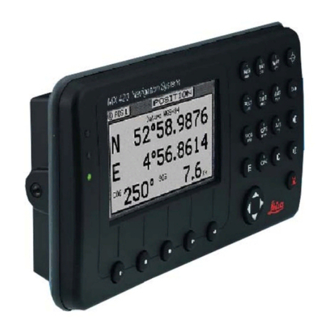
Leica MX420 User manual


Table
of
Contents Table ofContents
Operator's
Manual
About
GPSNavigation ,1
Special Notes ,.." .., , ,
",
..
",
,.,..
,."",.2
GPS
,2
OGPS
" , 2
Charts
and
Navigati0n.al
Aids
2
Functional Description , , , 3
MX420 Configurations .'
',
, , , ,', ,', , 3
MX42012
GPS 3
MX42012
OGPS
3
MX420lSGPS 3
MX420lS
OGPS
3
MX420IBR 4
MX420lBRIM
(Dual
Control
Integrity
Monitor)
4
.....
MX420lAIS
Basic
(Automatic
Identification
System-Basic) 5
MX420lAIS (AIS &Navigation System) 5
OGPS
Beacon System 6
Keypad &Display Description 7
Differential
GPS
Traffic
Light
Operation: 8
Red Flashing S
Red/Yellow
Solid
8
Red
Solid
S
Yellow/Green
Solid
8
Yellow Solid 9
Green Solid . . 9
GPSTraffic Light Operation: 9
Red Flashing .9
~&~~w~~....................................................
9
RedSolid .9
Yellow Solid .. .
70
Green Solid ..
".
...
70
The Display:
70
Version
7.5

Operator's Manual
Table
of
Contents
o
The
Softkeys:
77
The
Function
Keys:
77
@Mark Position
17
@
GOTO.....................................
72
@
LIGHT
72
®
POWER
ON/OFF
72
@MAN
OVER
BOARD
(MOB)
73
oE
(EDIT)
74
8C
(CLEAR)
74
o
CURSOR...............................................................
74
~
FUNCTION
74
/'-9-'
:
A1S)
Automatic Identification System (AIS) .
76
,
-f!./
Navigate
77
Dead Reckoning
78
(It
A.
VI -
The
Pnnnrama
Screen.................
. ..
78
NAV2 -Basic Steering Information.. 21
NAV 3 - Expancfcd Navigation
Information....
22
NAV4
-Sensor Input Navigation.................
..
23
ROLJte
27
(rmting
iI
Route Usinq the (;' no
Key
rnE7
-
The
Acl/l/c;
Route
...................................... 28
.
....
29
??
,;
.::

Table
of
Contents Operator's
Manual
Creating
aMulti-WaypointActive
Route
33
InsertBy
Number
34
Choose
in
Bank
34
InsertNew
Waypoint
36
Insert
Route
37
Maneuvering
Within
the
Route
::
38
. . .-
Scrolling : : : 38
Skipping
andUnpassing
Waypoints ..: : 38
Inserting Waypoints
or
Routes
into
an ExistingRoute 39
Reversing the
Active
Route :;..: ,
41
ETA
Setup
~
:·
43
SOGBased on
Arrival
Date &Time:
44
ETA Basedon Speed: :
44
RTE2
-
The
Route
Bank
44
Waypoint
47
CreatingandEditing Waypoints
48
Waypoint Lock/Unlock
53
Removing Waypoints :55
Moving waypoints 57
Downloading Waypoints &
Routes
to OtherDevices
58
Rnn -Routes: 59
RTE-Active Route:
59
WPL -Waypoint Location -NMEA 0183Standard: 60
WPL -Waypoint
with
Symbols &Description -NMEA 0183
Expanded: 61
Downloading Waypoints toa PersonalComputer
67
Uploading Waypoints
from
OtherDevices 63
Uploading Waypoints
from
a PersonalComputer
64
Version
1.5
11/

@Mark or
Event
66
'.;
Operator'sManual
Table
of
Contents
S
GOTO
67
Plot
70
PLOT
1- Relative to Boat
72
ModifyingtheActive
Route
Using
thePlotScreen
72
Customizing
theDisplay
74
PLOT
2 - Relative to Marker
77
PLOT3
77
Plot Screen Use
Examples
78
Station
Keeping
78
GridSearch
79
@Man
Over
Board
80
Remote MOB
81
Tide
82
TlOE1
-Current
Tide
Display
82
TlOE2
-
Tide
Table
Port
List 83
Adding aPort
85
Auxiliary
87
AUX1
-Alarm
Log
:
87
AUX2
-
Speed
Graph
88
AUX3
-Not
Used
88
AUX4
-
Sun
Almanac
88
AUX5
-Moon
Phases
89
AUX6
-Batteries 89
AUXI -Unitinformation
90
IV
Version
1.5

Table
of
Contents Operator's
Manual
Position "
97
POSl -Position Display
(Large)
91
Loran-C
92
UTM
92
POS2
-Position, Altitude, Magnetic Variation, &
Time
93
POS3
-Position &Log 93
GPS
., ,
95
GPSl -
GPS
StatusScreen
95
GPS6
-
DGPS
STA
TUS
96
GPS7
-
DGPS
Messages
98
Configuration ,99
AIS Static
99
AIS
Voyage
99
""'
e- Alarms , ,99
•
Anchor -Anchor
Watch
Alarm
100
COG
SOG-
Course
&SpeedFilterSettings &Setup
100
Compass
-External
Compass
Input&Magnetic Variation
Table
101
Datum
-CurrentPosition Calculation
102
Depth
-
NMEA
InputControl
103
DGPS
-
DGPS
Configuration
104
DR
-DeadReckoning
106
Dual
Contr.
-DualStation Control
106
GPS
-Elevation Mask Control
107
Init
Pos
-Initial Position Entry
107
Language
-
Language
Configuration
108
Version 75 v

Operator's Manual
Table
of
Contents.
Lighting -Display/Keyboard Light &Contrast
Control
109
Log
-Speed
Log
Input
(Pulse
or
NMEA
0183)
109
Log
Pulses -
GPS
SOG
Log
Pulse
Output
111
MX480
-
MX480
PC
Chart
Interface Control
711
Navigation -
Neviqetion
Method &Waypoint
Pass
Criterion
Control
712
NMEA
Out 1
through
n* -
NMEA
0183
Output
Data
Control
115
Other
Special
Cases
Affecting
NMEA
0183
Records:
720
Operation
-
General
Setup
and ControlSettings
721
Organizer
-Automated Message Reminders
722
Position
-Positioning
Reference,
Mode, &AlarmControl.
723
Printout 2 - Printer
Output
Control
725
ROT
(Rate
of
Turn)
728
Security
728
Serial
110
729
Time
-Mode and
Format
Control
729
Wind
730
Wpt &Rte Input-
Uploading
Waypoints into
the
Receiver.
731
Appendix A -Automatic Identification System
(AIS)
733
Introduction
733
AIS System
Setup
742
Configuring
the
AISStaticSetup
742
Configuring
the
AIS
Voyage
747
AIS Function
Key
750
AIS
7-
OWN
SHIP
DATA
750
AIS
2 -
Remote
Ship
List
752
AIS
3 -
RECEIVED
(RX)
SAFETY
MESSAGES
754
AIS
4 -
TRANSMIT
(TX)
SAFETY
MESSAGE
755
/',/55 -
T:-.'
Safety
List........................................... .
757
VI Vers:
~
.')
7.
5

Table
of
Contents Operator's Manual
AIS 6 -
REGIONAL
AREAS
758
AIS
7-
LONG
RANGE
(LR)
DISPLAY
~
767
AIS8
-AIS
DATA
LINK
STATUS
763
AIS 9 - AIS
STATUS
764
AIS
70
-AISPassword
765
PLOT
3- AISPlotScreen
167
AppendixB-
Datum
List
168
Appendix,C -BeaconList..
169
Appendix D- Engineering Mode
183
AUX7
-UnitInformation &Self
Test
783
CDU
ColdStart-Clearing Memoryto Factory Default
785
GPS
-
GPS
CDU
Troubleshooting
786
GPS3
-
Visible
Satellite Information
786
"
GPS4
-
GPS
Position Uncertainty
787
GPS5
-
GPS
Debug
Screen
787
MX427
Reset
790
"
Appendix E-DualControl
Head
Mode
191
AppendixF-Demonstration Mode
195
Glossary
197
Version
7.5
VII

Scope OfThis Manual
This manual reflects
the
software capabilities in version 1.5 software.
We have attempted to take care and develop manuals which provide
in-depth information. Where possible, we have attempted not only to
describe what you
see
on
the
screen, but how to understand and use
it as well. Obviously,
we
can't
teach you how to navigate, but we can
help make your work,more thorough and enjoyable. Throughout the
manual, you will find helpful hints about the interaction
of
various
functions. In a piece
of
equipment that has the many capabilities
of
this receiver, importantdetails can sometimes become obscured in one
Or
two lines
of
text.
In
our
effortto ensure you get the most out
ofthis
documentation, and to protectagainstimportantdetails becoming lost,
don't
be surprised
if
you
see the sameor similarinformation more than
once.
This manual is organized by describing first the various MX420 mod-
els covered in this book. Then:the special front panel features includ-
ing the traffic light indicator. The sections that follow detail each pri-
mary functionasitis presentedon the front panel(i.e. NAV, RTE, WPT,
PLOT, ...CFG).The appedixes describe important details about special
functions.
Appendix-A is a special section describing the AlS displays and set-
ups
of
the MX420/AIS model.
We hope you find the manual enjoyable and informative reading. As
always, we welcome your comments on improving our products or
manuals. We wouldn't mind
if
you wrote to tell us that we did the
job
right the first time either. You can find a Reader Comment Card at the
back
of
the manual.
Related Documents
MX 420 Installation&Service Manual (PIN 3508 10270060)
MX 420 QuickReference Guide (PIN 3508
102
70050)
MX420lAIS Reference Card (PIN 725626) (for AlS models only)

How
To
Contact
Us
For Installation, Service
and
Technical Support:
Contact your local
Leica
(MX-Marine) dealer
ForSales
of
Accessories:
Contact your local
Leica
(MX-Marine) dealer
For Hardware and
Software
Upgrades:
Contact your local
Leica
(MX-Marine) dealer
Unlike many other
consumer
electronics industries that
only
sell con-
sumer electronic devices, your marine dealer is often
your
best advi-
sorfor installationand service
of
yournewGPS receiver. Leicastrongly
encourages you to
utilize
the
knowledge andexperience
of
yoursales
and service dealer.
Should you need to
contact
us directly, we
can
be
reached
at the fol-
lowing for new sales,
upgrades,
repair service,
or
technical support:
International:
Leica Geosysterr.s,
Inc.
MX-Marine
23868 Hawthome BIvd., Suite 200
Torrance,California 90505
USA
+01-310-791-8213 Telephone (International)
+01-310-791-6108 Fax
,.,.""
....
Y.r.1X
-marme.
corn
In Europe:
Leica Geosystems
A/S
MX-Marine
Hok<erl2A
DK-2730 Herlev
Denmark
+45-44-54-03-00Telephone
+45-44-54-03-30 Sales Fax

MX420 Navigation System
MX42012GPS
MX42012
DGPS
MX42018
GPS
MX42018
DGPS
MX420lBR
MX420lBRIM
MX420lAIS Basic
(MKD)
MX420lAIS
DGPS
Product Information
The model and serial number
of
your instrument are given on
the instrument.
Enter
the model and serial number in the
spaces provided below. Always refer to this information when
you contact your dealer.
MX420 CDU Serial No.: _
MX421 GPS
Antenna
SIN: _
i!
CopyrightOctober, 2002
Doe.
PIN3508
102
70040

Symbols
UsedIn
This
Manual
.Danger
Indicates an imminently hazardous situation which,
ifnot
avoided,
will result indeath
or
serious injury.
Warning
Indicates apotentially hazardous situation which,
if
not avoided,
could result indeath or serious injury.
Caution
Indicates apotentiallyhazardous situation which,
if
not avoided, may
result in minor or moderate injury and/or appreciable material, finan-
cial andenvironmentaldamage.This symbol isalsoused to alertagainst
unsafe practices.
Important paragraphs which must be adhered to in practice, as they
•
enable the product to be used in a technically correct and efficient
manner,
This manual contains important safety directions as well as instruc-
tions for setting up the instrument and operating it. Read carefully
through the Operator's Manual, Options Manual, and Installation
&Service Manual before you switch on the instrument.

About
GPSNavigation
About
GPSNavigation
Operator's Manual
Version
7.5
This GPS receiver is a precision navigation instrument utilizing the
latest technology available today to provide optimum performance
. from the GPS satellite and Beacon land signals received. As with all
other forms
of
radio signals, the ultimate navigation result is depen-
dent upon the quality
of
these signals. Radio signals may, on occa-
sion;be distorted, jammed,
or
otherwise incorrect. As a result, your
positionaccuracy may occasionally be less than that which can nor-
mally be expected. -
The NavstarGlobal Positioning System, commonly referred to as GPS,
is a satellite navigation system developed by the V.S. Department
of
Defense to provide both military and civilian users with highly accu-
rate, worldwide, three dimensional navigation and time. By receiving
signals from orbiting GPS satellites, authorized users are able to con-
tinuously navigate with an accuracy on the order
of
16meters or bet-
ter, while civilian users are limited to accuracy's
of
approximately 30
meters 2D RMS.
A technique referred to as Differential GPS (DGPS), allows users to
obtain maximumaccuracy from the GPS system. DGPS requires the use
of
two GPSreceivers. Onereceiver, known as theRe/erenceStation,is
placed at a surveyed location, the coordinates
of
which are precisely
known. The purpose
ofthe
differential GPS system is to use the refer-
ence station to measure the errors in the GPS signals and to compute
corrections to remove the errors. The corrections are then communi-
cated in real-time to the navigators, where they are combined with the
satellite signals received by the navigators, thereby improving their
navigation or positioning. The geographic validity
of
these correc-
tions decreases with distance from the reference station, but the cor-
rections are valid for navigators hundreds
of
kilometers fromthe refer-
ence station.
Marine radio beacons operating in the 283.5 to 325.0 KHz frequency
range are in widespread use for direction finding in coastal navigation.
Because the beacon system has been in place and widely used for
many years, it provides an effective means for the transmission
of
DGPS signals. Depending on their local environment and power out-
put, their signals may be usable to several hundred miles. Marine bea-
cons provide an economical means
of
obtaining DGPS accuracy for
coastal navigators. GPS receivers with built-in beacon receivers are
designed to provide low cost reception
of
DGPS corrections broad-
cast (normally free
of
charge) by coastal authorities.
7

operator's
Manual
Special Notes
GPS
About
GPS
Navigation
Neverrely solely
on
anysingle navigational aid. Alwaysuse whatever
information is available, and cross-check information when possible.
GPS expected position accuracy is better than
30
meters (95%
of
the
time) but maybe
up
to 100meters occasionally.
The
derived speedand
course readings
may
be hampered accordingly.
The
GPS system was
declared operational in 1994; however, the
system's
availability and
accuracy are subjectto change atthe discretion
of
the USDepartment
of
Defense.
OGPS
This GPSreceiver'spositionaccuracy is improved to 5metersorbetter
for 95%
of
the time, subjectto theavailability, accuracy,andcontrolOf
the DGPS correction transmission from the
Beacon
Station, or other
reference station connected at the time
of
usage.
The differential
GPS
positionisthat
ofthe
navigatorGPS antenna, and
not that
of
the
beacon
antenna,
if
aseparate
beacon
antenna is in use.
In addition, the
beacon
radio signal which carries the DGPS correc-
tions may be
hampered
by weather conditions such as heavy rain,
snow, and thunder storms. The beacon radio signal may also be inter-
rupted by powerful radio transmitters operating in long wavelength
bands.
Charts
and
Navigational Aids
Positions obtained from charts are not always as accurate as your
navigator (due to environmental changes, the
dates
of
charts, and
datum offsets
if
the
datum differs from the one in use by the naviga-
tor). The position
of
a floating aid can differ due to tide. set and drift.
zVersion
7.5

.
-.
About GPSNavigation
..'
Functional Description
MX420
Configurations
Operator's Manual
The MX420 Navigation System is available in several configurations.
Pleasereferto the Auxiliary Unit Information section
of
the manual to
view
sample screens to identify your particular model. Described be-
low
are the various MX420 configurations and their differences.
MX42012GPS
This isabasic MX420Control and DisplayUnit(CDU) model with two
(2) bidirectional user1\'MEAports. This mode! is supplied with aMX42 I
GPS only smart antenna. The MX421antenna
can
achieve autono-
mous
GPS accuracy better than 3meters.
MX421
Smart
GPs.~~~~
Antenna -
MX420CDU
~
.
,
"',
.
..
:'
::~-'
.
•••
•
.:
•••
"'."
!I.
Basic MX420/2
and
MX420/B GPS &DGPS Configuration
MX42012
DGPS
This is a basic
MX420/2
CDU supplied with acombined GPS and
Beaconsmartantenna (MX421B). The MX421B DGPS unitcan achieve
sub-meter accuracy in areas with good beacon differential coverage.
MX420lBGPS
This isan enhanced MX420 CDUequipped witheight(8) bidirectional
user
NMEA ports. This model can be configured to outputan optional
1Pulse Per Second (PPS) timing output.
It
is suppliedwith a GPS only
smart antenna model MX421.
MX420lB
DGPS
This is a basic
MX420/8
CDU supplied with asmart DGPS antenna
model
MX421
B.
Version
7.5
3

Operator's Manual Functional Description
MX420lBR
This is a dual-head CDU system where a MX420/8 (operating as a
master) and a MX42012 (operating as a slave) aresupplied, A smart
DGPS antenna
(MX42IB)
is supplied as a standard equipment. The
antenna unit is connected only to the MX420/8 masterunit.
2.::"~
MX420
CXIU
-j
MX420
axJ
~
i.::
:1
~
..
fEtl
-.;~'~·f
'.
~
.~
~.
~!'?
.........
~
.'
...•...
.
..
MX420 BR
Beacon
and
Remote Configuration
MX420lBRIM
(Dua/
Contro/lntegrity
Monitor)
This is an enhanced Dual-Control configuration whereintwo MX420/
8 CDUs and two MX421B smart DGPSantennas are supplied. These
two MX420/8 units are connected in dual-control configuration but
they operate as independentnavigator units with dedicatedMX42lB
antennas. TheIntegrity Monitor (IM)feature is a softwareoptionthat
works only inthe MX420/8 CDUhardware.
This configuration allows data to be shared between two remotely
separated stations (i.e. navigator's station
and
helmsman's station),
with independentaccess to various information fields. Thepurpose
of
this configuration is to enable each CDUtocalculate its own position,
then check the operational status
of
the other GPS receiver. The GPS
receiver with the
best
overall operational status then provides the
system position. This provides a fully redundant system, with self-
recovery capabilities. The Integrity Monitor function can be set to
Automatic switch over, forced to the Master unit, or forced to the
Slave unit for position and navigation functions.
MX421B
~
SmartDGPS
Antenna
MX42018
CDU
tiol
r1J~:'
....
-I••••l
fg'
.•.•.•.•.
:..
.'.'.'.'.
~.
MX42'e
:;-'
Smart OGPS
Antenna
MX42018
COU
Unit
1
unn2
MX420lBRIM System Configuration
4
Version
1.5

DGPS
Operator's Manual
..
MX420lAIS Basic (Automatic Identification System-Basic)
An entry level MX420lAlS CDU model supplied with the MX423 an
IMO-compliantAIS vessel transponderunit. All AIS transponderset-
ups and controls are done in the MX420.
It
also gathers the ship's
sensor data and organizes the information for transmission via AlS.
High-speed serial data ports are provided for output to the ECDIS
chartplotter, ARPA radar
and
other shipboard systems.
It
also collects
and
decodes
AlS
reports from other stations and pro-
vides a readout from all AlS-equipped ships and shore stations. This
model does not have full navigation functions.
MX423
AIS
Transponder
GPS
nt. ~F
ML
MX420/AlS
(c.:JJI
1
MX420lAIS
Basic
Configuration
MX420lAIS (AIS &Navigation System)
An enhanced MX4201AlS Basicunit supplied with the Leica MX421B
smartDGPS antenna. This modelhas full navigationand
AlS
features.
MX423
A1S
Transponder
MX421B
SmcrlOGPS
Art81na
MX420/A1S
rI····
~I.I._I.
...
.........:
..
t
MX420lAIS Navigation System Configuration
The Installation &Service
Manual
has more details on the parts
supplied with each configuration, and their associated part numbers.
Note: In general, this manual
will
refer to
all
versions
of
thisproductline simplyas
the MX420
CDU,
MX420lAIS,
CDU
or navigator. Where distinction between
models is necessary. the particular model type will be indicated.
Version
7.5
5

Operator's Manual
DGPS
Beacon
System
Keypad &Display Description
As Maritime Safety Administrations, Navy, and Coast Guard Organi-
zations realize the limitations
of
standard GPS positioning, many have
begun installing DGPS Beacon Stations. While an understanding
of
this system is not necessary for operating receivers with internal bea-
con receivers,
you
may wantto read on to have a betterunderstanding
of
how your receiver is capable
of
achieving the high levels
of
accu-
racy made possible by this network
of
transmitters.
The DGPS Beacon System is comprised
of
three segments: the refer-
ence station, Integrity Monitor (IM) equipment located at the beacon
site, and the Navigatorequipment located on board the
user's
boat or
vehicle. The DGPS beacon system design is illustrated below.
~!~."
......
•
iJ
r---------
--
1
Navigator
Si1e
-',
I
(I
I
:~
000.
I
I• ' >,
-.:;'\.'
oooe
I
OO~D
""" "I
1_
... · ,.,
000.
\
II I
11
I
O..f
I
I/
"-
_/
...
--~
-------
/-
.....
\1
...
-
'-3:
..
'-"
---,
--
~
;
..
D
•
-.•
... . -
~ofessionall
Commercial
I
Personal
Craft
Users
5271-01C.SJO
Because of the limited range
of
the beacon transmitters, typically 150
to 400 km, the corrections generated by the reference station are al-
ways valid for users who can receive the correction signals and main-
tain a 5 meter or better accuracv fieure.
6Version
1.5

Keypad &Dis
pl
ay
Description
I<
eypad &Display Description Operator'sManual
•
o
o
o
62B!HllA
AOO
Display Fun
ct
ion
Keys
B8e@)
eGGS
8 8
8@
0 G
G)
@)
®
So
ftkey
s
Cursor
Key
Refer to the illustration above. The Traffic Lights on the left side
of
.
the display will tell you
how
your navigator is operating.
Note:
You
needtotake care in reading the tr
affi
c
light indications, as th
er
e
ar
e
overl
apping
possibilities b
etw
een the
GPS
and
OGPS
modes.Ifyouare unsure
of
the
curr
entop-
erating mode, select the
erG
function key
and scroll d
own
to the
DGPS
selection.
If
the
OGP
S m
od
e is selected to a
nythi
ng
other than
Off,
then fo
llow
the
Dif
ferential
GPS
Traffic Light Operation. If the
OGPS
modeisselec
ted
to
Off,
thenfollow the
GPS
Traffic Light Operatio
n.
/ersion 1.5 7

Operator's Manual
Differential
GPS
Traffic
Light
Operation:
Red Flashing
Keypad &Display Description
Not
tracking
satellites (no position update). This is normal for the
first 2minutes or so
when
turning the
unit
on.
The
very first time you
turn the
unit
on, or
if
the
memory
is
reset
or
lost, this condition is also
normal,
Allow
the receiver to run for at
least
30 minutes
under
these
circumstances.
If
it still does not
change
to
Red
Solid,
refer
to the
troubleshooting
section
of
the Installation &Service Manual. An
icon
similar
to the
one
at left will be
displayed
in the upper left corner
of
screen.
Red/Yellow Solid
Red Solid
Dead
Reckoning.
When
normal GPS or
OGPS
operation is not avail-
able, this
LED
sequence is providedto
quickly
identify the
OR
naviga-
tion mode. A DR indicator is also
displayed
on
all screens.
-'
Tracking
one
or
more
satellites (no
position
update).
This
is also
normal for the first 2 minutes or so
when
turning
the unit on.
The
very
first time
you
turn the unit on, allow the
receiver
to run for at least 20
minutes
after
changing
to
Red
Solid to
collect
an almanac from the
satellites, regardless
of
whether
a
position
update
has been calculated
or not.
This
is also a normal indication
if
the
HOOP
is greater than 10,
if
the receiver is tracking too few satellites,
or
for
otherreasons as well.
Read the
GPS
and
DGPS
function screens
for
more information.
•
Yellow/Green Solid
GPS
position update;
DGPS
corrections
are
not
beingreceived. You
may
see this from
time
to time during
normal
operation.
It
usually
occurs
when
the beaconsignal is not available (eitherit is beingblocked
by terrain
or
alocal
object
or
you are
out
of
range
of
the transmitter)
and/or
you
are
tracking
3, 4,
or
5satellites,
and
the satellites
have
poor
geometry
relative to your position. The
condition
will normally go
back
to
green
solid,
when
it picks up
another
beacon station. The e
factory default level for dropping
OGPS
corrections
is 60 seconds.
During this period,
your
positioning
information
is less than optimal,
and
position
accuracy
may be
off
by as
much
as 3 to 5meters. Press
the
GPS
function
key
and refer to the
DGPS
section
in this manual for
guidance
if
this light
condition
occurs.
8versio: .5
Other manuals for MX420
1
Table of contents
Other Leica Car Navigation System manuals