Leica MX420 User manual

oOperator’s
Manual
MX420 Navigation System

Product Information
The model and serial number of your instrument are given on
the instrument. Enter the model and serial number in the
spaces provided below. Always refer to this information when
you contact your dealer.
MX420 CDU Serial No.:_________________
MX421 GPS Antenna S/N: _______________
MX525 GPS Sensor S/N _________________
Copyright March, 2003
Doc. P/N 3508 102 70040
MX420/2 GPS/DGPS
MX420/8 GPS/DGPS
MX420/BR
MX420/BRIM
MX420/MKD
MX420/AIS DGPS
IMPORTANT NOTICE!!
THE MX420 IS AN AID TO NAVIGATION ONLY. UNDER NO CIRCUM-
STANCES SHOULD IT BE USED IN LIEU OF AUTHORIZED GOVERN-
MENT CHARTS. ITS ACCURACY CAN BE AFFECTED BY MANY FAC-
TORS SUCH AS EQUIPMENT DEFECTS, ENVIRONMENTAL CONDI-
TIONS, OR IMPROPER OPERATION. THE USER IS RESPONSIBLE
FOR SAFE NAVIGATION OF THE VESSEL. THIS INCLUDES CON-
SULTING AUTHORIZED GOVERNMENT CHARTS AND EXERCISING
COMMON PRUDENCE AND NAVIGATIONAL JUDGEMENT AT ALL
TIMES.
MX420 Operator’s Manual

Symbols Used In This Manual
Danger
Indicates an imminently hazardous situation which, if not avoided,
will result in death or serious injury.
Warning
Indicates a potentially hazardous situation which, if not avoided,
could result in death or serious injury.
Caution
Indicates a potentially hazardous situation which, if not avoided, may
result in minor or moderate injury and/or appreciable material, finan-
cial and environmental damage. This symbol is also used to alert against
unsafe practices.
Important paragraphs which must be adhered to in practice, as they
enable the product to be used in a technically correct and efficient
manner.
This manual contains important safety directions as well as instruc-
tions for setting up the instrument and operating it. Read carefully
through the Operator’s Manual, Options Manual, and Installation
& Service Manual before you switch on the instrument.
!
!
!

Scope Of This Manual
This manual reflects the software capabilities in version 2.0 software.
We have attempted to take care and develop manuals which provide
in-depth information. Where possible, we have attempted not only to
describe what you see on the screen, but how to understand and use
it as well. Obviously, we can’t teach you how to navigate, but we can
help make your work more thorough and enjoyable. Throughout the
manual, you will find helpful hints about the interaction of various
functions. In a piece of equipment that has the many capabilities of
this receiver, important details can sometimes become obscured in one
or two lines of text. In our effort to ensure you get the most out of this
documentation, and to protect against important details becoming lost,
don’t be surprised if you see the same or similar information more than
once.
This manual is organized by describing first the various MX420 mod-
els covered in this book. Then the special front panel features includ-
ing the traffic light indicator. The sections that follow detail each pri-
mary function as it is presented on the front panel (i.e. NAV, RTE, WPT,
PLOT, ...CFG). The appedixes describe important details about special
functions.
Appendix-A is a special section describing the AIS displays and set-
ups of the MX420/AIS model.
We hope you find the manual enjoyable and informative reading. As
always, we welcome your comments on improving our products or
manuals. We wouldn’t mind if you wrote to tell us that we did the job
right the first time either. You can find a Reader Comment Card at the
back of the manual.
Related Documents
MX 420 Installation & Service Manual (P/N 3508 102 70060)
MX 420 Quick Reference Guide (P/N 3508 102 70050)
MX420/AIS Reference Card (P/N 725626) (for AIS models only)

How To Contact Us?
Contact your local MX Marine dealer for:
•Installation, Service, & Technical Support
•Sales of Accessories
•Hardware and Software Upgrades
Unlike many other consumer electronics industries which only
sell consumer electronic devices, your marine dealer is often your
best advisor for installation and service of your new GPS receiver.
MX Marine strongly encourages you to utilize the knowledge and
experience of your sales and service dealer.
Should you need to contact us directly for new sales, upgrades,
repair service, or technical support, we can be reached at the
following:
International:
MX Marine (USA)
23868 Hawthorne Blvd., Suite 200
Torrance, California 90505
USA
+1-310-791-8213 Telephone (International)
+1-310-791-6108 Fax
In Europe:
MX Marine (Denmark)
Høkær12A
DK-2730 Herlev
Denmark
+45-44-54-03-00 Telephone
+45-44-54-03-30 Fax
+45-44-54-03-30 Sales Fax
Internet:
www.mx-marine.com

Version 2.0 i
Table of Contents Operator’s Manual
Table of Contents
About GPS Navigation ................................................................................ 1
Special Notes ................................................................................. 2
GPS ........................................................................................ 2
DGPS ...................................................................................... 2
Charts and Navigational Aids ................................................... 2
Functional Description ................................................................................. 3
MX420 Configurations .................................................................... 3
MX420/2 GPS .......................................................................... 3
MX420/2 DGPS ....................................................................... 3
MX420/8 GPS .......................................................................... 3
MX420/8 DGPS ....................................................................... 3
MX420/BR ............................................................................... 4
MX420/BRIM (Dual Control Integrity Monitor) ............................ 4
MX420/AIS Basic (Automatic Identification System-Basic) ...... 5
MX420/AIS (AIS & Navigation System)................................... 5
DGPS Beacon System................................................................................ 6
Keypad & Display Description ..................................................................... 7
Differential GPS Traffic Light Operation: ......................................... 8
Red Flashing ........................................................................... 8
Red/Yellow Solid ...................................................................... 8
Red Solid ................................................................................. 8
Yellow/Green Solid ................................................................... 8
Yellow Solid ............................................................................. 9
Green Solid .............................................................................. 9
GPS Traffic Light Operation: .......................................................... 9
Red Flashing ........................................................................... 9
Red/Yellow Solid ...................................................................... 9
Red Solid ................................................................................. 9
Yellow Solid ........................................................................... 10
Green Solid ............................................................................ 10
The Display: ................................................................................. 10
The Softkeys: ...................................................................... 11
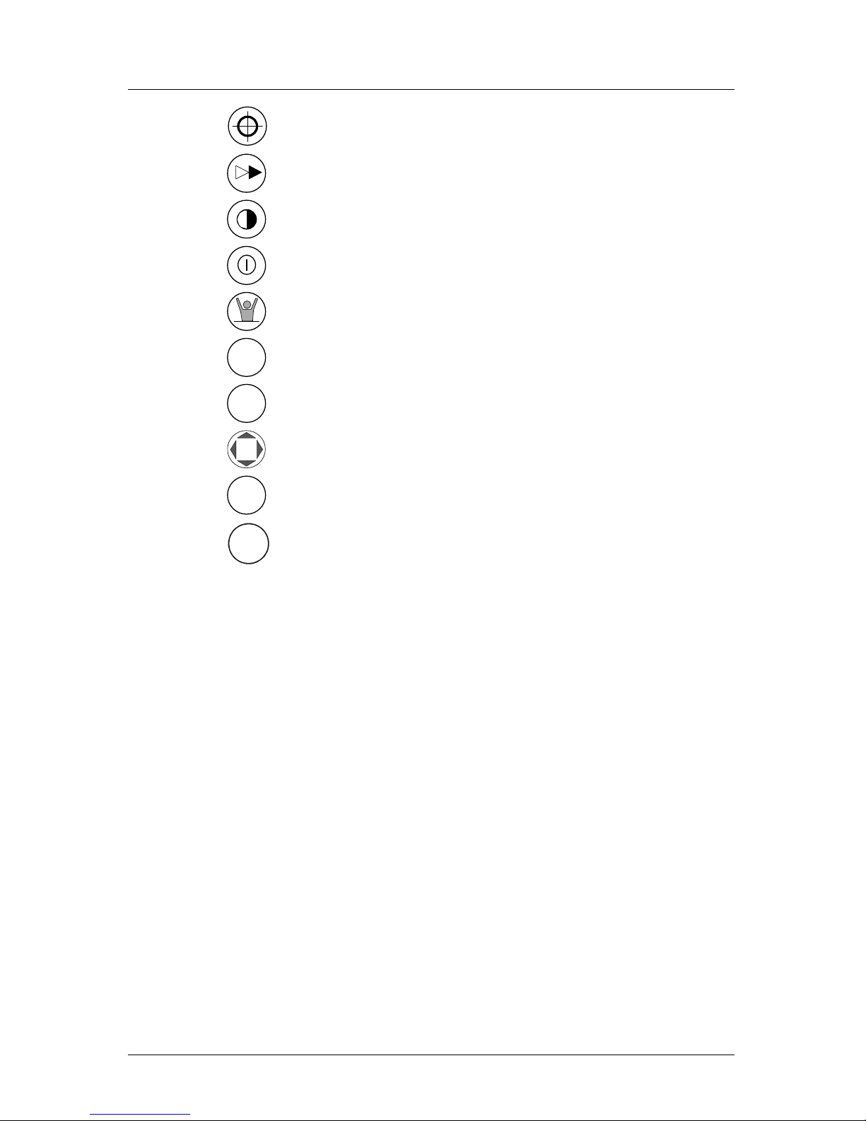
The Function Keys: ...................................................................... 11

ii Version 2.0
Operator Manual Table of Contents
Mark Position .............................................................. 11
GOTO .......................................................................... 12
LIGHT .......................................................................... 12
POWER ON/OFF ........................................................ 12
MAN OVER BOARD (MOB) ......................................... 13
E
E (EDIT) ...................................................................... 14
C
C (CLEAR) ................................................................... 14
CURSOR ..................................................................... 14
NAV
1
ABC FUNCTION .................................................................. 14
AIS
9
YZ
Automatic Identification System (AIS) ......................... 16
Navigate .................................................................................................... 17
Dead Reckoning ........................................................................... 18
NAV1 - The Panorama Screen ..................................................... 18
NAV2 - Basic Steering Information ............................................... 21
NAV 3 - Expanded Navigation Information .................................... 22
NAV4 - Sensor Input Navigation ................................................... 23
Route ........................................................................................................ 27
RTE1 - The Active Route ............................................................. 28
Creating a Route Using the GOTO Key: ................................. 29
Erasing an Existing Route ...................................................... 32
Creating a Multi-Waypoint Active Route ................................. 33
Insert By Number ................................................................... 34
Choose in Bank ..................................................................... 34
Insert New Waypoint .............................................................. 36
Insert Route ........................................................................... 37

Version 2.0 iii
Table of Contents Operator’s Manual
Maneuvering Within the Route ................................................ 38
Scrolling .......................................................................... 38
Skipping and Unpassing Waypoints ................................ 38
Inserting Waypoints or Routes into an Existing Route ..... 39
Reversing the Active Route ............................................. 41
ETA Setup ............................................................................. 43
SOG Based on Arrival Date & Time: ............................... 44
ETA Based on Speed: ..................................................... 44
RTE2 - The Route Bank ........................................................ 44
Waypoint ................................................................................................... 47
Creating and Editing Waypoints ............................................. 48
Waypoint Lock/Unlock .......................................................... 53
Removing Waypoints ............................................................. 55
Moving waypoints ................................................................... 57
Downloading Waypoints & Routes to Other Devices ............... 58
Rnn - Routes: .................................................................. 59
RTE - Active Route: ........................................................ 59
WPL - Waypoint Location - NMEA 0183 Standard: .......... 60
WPL - Waypoint with Symbols & Description - NMEA 0183
Expanded: ....................................................................... 61
Downloading Waypoints to a Personal Computer ................... 61
Uploading Waypoints from Other Devices .............................. 63
Uploading Waypoints from a Personal Computer ................... 64
Mark or Event.................................................................................. 66
GOTO ............................................................................................. 67
Plot ........................................................................................................... 70
PLOT 1 - Relative to Boat ............................................................ 72
Modifying the Active Route Using the Plot Screen.................. 72
Customizing the Display ........................................................ 74

iv Version 2.0
Operator Manual Table of Contents
PLOT 2 - Relative to Marker ......................................................... 77
PLOT3 ......................................................................................... 77
Plot Screen Use Examples .......................................................... 78
Station Keeping ..................................................................... 78
Grid Search ........................................................................... 79
Man Over Board ............................................................................... 80
Remote MOB ............................................................................... 81
Tide .......................................................................................................... 82
TIDE1 - Current Tide Display ........................................................ 82
TIDE2 - Tide Table Port List ......................................................... 83
Adding a Port ............................................................................... 85
Auxiliary .................................................................................................... 87
AUX1 - Alarm Log ...................................................................... 87
AUX2 - Speed Graph .................................................................... 88
AUX3 - Not Used ......................................................................... 88
AUX4 - Sun Almanac ................................................................... 88
AUX5 - Moon Phases ................................................................... 89
AUX6 - Batteries .......................................................................... 89
AUX7 -Unit Information ................................................................ 90
Position ..................................................................................................... 91
POS1 - Position Display (Large) ................................................... 91
Loran-C .................................................................................. 92
UTM ....................................................................................... 92
POS2 - Position, Altitude, Magnetic Variation, & Time ................. 93
POS3 - Position & Log ................................................................. 93
GPS .......................................................................................................... 95
GPS1 - GPS Status Screen ......................................................... 95
GPS6 - DGPS STATUS ............................................................... 96
GPS7 - DGPS Messages ............................................................. 98

Version 2.0 v
Table of Contents Operator’s Manual
Configuration ............................................................................................. 99
AIS Config .............................................................................99
AIS Static .................................................................................... 99
AIS Voyage .................................................................................. 99
Alarms ......................................................................................... 99
Anchor - Anchor Watch Alarm .................................................... 100
COG SOG - Course & Speed Filter Settings & Setup ................. 100
Compass - External Compass Input & Magnetic Variation Table 101
Datum - Current Position Calculation .......................................... 102
Depth - NMEA Input Control ....................................................... 103
DGPS - DGPS Configuration ...................................................... 104
DR - Dead Reckoning ................................................................. 106
Dual Contr. - Dual Station Control ............................................... 106
GPS - Elevation Mask Control .................................................... 107
Init Pos - Initial Position Entry .................................................... 107
Language - Language Configuration ............................................ 108
Lighting - Display/Keyboard Light & Contrast Control .................. 109
Log - Speed Log Input (Pulse or NMEA 0183) ............................ 109
Log Pulses - GPS SOG Log Pulse Output .................................. 111
MX480 - MX480 PC Chart Interface Control ................................. 111
Navigation - Navigation Method & Waypoint Pass Criterion Control
112
NMEA Out 1 through n* - NMEA 0183 Output Data Control ......... 115
Other Special Cases Affecting NMEA 0183 Records: .......... 120
Operation - General Setup and Control Settings ......................... 121
Organizer - Automated Message Reminders ............................... 122
Position - Positioning Reference, Mode, & Alarm Control ........... 123
Printout 2 - Printer Output Control .............................................. 125
ROT (Rate of Turn) ..................................................................... 128
Security ...................................................................................... 128
Serial I/O.................................................................................... 129

vi Version 2.0
Operator Manual Table of Contents
Time - Mode and Format Control ................................................ 129
Wind .......................................................................................... 130
Wpt & Rte Input - Uploading Waypoints into the Receiver .......... 131
Appendix A - Automatic Identification System (AIS) ................................ 133
Introduction ................................................................................ 133
AIS System Setup ..................................................................... 142
Configuring the AIS Static Setup ......................................... 142
Configuring the AIS Voyage ................................................. 147
AIS Function Key ....................................................................... 150
AIS 1 – OWN SHIP DATA ................................................... 150
AIS 2 - REMOTE SHIP LIST ............................................... 152
AIS 3 - RECEIVED (RX) SAFETY MESSAGES .................. 154
AIS 4 - TRANSMIT (TX) SAFETY MESSAGE ..................... 155
AIS 5 - TX SAFETY LIST .................................................... 157
AIS 6 - REGIONAL AREAS ................................................. 158
AIS 7- LONG RANGE (LR) DISPLAY ................................... 161
AIS 8 – AIS DATA LINK STATUS ........................................ 163
AIS 9 – AIS STATUS ........................................................... 164
AIS 10 - AIS PASSWORD .................................................. 165
PLOT 3 – AIS Plot Screen ......................................................... 167
Appendix B - Datum List ......................................................................... 168
Appendix C - Beacon List ........................................................................ 169
Appendix D- Engineering Mode ................................................................ 183
AUX7 - Unit Information & Self Test .......................................... 183
CDU Cold Start - Clearing Memory to Factory Default ................ 185
GPS - GPS CDU Troubleshooting ............................................. 186
GPS3 - Visible Satellite Information .................................... 186
GPS4 - GPS Position Uncertainty ........................................ 187
GPS5 - GPS Debug Screen ................................................ 187
MX421 Reset ............................................................................. 190
Appendix E - Dual Control Head Mode ..................................................... 191
Appendix F - Demonstration Mode ........................................................... 195
Glossary ................................................................................................. 197

Version 2.0 1
About GPS Navigation Operator’s Manual
About GPS Navigation
This GPS receiver is a precision navigation instrument utilizing the
latest technology available today to provide optimum performance
from the GPS satellite and Beacon land signals received. As with all
other forms of radio signals, the ultimate navigation result is depen-
dent upon the quality of these signals. Radio signals may, on occa-
sion, be distorted, jammed, or otherwise incorrect. As a result, your
position accuracy may occasionally be less than that which can nor-
mally be expected.
The Navstar Global Positioning System, commonly referred to as GPS,
is a satellite navigation system developed by the U.S. Department of
Defense to provide both military and civilian users with highly accu-
rate, worldwide, three dimensional navigation and time. By receiving
signals from orbiting GPS satellites, authorized users are able to con-
tinuously navigate with an accuracy on the order of 16 meters or bet-
ter, while civilian users are limited to accuracy’s of approximately 30
meters 2D RMS.
A technique referred to as Differential GPS (DGPS), allows users to
obtain maximum accuracy from the GPS system. DGPS requires the use
of two GPS receivers. One receiver, known as the Reference Station, is
placed at a surveyed location, the coordinates of which are precisely
known. The purpose of the differential GPS system is to use the refer-
ence station to measure the errors in the GPS signals and to compute
corrections to remove the errors. The corrections are then communi-
cated in real-time to the navigators, where they are combined with the
satellite signals received by the navigators, thereby improving their
navigation or positioning. The geographic validity of these correc-
tions decreases with distance from the reference station, but the cor-
rections are valid for navigators hundreds of kilometers from the refer-
ence station.
Marine radio beacons operating in the 283.5 to 325.0 KHz frequency
range are in widespread use for direction finding in coastal navigation.
Because the beacon system has been in place and widely used for
many years, it provides an effective means for the transmission of
DGPS signals. Depending on their local environment and power out-
put, their signals may be usable to several hundred miles. Marine bea-
cons provide an economical means of obtaining DGPS accuracy for
coastal navigators. GPS receivers with built-in beacon receivers are
designed to provide low cost reception of DGPS corrections broad-
cast (normally free of charge) by coastal authorities.
!

2Version 2.0
Operator’s Manual About GPS Navigation
Special Notes
GPS
Never rely solely on any single navigational aid.Always use whatever
information is available, and cross-check information when possible.
GPS expected position accuracy is better than 30 meters (95% of the
time) but may be up to 100 meters occasionally. The derived speed and
course readings may be hampered accordingly. The GPS system was
declared operational in 1994; however, the system’s availability and
accuracy are subject to change at the discretion of the US Department
of Defense.
DGPS
This GPS receiver’s position accuracy is improved to 5 meters or better
for 95% of the time, subject to the availability, accuracy, and control of
the DGPS correction transmission from the Beacon Station, or other
reference station connected at the time of usage.
The differential GPS position is that of the navigator GPS antenna, and
not that of the beacon antenna, if a separate beacon antenna is in use.
In addition, the beacon radio signal which carries the DGPS correc-
tions may be hampered by weather conditions such as heavy rain,
snow, and thunder storms. The beacon radio signal may also be inter-
rupted by powerful radio transmitters operating in long wavelength
bands.
Charts and Navigational Aids
Positions obtained from charts are not always as accurate as your
navigator (due to environmental changes, the dates of charts, and
datum offsets if the datum differs from the one in use by the naviga-
tor). The position of a floating aid can differ due to tide, set and drift.
!
!

Version 2.0 3
Functional Description Operator’s Manual
Functional Description
MX420 Configurations
The MX420 Navigation System is available in several configurations.
Please refer to the Auxiliary Unit Information section of the manual to
view sample screens to identify your particular model. Described be-
low are the various MX420 configurations and their differences.
MX420/2 GPS
This is a basic MX420 Control and Display Unit (CDU) model with two
(2) bidirectional user NMEA ports. This model is supplied with a MX421-
10 GPS only smart antenna. The smart antenna can achieve autono-
mous GPS accuracy better than 3 meters.
MX 422 Professional DGPS Navigat orM
X
422 Prof essional DGPS Navi
g
ator
Mx420 CDU
MX421-10 or MX521
Smart GPS Antenna
Basic MX420/2 and MX420/8 GPS & DGPS Configuration
MX420/2 DGPS
This is a basic MX420/2 CDU supplied with a combined GPS and
Beacon smart antenna (MX421B-10). The smart DGPS antenna unit
can achieve sub-meter accuracy in areas with good beacon differential
coverage.
MX420/8 GPS
This is an enhanced MX420 CDU equipped with eight (8) bidirectional
user NMEA ports. It is supplied with a GPS only smart antenna unit.
MX420/8 DGPS
This is a basic MX420/8 CDU supplied with a smart DGPS antenna
model MX421B-10 .

4Version 2.0
Operator’s Manual Functional Description
MX420/BR
This is a dual-head CDU system where a MX420/8 (operating as a
master) and a MX420/2 (operating as a slave) are supplied. A smart
DGPS antenna (MX421B-10) is supplied as a standard equipment. The
antenna unit is connected only to the MX420/8 master unit.
MX 4 22 Prof e ssional DGPS Navi gato r M
X
4 22 Prof e ssional DGPS Navig at or
MX420 CDU MX420 CDU
Master Unit Slave Unit
MX421B
Smart GPS
Antenna
MX420 BR Beacon and Remote Configuration
MX420/BRIM (Dual Control Integrity Monitor)
This is an enhanced Dual-Control configuration wherein two MX420/
8 CDUs and two MX421B-10 smart DGPS antennas are supplied. These
two MX420/8 units are connected in dual-control configuration but
they operate as independent navigator units with dedicated antennas.
The Integrity Monitor (IM) feature is a software option that works
only in the MX420/8 CDU hardware.
This configuration allows data to be shared between two remotely
separated stations (i.e. navigator’s station and helmsman’s station),
with independent access to various information fields. The purpose of
this configuration is to enable each CDU to calculate its own position,
then check the operational status of the other GPS receiver. The GPS
receiver with the best overall operational status then provides the
system position. This provides a fully redundant system, with self-
recovery capabilities. The Integrity Monitor function can be set to
Automatic switch over, forced to the Master unit, or forced to the
Slave unit for position and navigation functions.
MX 422 P rof essional DGPS Na vigat or M
X
422 Pr of essi on al DGPS Navigat or
MX420/8 CDU MX420/8 CDU
Unit 1 Unit 2
MX421B
Smart DGPS
Antenna
MX421B
Smart DGPS
Antenna
MX420/BRIM System Configuration

Version 2.0 5
DGPS Operator’s Manual
MX420/MKD (Minimum Keyboard and Display for AIS)
An entry level MX420/AIS CDU model supplied with an IMO-compli-
ant AIS transponder unit. All the AIS transponder setups and controls
are done through the MX420. It also gathers the ship’s sensor data
and organizes the information for transmission via AIS. High-speed
serial data ports are provided for output to the ECDIS chartplotter,
ARPA radar and other shipboard systems.
It also collects and decodes AIS reports from other stations and pro-
vides a readout from all AIS-equipped ships and shore stations. This
model does not have full navigation functions.
MX 422 Professional D GPS Navigator
MX420/AIS
GPS
Ant.
M423
A
IS Transponder
X
MX420/AIS Basic Configuration
MX420/AIS (AIS & Navigation System)
An enhanced MX420/MKD unit supplied with the Leica MX421B-10
smart DGPS antenna. This model has full navigation and AIS features.
MX420/AIS Navigation System Configuration
The Installation & Service Manual has more details on the parts
supplied with each configuration, and their associated part numbers.
Note:
1) In general, this manual will refer to all versions of this product line simply
as the MX420 CDU, MX420/AIS, CDU or navigator. Where distinction
between models is necessary, the particular model type will be indicated.

6Version 2.0
Operator’s Manual Keypad & Display Description
2) Three smart GPS/DGPS antenna models are compatible with the MX420
CDU. They are the MX421-10 (GPS or DGPS), MX525 (DGPS only) and
MX521(GPS or DGPS ).

Version 2.0 7
Keypad & Display Description Operator’s Manual
DGPS Beacon System
As Maritime Safety Administrations, Navy, and Coast Guard Organi-
zations realize the limitations of standard GPS positioning, many have
begun installing DGPS Beacon Stations. While an understanding of
this system is not necessary for operating receivers with internal bea-
con receivers, you may want to read on to have a better understanding
of how your receiver is capable of achieving the high levels of accu-
racy made possible by this network of transmitters.
The DGPS Beacon System is comprised of three segments: the refer-
ence station, Integrity Monitor (IM) equipment located at the beacon
site, and the Navigator equipment located on board the user’s boat or
vehicle. The DGPS beacon system design is illustrated below.
Navigator Site
N
A
V
PLOT
POS
E
TIDE
GP S
CF G
RTE
A
UX
DGPS
C
WP T
M
X
420 Navi
g
ationS
y
stem
Professional / Commercial
/
Personal Craft Users
Because of the limited range of the beacon transmitters, typically 150
to 400 km, the corrections generated by the reference station are al-
ways valid for users who can receive the correction signals and main-
tain a 5 meter or better accuracy figure.

8Version 2.0
Operator’s Manual Keypad & Display Description
Keypad & Display Description
NAV
PLOT
POS
E
TIDE
GPS
CFG
RTE
AUX
AIS
C
WPT
6289-01A.400
Traffic
Lights
Function KeysDisplay
Softkeys Cursor Key
Refer to the illustration above. The Traffic Lights on the left side of
the display will tell you how your navigator is operating.
Note: You need to take care in reading the traffic light indica-
tions, as there are overlapping possibilities between the
GPS and DGPS modes. If you are unsure of the current
operating mode, select the CFG function key and scroll
down to the DGPS selection. If the DGPS mode is se-
lected to anything other than Off, then follow the Differ-
ential GPS Traffic Light Operation. If the DGPS mode is
selected to Off, then follow the GPS Traffic Light Opera-
tion.

Version 2.0 9
Keypad & Display Description Operator’s Manual
Differential GPS Traffic Light Operation:
Red Flashing
Not tracking satellites (no position update). This is normal for the
first 2 minutes or so when turning the unit on. The very first time you
turn the unit on, or if the memory is reset or lost, this condition is also
normal. Allow the receiver to run for at least 30 minutes under these
circumstances. If it still does not change to Red Solid, refer to the
troubleshooting section of the Installation & Service Manual. An
icon similar to the one at left will be displayed in the upper left corner
of screen.
Red/Yellow Solid
Dead Reckoning . When normal GPS or DGPS operation is not avail-
able, this LED sequence is provided to quickly identify the DR naviga-
tion mode. A DR indicator is also displayed on all screens.
Red Solid
Tracking one or more satellites (no position update). This is also
normal for the first 2 minutes or so when turning the unit on. The very
first time you turn the unit on, allow the receiver to run for at least 20
minutes after changing to Red Solid to collect an almanac from the
satellites, regardless of whether a position update has been calculated
or not. This is also a normal indication if the HDOP is greater than 10,
if the receiver is tracking too few satellites, or for other reasons as well.
Read the GPS and DGPS function screens for more information.
Yellow/Green Solid
GPS position update; DGPS corrections are not being received. You
may see this from time to time during normal operation. It usually
occurs when the beacon signal is not available (either it is being blocked
by terrain or a local object or you are out of range of the transmitter)
and/or you are tracking 3, 4, or 5 satellites, and the satellites have poor
geometry relative to your position. The condition will normally go
back to green solid, when it picks up another beacon station. The
factory default level for dropping DGPS corrections is 60 seconds.
During this period, your positioning information is less than optimal,
and position accuracy may be off by as much as 3 to 5 meters. Press
the GPS function key and refer to the DGPS section in this manual for
guidance if this light condition occurs.
!
Other manuals for MX420
1
Table of contents
Other Leica Car Navigation System manuals