manuals.online logo
Brands
  1. Home
  2. •
  3. Brands
  4. •
  5. Leightronix
  6. •
  7. Server
  8. •
  9. Leightronix UltraNEXUS-SDI User guide

Leightronix UltraNEXUS-SDI User guide

PAG
E 1
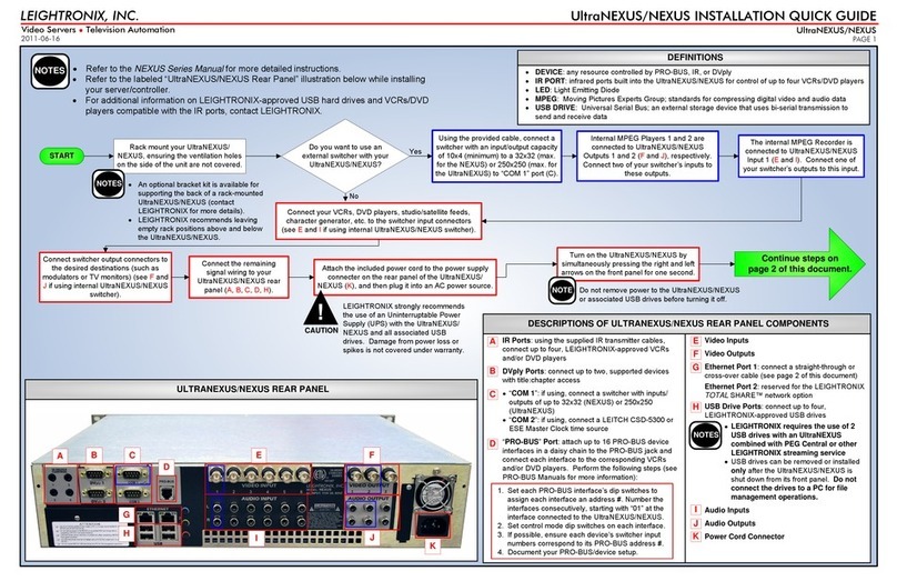
Refer to the labeled “UltraNEXUS-SDI Rear Panel” illustration below while installing your
server/controller.
For additional information on LEIGHTRONIX-approved USB hard drives and VCRs/DVD
players compatible with the IR ports, contact LEIGHTRONIX.
MPEG Player 1 Video Output
Broadcast Recorder Video Input
MPEG Player 2 Video Output
VOD Recorder Video Input
Ethernet Port 1: connect a straight-through or cross-over
cable (see page 4 of this document)
Ethernet Port 2: reserved for the LEIGHTRONIX TOTAL
SHARE™ network option
USB Drive Ports: connect up to four, LEIGHTRONIX-
approved USB drives
LEIGHTRONIX requires the use of 2 USB drives
when the UltraNEXUS-SDI is combined with a
LEIGHTRONIX streaming VOD service.
Remove/install USB drives only after shutting down
the UltraNEXUS-SDI its front panel. Do not connect
the drives to a PC for file management operations.
Power Cord Connector
NOTES
* IR Ports: using the supplied IR transmitter cables,
connect up to four, LEIGHTRONIX-approved VCRs and/
or DVD players
* DVply Ports: connect up to two, supported devices with
title:chapter access
* “COM 1”: connect a switcher with inputs/outputs of up
to 250x250
“COM 2”: if using, connect a LEITCH CSD-5300 or ESE
Master Clock time source
* “PRO-BUS”Port: attach up to 16 PRO-BUS device
interfaces in a daisy chain to the PRO-BUS jack and
connect each interface to the corresponding VCRs and/or
DVD players. Perform the following steps (see PRO-BUS
Manuals for more information):
ULTRANEXUS-SDI REAR PANEL CONNECTORS
1. Set each PRO-BUS interface’s dip switches to
assign each interface an address #. Number the
interfaces consecutively, starting with “01” at the
interface connected to the UltraNEXUS-SDI.
2. Set control mode dip switches on each interface.
3. If possible, ensure each device’s switcher input
numbers correspond to its PRO-BUS address #.
4. Document your PRO-BUS/device setup.
NOTES
LEIGHTRONIX, INC.
PAGE 1
UltraNEXUS-SDI INSTALLATION QUICK GUIDE
Video Servers ●Television Automation
ULTRANEXUS-SDI REAR PANEL
START
Rack mount your UltraNEXUS-
SDI, ensuring the ventilation
holes are not covered.
An optional bracket kit is available for supporting
the back of a rack-mounted UltraNEXUS-SDI
(contact LEIGHTRONIX for more details).
LEIGHTRONIX recommends leaving empty rack
positions above and below the UltraNEXUS-SDI.
NOTES
No: Continue steps on
page 2 of this document.
Are you using an external switcher
with your UltraNEXUS-SDI?
Yes: Continue steps on
page 3 of this document.
A
B
C
D
I
J
E
F
G
H
O
The UltraNEXUS-SDI supports embedded AES (SMPTE 272M) audio signals as well as non-embedded
AES (IEC 60958 type 1 balanced) and balanced, two-channel analog audio. To wire your system for non-
embedded audio, use the four audio terminal blocks on the rear panel, represented as follows:
MPEG Player 1 Audio Output VOD Recorder Audio Input
Broadcast Recorder Audio Input MPEG Player 2 Audio Output
Applicable to each terminal block, connect your non-embedded AES and analog audio signal wiring
according to the diagrams below.
AES3 Wiring Diagram 2-Channel Analog Wiring Diagram
ULTRANEXUS-SDI AUDIO INPUTS/OUTPUTS
K
L
M
N
* Only available for use when UltraNEXUS-SDI is connected to an external switcher.
2011-06-20
PAG
E 2
CONTINUE
Connect the video inputs on your
video source equipment to
UltraNEXUS-SDI MPEG player
video Outputs 1 (E) and 2 (G).
Will you be using one of the
LEIGHTRONIX streaming video-on-
demand (VOD) services with your
UltraNEXUS-SDI?
No
Yes
Connect a 1 input x 2 output
distribution amp between an output
on your video source equipment and
UltraNEXUS-SDI MPEG recorder
video Inputs 1 (F) and 2 (H).
Is your audio (SMPTE 272M)
embedded within the SD-SDI
digital video playback signal
(SMPTE 259M)?
No
Yes
Connect the corresponding audio
inputs on your video source equipment
to the analog or AES3 audio Outputs 1
(K) and 2 (N) on the UltraNEXUS-SDI
rear panel.
Connect the UltraNEXUS-SDI’s
MPEG broadcast recorder video
Input 1 (F) to one of your
source’s video equipment
outputs.
Will you be recording sources that do not
have embedded audio (SMPTE 272M) in
their video signals?
Yes
Connect a distribution amp between the
audio outputs on your video source
equipment and the analog or AES3
MPEG recorder audio Inputs 1 (L) and 2
(M) on the UltraNEXUS-SDI rear panel.
No
Will you be recording sources that do
not have embedded audio (SMPTE
272M) in their video signals?
Yes
Connect the audio outputs on
your video source equipment to
the analog or AES3 audio
broadcast Input 1 (L) and, if
using, VOD Input 2 (M) on the
UltraNEXUS-SDI rear panel.
No
If the 1x2 distribution amp splitting your
digital equipment’s video signal does not
support your audio signal, you may use a
separate audio distribution amp.
NOTES
Connect your USB hard drive(s) to
the UltraNEXUS-SDI rear panel (J).
Attach the included power cord to the power supply
connector on the rear panel of the UltraNEXUS-SDI
(O), and then plug it into an AC power source.
Turn on the UltraNEXUS-SDI by
simultaneously pressing the right and left
arrows on the front panel for one second.
LEIGHTRONIX strongly recommends the
use of an Uninterruptable Power Supply
(UPS) with the UltraNEXUS-SDI and all
associated USB drives. Damage from power
loss or spikes is not covered under warranty.
Do not remove power to the UltraNEXUS-SDI or
associated USB drives before turning it off.
NOTE
If using, connect a LEITCH CSD-
5300 or ESE Master Clock time
source to the “COM 2” port (C) on
the UltraNEXUS-SDI rear panel.
CAUTION
PAGE 2
UltraNEXUS-SDI INSTALLATION QUICK GUIDE
2011-06-20
LEIGHTRONIX, INC.
Video Servers ●Television Automation
ULTRANEXUS-SDI CONFIGURATION WITHOUT AN EXTERNAL SWITCHER
Continue steps on
page 4 of this document.
PAG
E 3
CONTINUE
Connect your switcher (4x4
minimum, 250x250 maximum)
to the “COM 1” port (C) on the
UltraNEXUS-SDI rear panel.
Will you be using one of the
LEIGHTRONIX streaming video-on-
demand (VOD) services with your
UltraNEXUS-SDI?
No
Yes Yes
No
No
Yes
Yes
No
Yes
No
Connect your video source
equipment (VCRs, DVD players,
studio/satellite feeds, character
generator, etc.) to your external
switcher’s input connectors.
Connect your switcher’s output
connectors to the your
destinations (such as
modulators or TV monitors).
Connect the device control wiring
between your UltraNEXUS-SDI
rear panel ports and
corresponding video sources, as
applicable (A,B,D).
Is your audio (SMPTE 272M)
embedded within the SD-SDI
digital video playback signal
(SMPTE 259M)?
Connect the audio outputs on your
switcher to the analog or AES3 audio
Outputs 1 (K) and 2 (N) on the
UltraNEXUS-SDI rear panel.
Connect a 1 input x 2 output
distribution amp between an
output on your switcher and
UltraNEXUS-SDI MPEG recorder
video Inputs 1 (F) and 2 (H).
Connect your switcher video
inputs to UltraNEXUS-SDI
MPEG player video Ouputs 1
(E) and 2 (G).
Will you be recording sources that do
not have embedded audio (SMPTE
272M) in their video signals?
Connect a distribution amp between
the audio outputs on your switcher
and the analog or AES3 audio MPEG
recorder Inputs 1 (L) and 2 (M) on the
UltraNEXUS-SDI rear panel.
If the 1x2 distribution amp splitting
your digital equipment’s video
signal does not support your audio
signal, you may use a separate
audio distribution amp.
NOTES
Connect the UltraNEXUS-SDI’s
MPEG broadcast recorder
video Input 1 (F) and VOD
recorder video Input 2 (H) to
separate switcher outputs.
Will you be recording
sources that do not have
embedded audio (SMPTE
272M) in their video
signals?
The UltraNEXUS-SDI is compatible with any all-digital
models (SDI video/AES audio) from the LEIGHTRONIX-
supported external routing switcher series listed in the
NEXUS Series Manual. Contact the manufacturers for
help in selecting specific models.
NOTE
Connect your USB hard drive(s) to
the UltraNEXUS-SDI rear panel (J).
Attach the included power cord to the power supply
connector on the rear panel of the UltraNEXUS-SDI
(O), and then plug it into an AC power source.
Turn on the UltraNEXUS-SDI by
simultaneously pressing the right and left
arrows on the front panel for one second.
LEIGHTRONIX strongly recommends the use of an
Uninterruptable Power Supply (UPS) with the
UltraNEXUS-SDI and all associated USB drives.
Damage from power loss or spikes is not covered
under warranty.
Do not remove power to the UltraNEXUS-SDI or
associated USB drives before turning it off.
NOTE
If using, connect a LEITCH CSD-
5300 or ESE Master Clock time
source to the “COM 2” port (C) on
the UltraNEXUS-SDI rear panel.
CAUTION
2011-06-20
LEIGHTRONIX, INC.
PAGE 3
UltraNEXUS-SDI INSTALLATION QUICK GUIDE
Video Servers ●Television Automation
ULTRANEXUS-SDI CONFIGURATION WITH AN EXTERNAL SWITCHER
Do you want the broadcast and
VOD recorders to automatically
record the same content?
Connect the UltraNEXUS-SDI’s
MPEG broadcast recorder video
Input 1 (F) to one of your
source’s video equipment
outputs.
Connect the audio outputs on your video
equipment to the analog or AES3 audio
broadcast Input 1 (L) and, if using, VOD Input
2 (M) on the UltraNEXUS-SDI rear panel.
Continue steps on
page 4 of this document.
PAG
E 4
To access a remote UltraNEXUS-SDI through the Internet, contact your
ISP service provider and network administrator for more information.
ENTERING TCP/IP ADDRESSES INTO ULTRANEXUS-SDI FRONT PANEL
2. Enter each address into its corresponding entry screen:
IP address: “Edit unit IP Address” screen
Subnet mask address: “Edit unit Subnet Mask” screen
Gateway address: “Edit unit Gateway Addr” screen
3. The UltraNEXUS-SDI must be powered down and then powered back up to apply any address changes
(simultaneously press and for one second to turn off and repeat to turn back on).
1. Enter front panel password according to the following steps:
a. Press the key to display the password entry screen.
b. Press the key 5 times to enter the factory-default password and display the “CONFIG MENU” screen.
NOTE
`
TCP/IP Network
Scheduling &
Management
Software
10/100/1000 Ethernet
January 1, 2005
12:00:00 PM
Schedule Files
System Status & Log Files
NETWORK ETHERNET CONNECTION
Connect UltraNEXUS-SDI to an existing Ethernet TCP/IP Network per the following
steps:
1. Obtain the following from your technical support personnel or network administrator and enter into the front
panel of your UltraNEXUS-SDI (refer to “Entering TCP/IP Addresses into UltraNEXUS-SDI Front Panel”
below):
IP address
Subnet mask
Gateway address
2. Using a straight-through RJ-45 Ethernet cable, connect the UltraNEXUS-SDI’s Ethernet Port 1 (I) to a 10/100/
1000 BASE-T hub or switch on the TCP/IP network.
3. Ensure the UltraNEXUS-SDI and PC have been properly configured for Ethernet network access by checking
to see that the yellow LED above the Ethernet port is on. If the yellow LED does not turn on, check the
following:
Proper addresses have been entered into the UltraNEXUS-SDI front panel
Straight-through cable was used to attach UltraNEXUS-SDI to the network
`
Scheduling &
Management
Software
10/100/1000 Ethernet
January 1, 2005
12:00:00 PM
Schedule Files
System Status & Log Files
DIRECT ETHERNET CONNECTION
Connect UltraNEXUS-SDI directly to a PC per the following steps:
1. If necessary, install and configure a 10/100/1000 BASE-T Ethernet Network Interface Card (NIC) on the PC.
Refer to the NIC documentation and technical support for further instructions.
2. PC NETWORKING ADDRESSES: obtain your PC’s TCP/IP networking IP address and subnet mask from
Windows (see your computer manual for more detailed instructions).
3. UltraNEXUS-SDI NETWORKING ADDRESSES: Enter the following IP and subnet mask addresses into the
front panel of your UltraNEXUS-SDI (refer to “Entering TCP/IP Addresses into UltraNEXUS-SDI Front Panel” at
right):
IP address: one number above your PC’s IP address (for ex., if your PC’s IP address is 10.255.9.15, set
your Controller to 10.255.9.16)
Subnet mask: your PC’s subnet mask address
4. Using a cross-over RJ-45 Ethernet cable, connect the UltraNEXUS-SDI Ethernet Port 1 (I) to the PC’s NIC.
5. Ensure the UltraNEXUS-SDI and PC have been properly configured for Ethernet network access by checking to
see that the yellow LED above the Ethernet port is on. If the yellow LED does not turn on, check the following:
Proper addresses have been entered into the UltraNEXUS-SDI front panel
Crossover cable was used to attach UltraNEXUS-SDI to PC
Configure your UltraNEXUS-SDI for Ethernet network
access. Two of the most common Ethernet
connection scenarios are described on this page.
CONTINUE END
2011-06-20
LEIGHTRONIX, INC.
PAGE 4
UltraNEXUS-SDI INSTALLATION QUICK GUIDE
Video Servers ●Television Automation

Other Leightronix Server manuals

Leightronix UltraNEXUS HD Blade User manual

Leightronix

Leightronix UltraNEXUS HD Blade User manual

Leightronix MINI-T-NX User manual

Leightronix

Leightronix MINI-T-NX User manual

Leightronix UltraNEXUS User guide

Leightronix

Leightronix UltraNEXUS User guide

Leightronix UltraNEXUS-HD Flex User manual

Leightronix

Leightronix UltraNEXUS-HD Flex User manual

Leightronix UltraNEXUS User manual

Leightronix

Leightronix UltraNEXUS User manual

Leightronix UltraNEXUS-HD X5 User manual

Leightronix

Leightronix UltraNEXUS-HD X5 User manual

Leightronix UltraNEXUS-HD Cast User manual

Leightronix

Leightronix UltraNEXUS-HD Cast User manual

Leightronix UltraNEXUS-HD X2 User manual

Leightronix

Leightronix UltraNEXUS-HD X2 User manual

Popular Server manuals by other brands

TimeLink TMS2000 user manual

TimeLink

TimeLink TMS2000 user manual

Acer Altos G530 Series Quick start user guide

Acer

Acer Altos G530 Series Quick start user guide

Lenovo ThinkServer TD100 Hardware Maintenance Manual

Lenovo

Lenovo ThinkServer TD100 Hardware Maintenance Manual

IBM 8832 Deployment guide

IBM

IBM 8832 Deployment guide

Korenix JetPort 5201 Quick installation guide

Korenix

Korenix JetPort 5201 Quick installation guide

Intergraph InterServe 800 SL System setup

Intergraph

Intergraph InterServe 800 SL System setup

Home Automation CAMERA SERVER 87A00-1 Installation and user guide

Home Automation

Home Automation CAMERA SERVER 87A00-1 Installation and user guide

Sun Oracle 4540 - Phaser Copystation Service manual

Sun Oracle

Sun Oracle 4540 - Phaser Copystation Service manual

Gateway 9415 user guide

Gateway

Gateway 9415 user guide

HP ProLiant DL380 G3 with MSA1000 Setup and installation guide

HP

HP ProLiant DL380 G3 with MSA1000 Setup and installation guide

Hivron QTP40 product manual

Hivron

Hivron QTP40 product manual

Dell PowerEdge EMT Getting started guide

Dell

Dell PowerEdge EMT Getting started guide

NEC EXPRESS5800/120Re-2 Service guide

NEC

NEC EXPRESS5800/120Re-2 Service guide

Nortel Meridian 1 Description, installation, and maintenance

Nortel

Nortel Meridian 1 Description, installation, and maintenance

Lantronix UDS1100 user guide

Lantronix

Lantronix UDS1100 user guide

IBM 7945B2U Brochure & specs

IBM

IBM 7945B2U Brochure & specs

MANNL ELEKTRONIK Connect 410S manual

MANNL ELEKTRONIK

MANNL ELEKTRONIK Connect 410S manual

Dell 8 Installation

Dell

Dell 8 Installation

manuals.online logo
manuals.online logoBrands
  • About & Mission
  • Contact us
  • Privacy Policy
  • Terms and Conditions

Copyright 2025 Manuals.Online. All Rights Reserved.