manuals.online logo
Brands
  1. Home
  2. •
  3. Brands
  4. •
  5. Leightronix
  6. •
  7. Server
  8. •
  9. Leightronix UltraNEXUS User guide

Leightronix UltraNEXUS User guide

PAG
E 1
Connect the remaining
signal wiring to your
UltraNEXUS/NEXUS rear
panel (A, B, C, D, H).
START Do you want to use an
external switcher with your
UltraNEXUS/NEXUS?
Rack mount your UltraNEXUS/
NEXUS, ensuring the ventilation holes
on the side of the unit are not covered.
Connect your VCRs, DVD players, studio/satellite feeds,
character generator, etc. to the switcher input connectors
(see Eand I if using internal UltraNEXUS/NEXUS switcher).
Connect switcher output connectors to
the desired destinations (such as
modulators or TV monitors) (see Fand
Jif using internal UltraNEXUS/NEXUS
switcher).
Attach the included power cord to the power supply
connecter on the rear panel of the UltraNEXUS/
NEXUS (K), and then plug it into an AC power source.
Turn on the UltraNEXUS/NEXUS by
simultaneously pressing the right and left
arrows on the front panel for one second.
LEIGHTRONIX strongly recommends
the use of an Uninterruptable Power
Supply (UPS) with the UltraNEXUS/
NEXUS and all associated USB
drives. Damage from power loss or
spikes is not covered under warranty.
An optional bracket kit is available for
supporting the back of a rack-mounted
UltraNEXUS/NEXUS (contact
LEIGHTRONIX for more details).
LEIGHTRONIX recommends leaving
empty rack positions above and below
the UltraNEXUS/NEXUS.
Yes
Refer to the NEXUS Series Manual for more detailed instructions.
Refer to the labeled “UltraNEXUS/NEXUS Rear Panel” illustration below while installing
your server/controller.
For additional information on LEIGHTRONIX-approved USB hard drives and VCRs/DVD
players compatible with the IR ports, contact LEIGHTRONIX.
NOTES
No
Continue steps on
page 2 of this document.
ULTRANEXUS/NEXUS REAR PANEL
Video Inputs
Video Outputs
Ethernet Port 1: connect a straight-through or
cross-over cable (see page 2 of this document)
Ethernet Port 2: reserved for the LEIGHTRONIX
TOTAL SHARE™ network option
USB Drive Ports: connect up to four,
LEIGHTRONIX-approved USB drives
LEIGHTRONIX requires the use of 2
USB drives with an UltraNEXUS
combined with PEG Central or other
LEIGHTRONIX streaming service
USB drives can be removed or installed
only after the UltraNEXUS/NEXUS is
shut down from its front panel. Do not
connect the drives to a PC for file
management operations.
Audio Inputs
Audio Outputs
Power Cord Connector
E
F
G
H
I
J
K
NOTES
IR Ports: using the supplied IR transmitter cables,
connect up to four, LEIGHTRONIX-approved VCRs
and/or DVD players
DVply Ports: connect up to two, supported devices
with title:chapter access
“COM 1”: if using, connect a switcher with inputs/
outputs of up to 32x32 (NEXUS) or 250x250
(UltraNEXUS)
“COM 2”: if using, connect a LEITCH CSD-5300 or
ESE Master Clock time source
“PRO-BUS”Port: attach up to 16 PRO-BUS device
interfaces in a daisy chain to the PRO-BUS jack and
connect each interface to the corresponding VCRs
and/or DVD players. Perform the following steps (see
PRO-BUS Manuals for more information):
A
B
C
D
DESCRIPTIONS OF ULTRANEXUS/NEXUS REAR PANEL COMPONENTS
ABCDE F
G
HIJK
Do not remove power to the UltraNEXUS/NEXUS
or associated USB drives before turning it off.
1. Set each PRO-BUS interface’s dip switches to
assign each interface an address #. Number the
interfaces consecutively, starting with “01” at the
interface connected to the UltraNEXUS/NEXUS.
2. Set control mode dip switches on each interface.
3. If possible, ensure each device’s switcher input
numbers correspond to its PRO-BUS address #.
4. Document your PRO-BUS/device setup.
CAUTION
NOTE
NOTES DEVICE: any resource controlled by PRO-BUS, IR, or DVply
IR PORT: infrared ports built into the UltraNEXUS/NEXUS for control of up to four VCRs/DVD players
LED: Light Emitting Diode
MPEG: Moving Pictures Experts Group; standards for compressing digital video and audio data
USB DRIVE: Universal Serial Bus; an external storage device that uses bi-serial transmission to
send and receive data
DEFINITIONS
2011-06-16
LEIGHTRONIX, INC.
PAGE 1
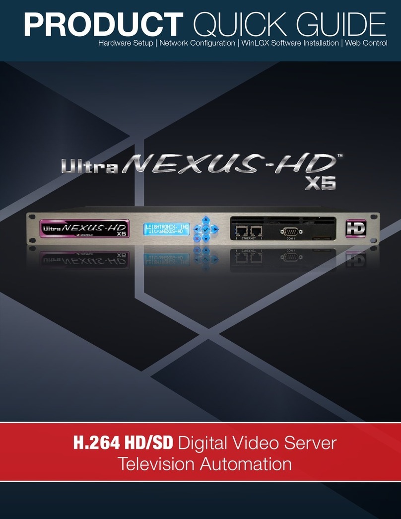
UltraNEXUS/NEXUS INSTALLATION QUICK GUIDE
UltraNEXUS/NEXUS
Using the provided cable, connect a
switcher with an input/output capacity
of 10x4 (minimum) to a 32x32 (max.
for the NEXUS) or 250x250 (max. for
the UltraNEXUS) to “COM 1” port (C).
The internal MPEG Recorder is
connected to UltraNEXUS/NEXUS
Input 1 (Eand I). Connect one of
your switcher’s outputs to this input.
Internal MPEG Players 1 and 2 are
connected to UltraNEXUS/NEXUS
Outputs 1 and 2 (Fand J), respectively.
Connect two of your switcher’s inputs to
these outputs.
Video Servers ●Television Automation
PAG
E 2
To access a remote UltraNEXUS/NEXUS through the Internet, contact
your ISP service provider and network administrator for more information.
ENTERING TCP/IP ADDRESSES INTO ULTRANEXUS/NEXUS FRONT PANEL
2. Enter each address into its corresponding entry screen:
IP address: “Edit unit IP Address” screen
Subnet mask address: “Edit unit Subnet Mask” screen
Gateway address: “Edit unit Gateway Addr” screen
3. The UltraNEXUS/NEXUS must be powered down and then powered back up to apply any address changes
(simultaneously press and for one second to turn off and repeat to turn back on).
1. Enter front panel password according to the following steps:
a. Press the key to display the password entry screen.
b. Press the key 5 times to enter the factory-default password and display the “CONFIG MENU” screen.
NOTE
`
TCP/IP Network
Scheduling &
Management
Software
10/100/1000 Ethernet
January 1, 2005
12:00:00 PM
Schedule Files
System Status & Log Files
NETWORK ETHERNET CONNECTION
Connect UltraNEXUS/NEXUS to an existing Ethernet TCP/IP Network per the following
steps:
1. Obtain the following from your technical support personnel or network administrator and enter into the front
panel of your UltraNEXUS/NEXUS (refer to “Entering TCP/IP Addresses into UltraNEXUS/NEXUS Front
Panel” below):
IP address
Subnet mask
Gateway address
2. Using a straight-through RJ-45 Ethernet cable, connect the UltraNEXUS/NEXUS’s Ethernet Port 1 (G) to a
10/100/1000 BASE-T hub or switch on the TCP/IP network.
3. Ensure the UltraNEXUS/NEXUS and PC have been properly configured for Ethernet network access by
checking to see that the yellow LED above the Ethernet port is on. If the yellow LED does not turn on, check
the following:
Proper addresses have been entered into the UltraNEXUS/NEXUS front panel
Straight-through cable was used to attach UltraNEXUS/NEXUS to the network
`
Scheduling &
Management
Software
10/100/1000 Ethernet
January 1, 2005
12:00:00 PM
Schedule Files
System Status & Log Files
DIRECT ETHERNET CONNECTION
Connect UltraNEXUS/NEXUS directly to a PC per the following steps:
1. If necessary, install and configure a 10/100/1000 BASE-T Ethernet Network Interface Card (NIC) on the PC.
Refer to the NIC documentation and technical support for further instructions.
2. PC NETWORKING ADDRESSES: obtain your PC’s TCP/IP networking IP address and subnet mask from
Windows (see the UltraNEXUS/NEXUS Manual or your computer manual for more detailed instructions).
3. UltraNEXUS/NEXUS NETWORKING ADDRESSES: Enter the following IP and subnet mask addresses into the
front panel of your UltraNEXUS/NEXUS (refer to “Entering TCP/IP Addresses into UltraNEXUS/NEXUS Front
Panel” at right):
IP address: one number above your PC’s IP address (for ex., if your PC’s IP address is 10.255.9.15, set
your Controller to 10.255.9.16)
Subnet mask: your PC’s subnet mask address
4. Using a cross-over RJ-45 Ethernet cable, connect the UltraNEXUS/NEXUS Ethernet Port 1 (G) to the PC’s NIC.
5. Ensure the UltraNEXUS/NEXUS and PC have been properly configured for Ethernet network access by
checking to see that the yellow LED above the Ethernet port is on. If the yellow LED does not turn on, check
the following:
Proper addresses have been entered into the UltraNEXUS/NEXUS front panel
Crossover cable was used to attach UltraNEXUS/NEXUS to PC
PAGE 2
UltraNEXUS/NEXUS INSTALLATION QUICK GUIDE
UltraNEXUS/NEXUS 2011-06-16
LEIGHTRONIX, INC.
Configure UltraNEXUS/NEXUS for Ethernet network
access. Two of the most common Ethernet
connection scenarios are described on this page.
CONTINUE END
Video Servers ●Television Automation
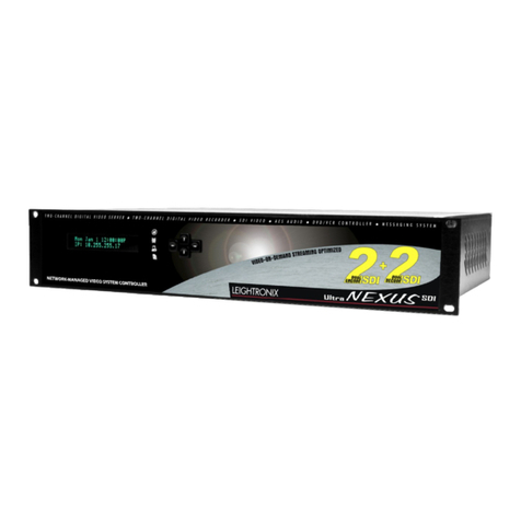
Other manuals for UltraNEXUS

1

This manual suits for next models

1

Other Leightronix Server manuals

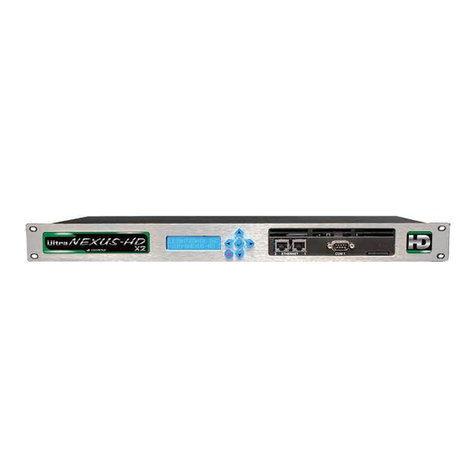
Leightronix UltraNEXUS-HD Cast User manual

Leightronix

Leightronix UltraNEXUS-HD Cast User manual

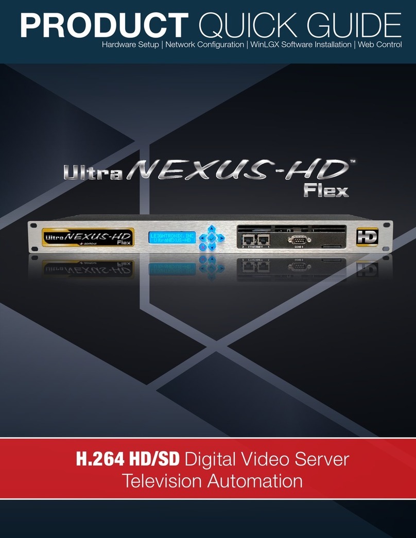
Leightronix UltraNEXUS-HD Flex User manual

Leightronix

Leightronix UltraNEXUS-HD Flex User manual

Leightronix UltraNEXUS HD Blade User manual

Leightronix

Leightronix UltraNEXUS HD Blade User manual

Leightronix UltraNEXUS-HD X2 User manual

Leightronix

Leightronix UltraNEXUS-HD X2 User manual

Leightronix UltraNEXUS-SDI User guide

Leightronix

Leightronix UltraNEXUS-SDI User guide

Leightronix UltraNEXUS-HD X5 User manual

Leightronix

Leightronix UltraNEXUS-HD X5 User manual

Leightronix MINI-T-NX User manual

Leightronix

Leightronix MINI-T-NX User manual

Leightronix UltraNEXUS User manual

Leightronix

Leightronix UltraNEXUS User manual

Popular Server manuals by other brands

IBM Power System System E950 manual

IBM

IBM Power System System E950 manual

HPE PoLiant DL180 Gen10 Short Depth Product End-of-Life Disassembly Instructions

HPE

HPE PoLiant DL180 Gen10 Short Depth Product End-of-Life Disassembly Instructions

Axis 2411 Administration manual

Axis

Axis 2411 Administration manual

Supermicro SuperServer 6011D Hardware install guide

Supermicro

Supermicro SuperServer 6011D Hardware install guide

Harmonic Spectrum MediaDeck 7000 installation guide

Harmonic

Harmonic Spectrum MediaDeck 7000 installation guide

HP ProLiant XL230a Gen9 Maintenance and service guide

HP

HP ProLiant XL230a Gen9 Maintenance and service guide

Pepperl+Fuchs BTC01 manual

Pepperl+Fuchs

Pepperl+Fuchs BTC01 manual

HP HPE SimpliVity 380 Gen10 Installation and maintenance guide

HP

HP HPE SimpliVity 380 Gen10 Installation and maintenance guide

Western Digital Sentinel DS5100 Administrator and maintenance guide

Western Digital

Western Digital Sentinel DS5100 Administrator and maintenance guide

Sun Microsystems Sun Fire V890 Product notes

Sun Microsystems

Sun Microsystems Sun Fire V890 Product notes

Lenovo ThinkServer TS200v nformasjon om garanti og støtte

Lenovo

Lenovo ThinkServer TS200v nformasjon om garanti og støtte

Fujitsu PRIMERGY RX900 S2 Upgrade and maintenance manual

Fujitsu

Fujitsu PRIMERGY RX900 S2 Upgrade and maintenance manual

NETGEAR ReadyNAS 3100 Hardware manual

NETGEAR

NETGEAR ReadyNAS 3100 Hardware manual

RuggedCom RuggedWireless RS920W Specifications

RuggedCom

RuggedCom RuggedWireless RS920W Specifications

IBM 88861TU Installation and user guide

IBM

IBM 88861TU Installation and user guide

HP ProLiant ML110 Operation and maintenance guide

HP

HP ProLiant ML110 Operation and maintenance guide

SNAP 410 quick start guide

SNAP

SNAP 410 quick start guide

IBM 8668 - Eserver xSeries 232 Hardware Maintenance Manual

IBM

IBM 8668 - Eserver xSeries 232 Hardware Maintenance Manual

manuals.online logo
manuals.online logoBrands
  • About & Mission
  • Contact us
  • Privacy Policy
  • Terms and Conditions

Copyright 2025 Manuals.Online. All Rights Reserved.